With the development of advanced manufacturing technologies, the importance of functionally graded materials is growing as they are advantageous over widely used traditional composites. In this paper, we present a novel peridynamic model for higher order functional graded plates for various thicknesses. Moreover, the formulation eliminates the usage of shear correction factors. Euler–Lagrange equations and Taylor’s expansion are utilised to derive the governing equations. The capability of the developed peridynamic model is demonstrated by considering several benchmark problems. In these benchmark cases simply supported, clamped and mixed boundary conditions are also tested. The peridynamic results are also verified by their finite element analysis counterparts. According to the comparison, peridynamic and finite element analysis results agree very well with each other.
Utilisation of functionally graded materials (FGMs) is increasing due to the advancement in manufacturing technologies and their advantages with respect to fibre-reinforced composites. As the properties of FGMs vary continuously along the material, the structure does not suffer from the discontinuity problem, as can be seen in fibre-reinforced composite materials, which can lead to the delamination problem. In the literature, there have been several studies related to the analysis of plates made of FGMs. Among these, Qian and Batra [1] performed thermoelastic analysis of thick plates made of FGMs. Their approach is based on the meshless Petrov–Galerkin method and higher order shear and normal deformable plate theory. Ferreira et al. [2] utilised a meshless method to determine static deformations of simply supported plates made of FGMs based on a third-order shear deformation theory. Cheng and Batra [3] used first-order and third-order shear deformation theories to examine plates made of FGMs. Batra [4] used the principle of virtual work and higher-order shear and normal deformable theory to examine functionally graded incompressible linear elastic plates. Belabed et al. [5] introduced a higher-order shear and normal deformation theory for functionally graded plates by considering hyperbolic variation of displacements along the thickness. Their formulation did not require the usage of shear correction factors. Xiang and Kang [6] examined the bending behaviour of plates made of FGMs. They introduced an nth-order shear deformation theory by using a meshless method based on a global collocation technique. Zhang et al. [7] introduced a semi-analytical approach to analyse in-plane deformation of functionally graded plates. Their methodology is based on scaled boundary finite element formulation.
In this paper, a novel higher-order plate (HOP) formulation for FGMs is developed by using an alternative formulation, peridynamics. A shear correction factor is not required for the current formulation. On the other hand, the developed peridynamic formulation is suitable for plates with various thicknesses, and does not require a shear correction factor. Silling [8] introduced the peridynamics method to overcome the problem of having discontinuities in the classical continuum mechanics formulation. This way, if cracks exist in the structure, the peridynamics formulation becomes suitable. Moreover, due to its length-scale parameter, horizon (interaction domain), it is possible to represent non-local deformation behaviour. Peridynamics has been used to investigate many different materials ranging from metals [9,10], composite materials [11–16], ceramics [17–19], concrete [20–23] and functionally graded materials [25–27]. Peridynamics is also suitable to perform multiphysics analysis [28,29]. Several beam [30–33] and plate formulations [34–37] are also available in the peridynamic framework. A review of benchmark experiments for the validation of peridynamic models is given in Diehl et al. [38]. However, higher-order plate formulation in peridynamic formulation for functionally graded materials is currently not available in the literature; this is the key motivation of this study. In this concept, Euler–Lagrange equation and Taylor’s expansion are utilised to derive the equations of motion. To validate the developed methodology, several benchmark problems are considered. The peridynamic predictions are compared with finite element analysis (FEA) solutions.
2. Classical HOP formulation for FGMs
According to HOP formulation, the displacements of a material particle can be represented as a function of material particles located on the mid-plane of the plate. If the mid-plane is located on plane, the displacements can be represented by using Taylor’s expansion as
where z represents the transverse coordinate along the thickness direction. Ignoring higher-order terms, the expressions given in equations (1a) to (1c) can be rewritten as
where and denote the membrane displacements, denotes the transverse displacement of mid-plane, respectively, and , , , , , , and are arisen out of the Taylor expansion and introduced as eight additional independent variables. The parameter represents the rotation of mid-plane about -axis. On the other hand, the parameter represents the rotation of mid-plane about negative -axis.
Next, the strain components can be obtained by using equations (2a) to (2c) as
The strain-displacement relationships given in equations (3a) to (3f) can be written by using indicial notation as
where the lower case parameters and range from 1 to 3 and upper case parameters and range from 1 to 2.
Assuming the material is planar isotropic and obeying the 3D constitutive relation, the stress components can be given by
where is the elastic modulus tensor which can be described as
where represents the shear modulus and represents the Poisson’s ratio. These parameters are considered to vary through the thickness: and .
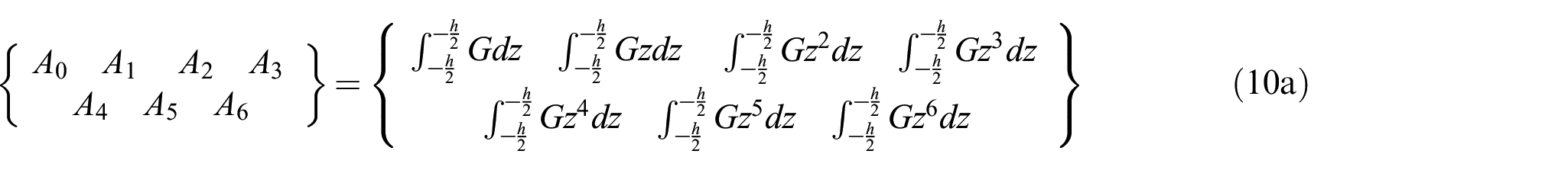
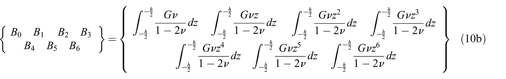
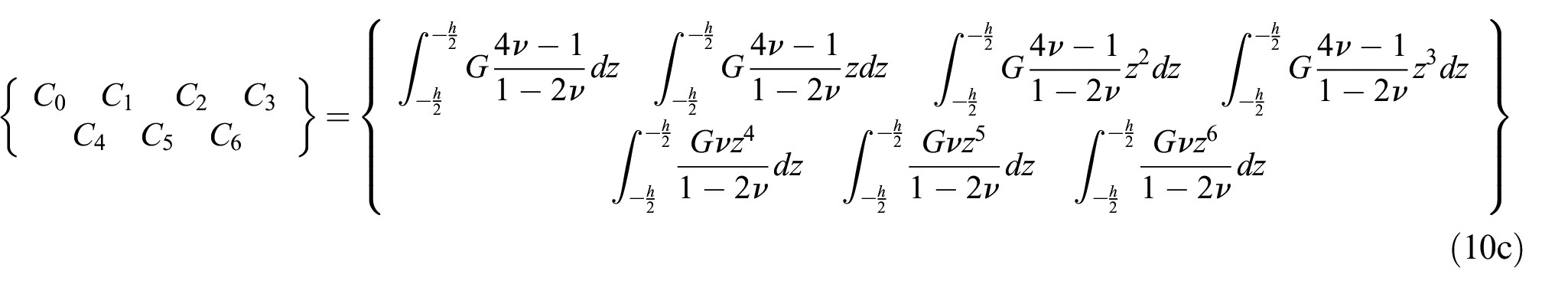
where the material property coefficients , can are given as
3. Peridynamic HOP Formulation for FGMs
Peridynamics is a new continuum mechanics formulation which was introduced by Silling [8] to overcome the limitations of classical continuum mechanics. Peridynamic equations of motion are in integro-differential equation form instead of the partial differential equations used in classical continuum mechanics. According to peridynamics, each material point is not only interacting with the material points located in its immediate vicinity, but is also interacting with other material points in a non-local manner located within a region of finite radius named as ‘horizon’, . The original peridynamic equations of motion for a material point located at can be written as [8]
where is the location of the material point at which the material point located at is interacting, is the peridynamic force between the material points located at and , is the acceleration of the material point located at , and are the displacements of the material points located at and , respectively, is the body force of the material point located at , is the incremental volume of the material point located at , is the density and is time. The analytical solution of equation (11) is usually not possible. Instead, numerical approaches, especially the meshless method, are widely utilised. Therefore, equation (11) can be written in a discretised form for a particular material point k as
where is the peridynamic force between the material point k and the material point j located inside the horizon of the material point k, is the body force the material point k, is the acceleration of the material point k. Note that the summation symbol in equation (12) refers to all material points inside the horizon of the material point k.
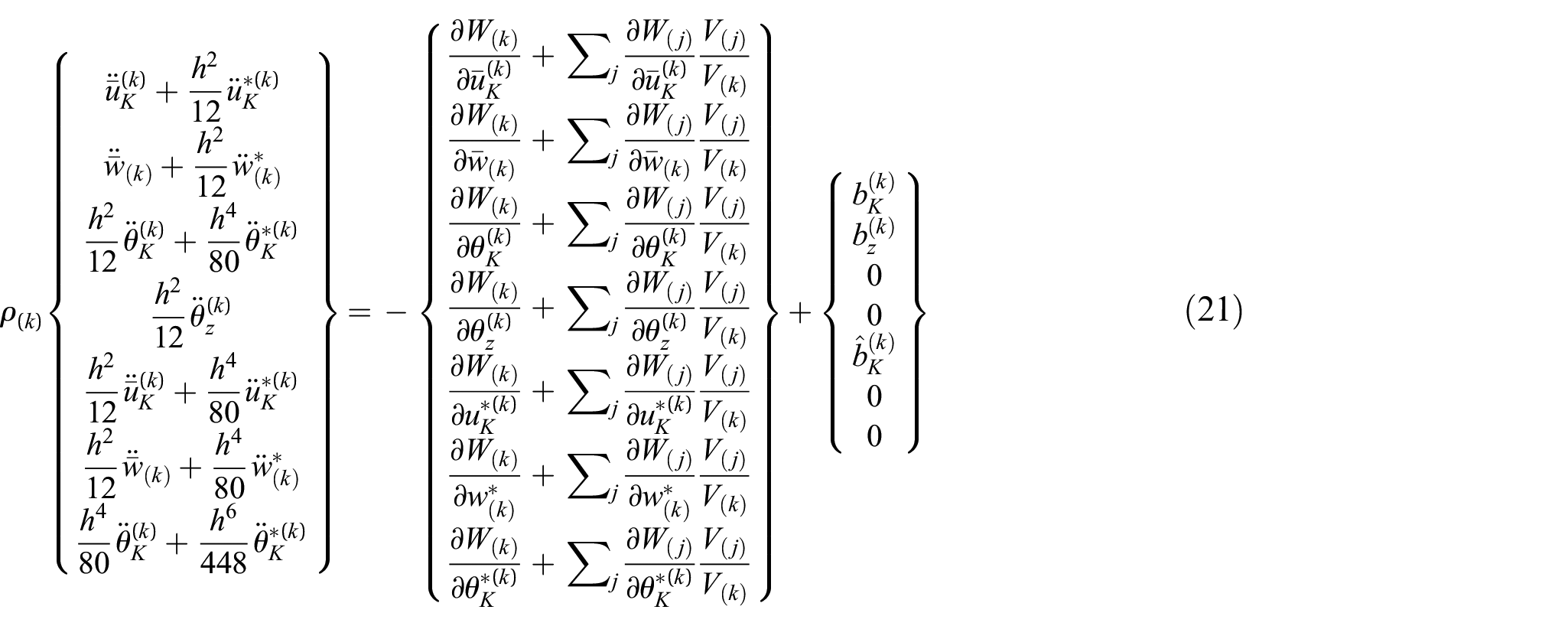
The peridynamic form of equations of motion can be obtained by utilizing Euler–Lagrange’s formulation as:
where the parameter represents the Lagrangian which can be represented by using kinetic energy, and total potential energy, as . The parameter is the generalized displacement vector which is defined as
The areal kinetic energy density of the body, is expressed as
Substituting equation (2) into equation (15) results in
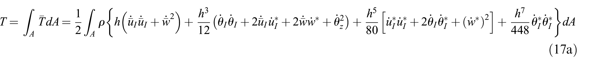
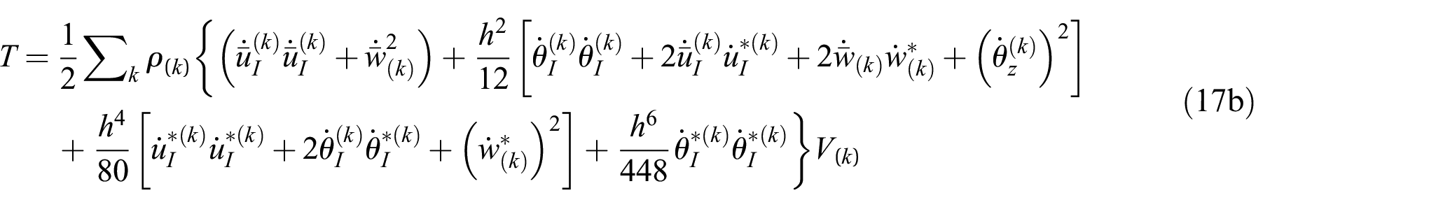
By integrating equation (15) over the whole mid-plane, total kinetic energy is obtained as
where denotes the volume of material particle and the summation symbol in equation (17b) refers to all material points inside the body.
In peridynamics theory, the SED at each material particle has non-local character. Therefore, SED at particle depends on the deformation fields of particle and other material particles in its interaction domain. Therefore, in general the SED function can be demonstrated as
in which i=1, 2, 3, … and indicates the ith family member of k.
The total potential energy, , is the summation of strain energy of all material particles and energy of external loads. Therefore, can be demonstrated as
where represents external force per volume
with , and representing external force per volume with respect to in-plane forces, transverse forces and bending moments, respectively.
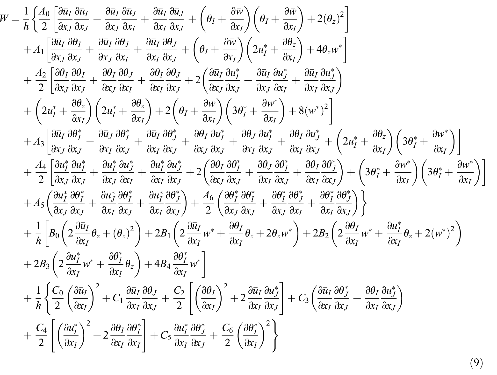
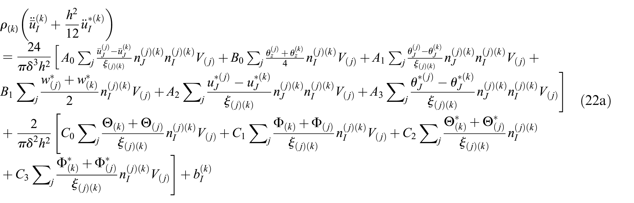
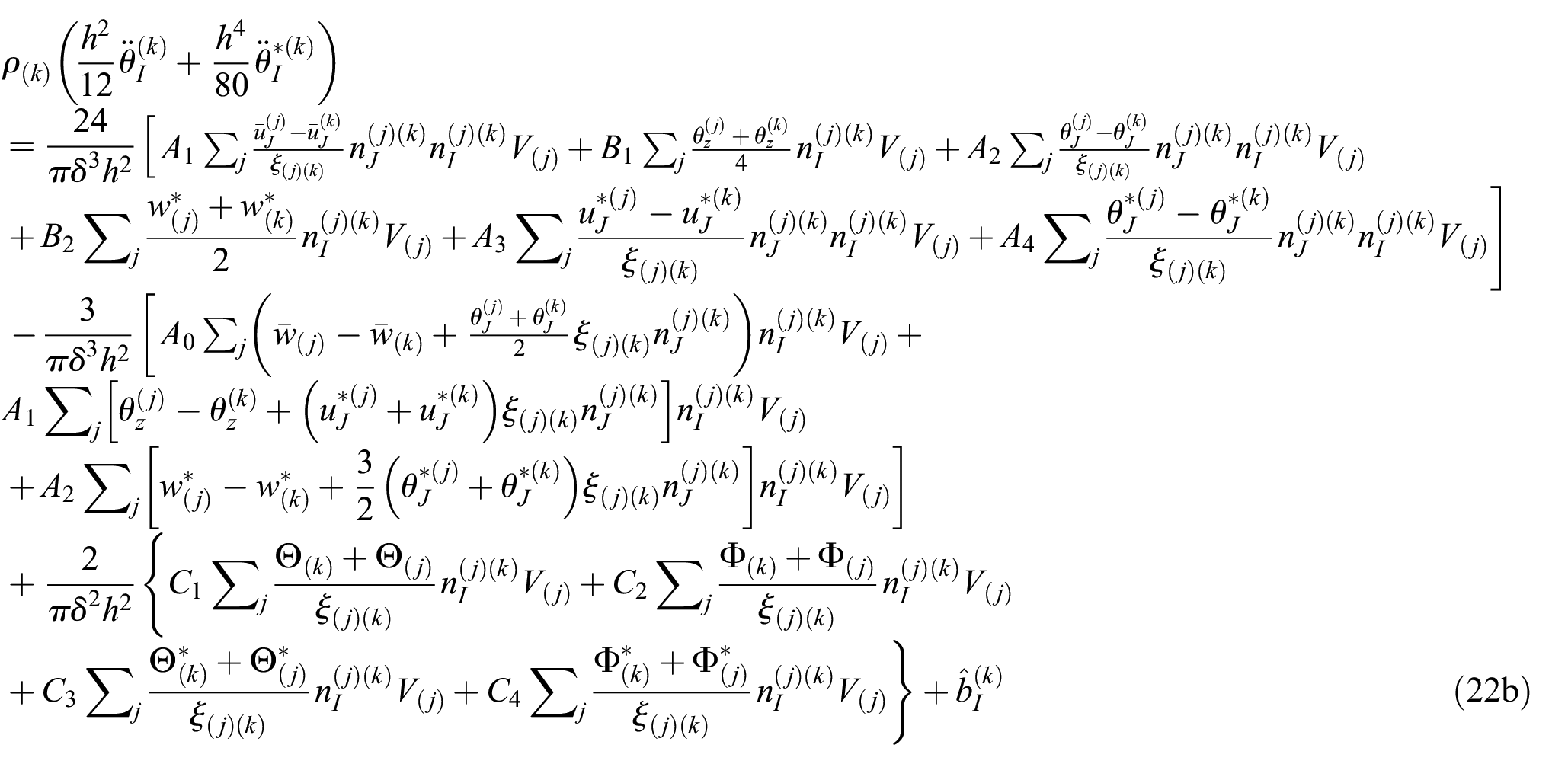
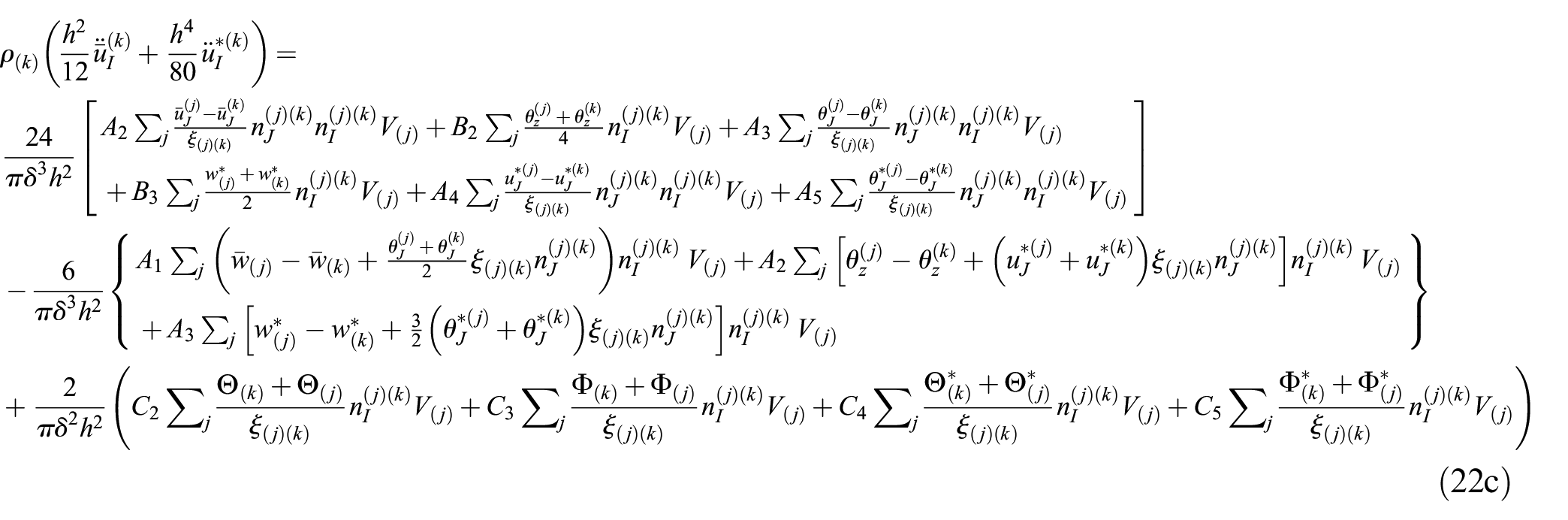
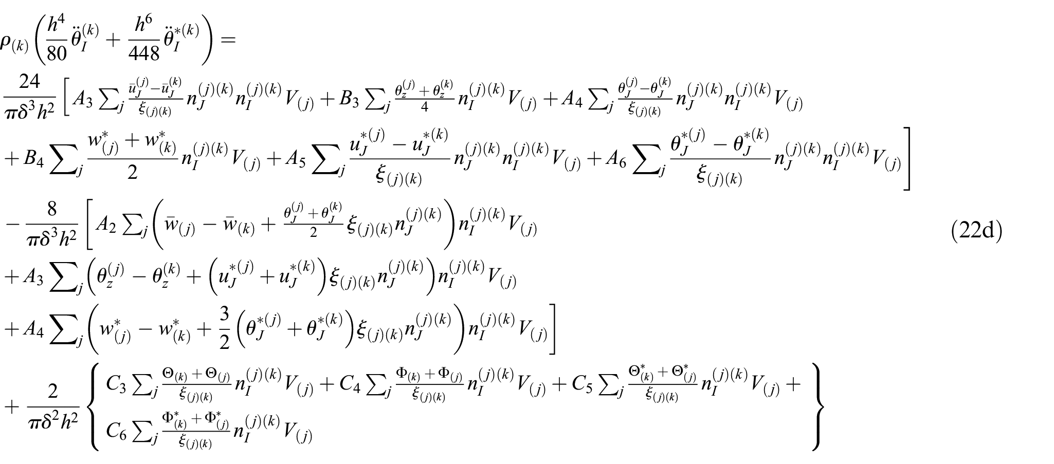
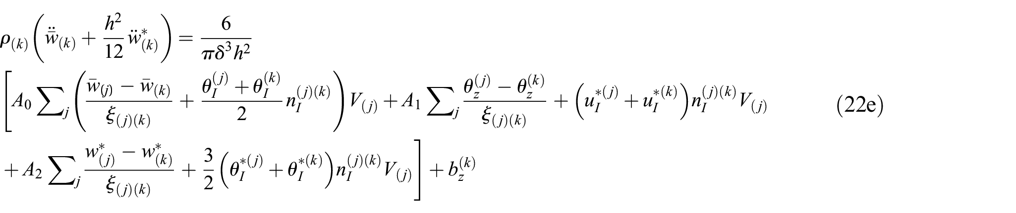
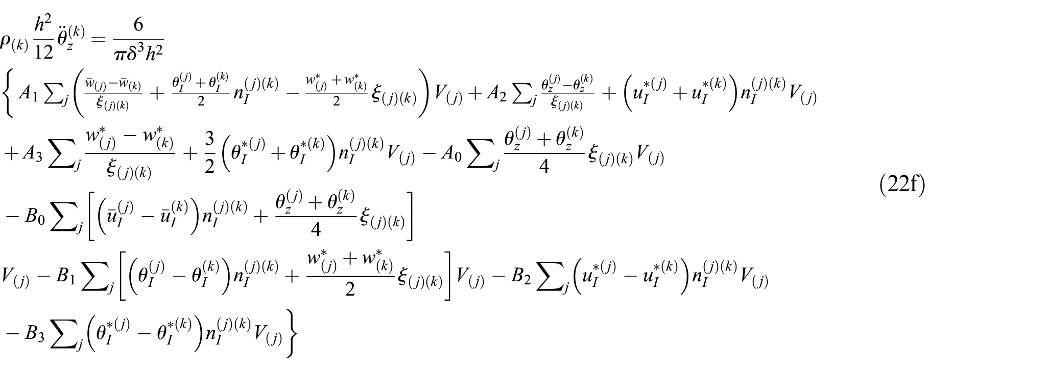
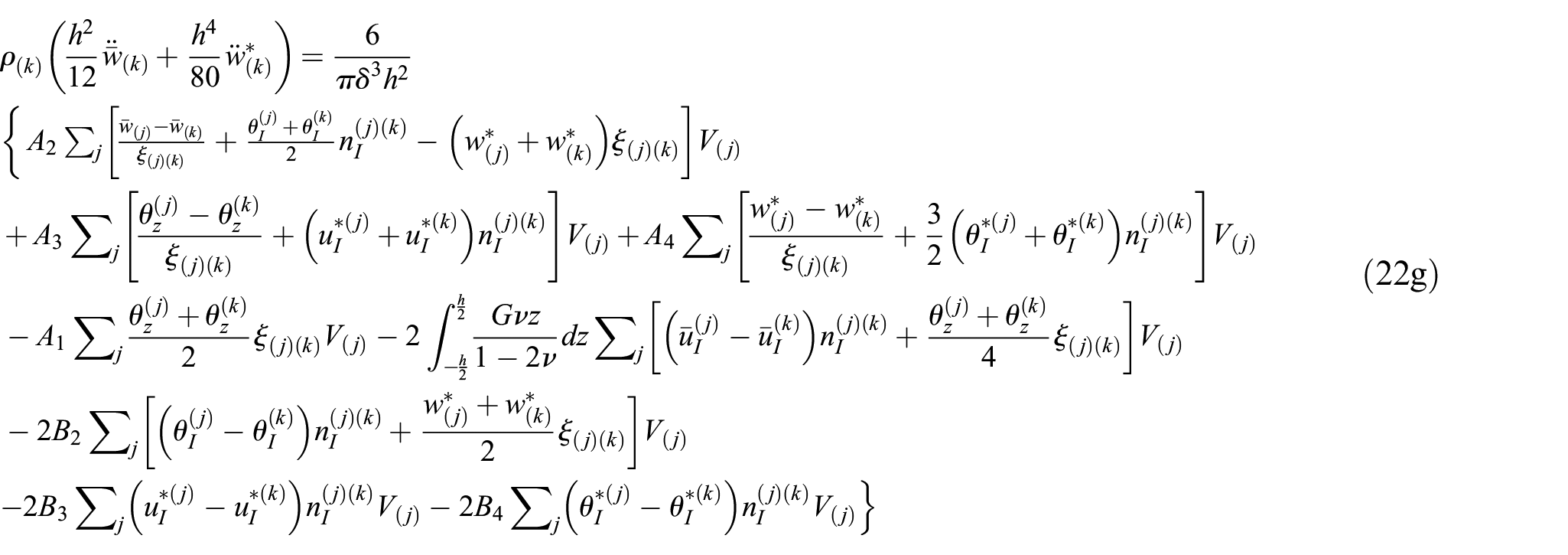
The derivation of the peridynamic form of SED given in equation (9) is presented in Appendix A. Substituting equations (A21), (A23) and (A29) into equation (21) results in the governing equations for higher-order functionally graded plates as
where the notations , , and appeared in equations (22a) to (22d) are defined as
Note that if Poisson’s ratio is , the coefficient to will equal to zero and equations (22a) to (22g) will reduce to bond-based peridynamics formulation.
4. Demonstrations of peridynamic HOP Formulation for FGMs
To demonstrate the developed HOP formulation for FGMs, the following functionally graded material properties are used:
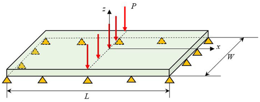
where denotes the plate thickness. The length, thickness and width of the plate are specified as , and m, respectively. The Young’s modulus at the top of the plate is and at the bottom of the plate is . For the peridynamic model, the discretization size is specified as . The interaction domain size is .
As reference solution, the corresponding finite element (FE) models are created in ANSYS by using SHELL181 and SOLID185 elements, respectively. The FE SHELL element model is generated with 50×50 elements and divided into 30 layers. On the other hand, the SOLID element model is obtained with 50×50 elements throughout the xy plane and 30 elements along the thickness. To obtain the functionally graded character, materials properties are assigned to the layers and elements through the thickness direction. The Young’s modulus varies gradually over the thickness from the first layer E1=101.67 GPa to the last layer E30=198.33 GPa. The Young’s modulus of nth layer can be expressed as . The Poisson’s ratio, ν=0.3, is applied for both models in ANSYS.
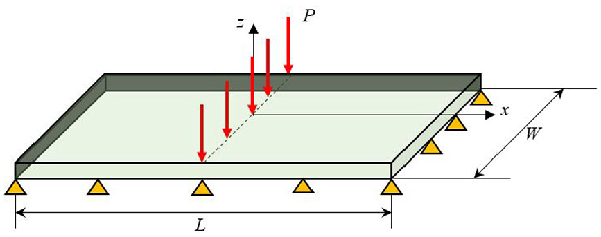
4.1. Transverse loading acting on a simply supported FGM plate
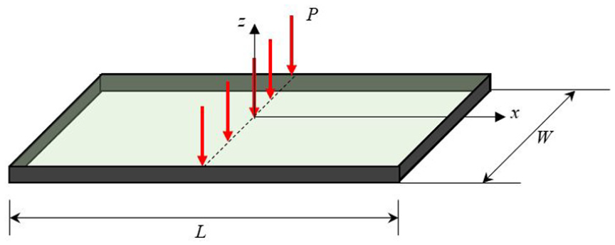
In this first numerical case a FGM plate with simply supports is considered, as shown in Figure 1. The FGM plate is exposed to a line load of along line at .
Simply supported FGM plate exposed to transverse line loading.
To impose simply supported boundary conditions, a fictitious region with a size of 2×horizon is introduced outside of the actual domain.
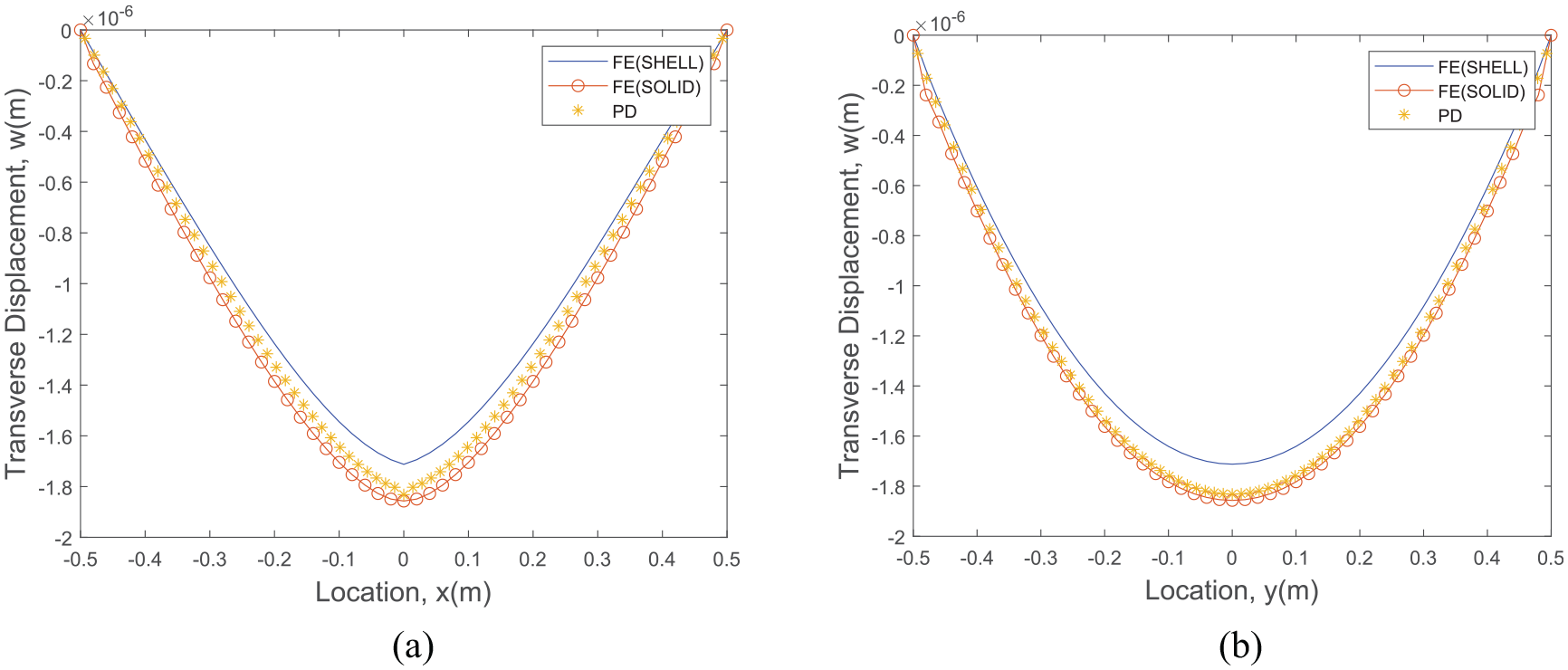
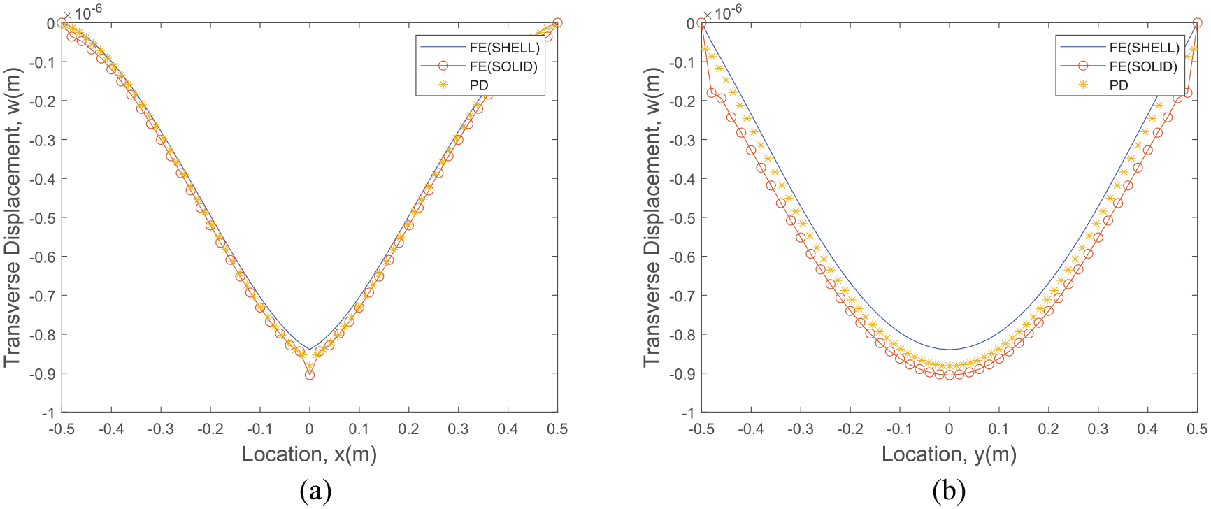
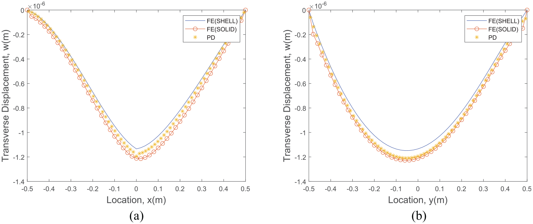
As shown in Figure 2, peridynamics predictions are compared against FEA solutions obtained by using ANSYS Solid and Shell elements. Note that ANSYS Shell element is based on classical Mindlin plate theory. Compared with ANSYS Shell element, the peridynamic higher-order formulation performs better and represents a similar deformation variation with respect to ANSYS Solid element.
Variation of transverse displacement alongside (a) x-axis, (b) y-axis.
4.2. Transverse loading acting on a clamped FGM plate
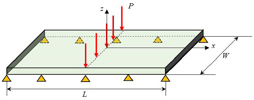
In this second case a FGM plate with clamped supports is considered, as shown in Figure 3. The FGM plate is exposed to a line load of along line at .
Clamped FGM plate exposed to transverse line loading.
To impose clamped boundary conditions, a fictitious region with a size of 2×horizon is introduced.
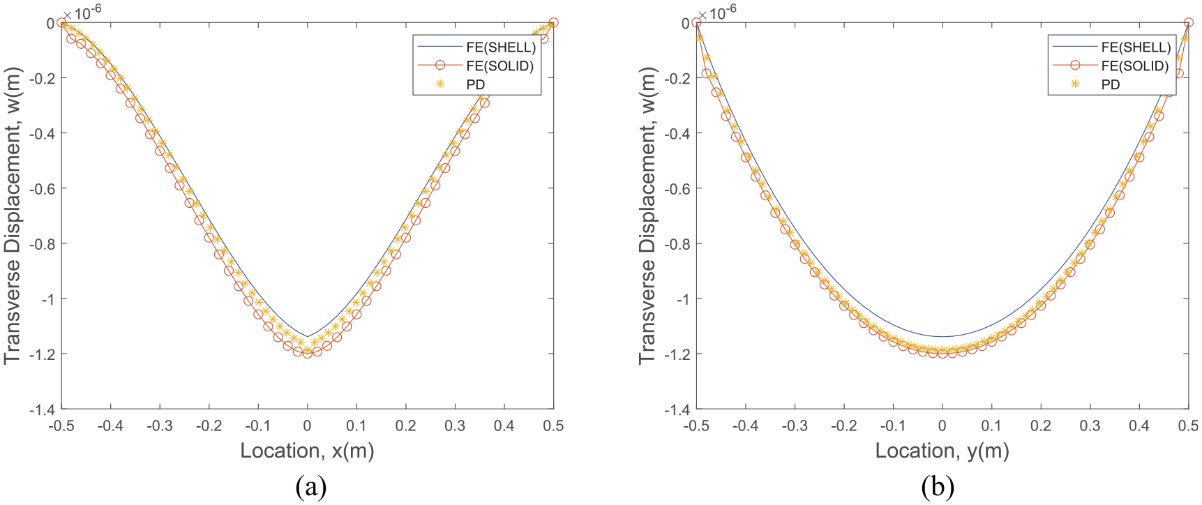
As shown in Figure 4, peridynamic predictions are compared against FEA solutions obtained by using ANSYS Solid and Shell elements. Compared with ANSYS Shell element, the peridynamic higher-order formulation performs better and represents a similar deformation variation with respect to ANSYS Solid element.
Variation of transverse displacement alongside (a) x-axis, (b) y-axis.
4.3. Transverse loading acting on a clamped – simply support – clamped – simply support (mixed boundary conditions) FGM plate
In this third case, a FGM plate with clamped – simply support – clamped – simply support is considered, as shown in Figure 5. The FGM plate is exposed to a line load of along line at .
FGM plate with Clamped – Simply Support – Clamped – Simply Support exposed to transverse line loading.
As shown in Figure 6, peridynamic predictions are compared against FEA solutions obtained by using ANSYS Solid and Shell elements. Compared with ANSYS Shell element, the peridynamic higher-order formulation performs better and represents a similar deformation variation with respect to ANSYS Solid element.
Variation of transverse displacement alongside (a) x-axis, (b) y-axis.
4.4. Transverse loading acting on a clamped – clamped – simply support – simply support FGM plate
In this fourth case a FGM plate with Clamped – Clamped – Simply Support – Simply Support is considered, as shown in Figure 7. The FGM plate is exposed to a line load of along line at .
FGM plate with Clamped – Clamped – Simply Support – Simply Support exposed to transverse line loading.
As shown in Figure 8, peridynamic predictions are compared against FEA solutions obtained by using ANSYS Solid and Shell elements. Compared with ANSYS Shell element, the peridynamic higher-order formulation performs better and represents a similar deformation variation with respect to ANSYS Solid element.
Variation of transverse displacement alongside (a) x-axis, (b) y-axis.
5. Conclusions of peridynamic HOP formulation for FGMs
In this paper, a novel HOP Formulation for FGMs in a peridynamic framework is developed. Plates with various thicknesses can be analysed with the developed formulation. Moreover, the usage of shear correction factor is eliminated. Taylor’s expansion and Euler–Lagrange formulation are used for obtaining governing equations. Four different numerical examples are considered for simply supported, clamped and mixed boundary conditions. In all these cases, variation of transverse deflections is obtained from both peridynamics and FEAs by using both solid and shell elements. In all cases, it is shown that newly developed peridynamic HOP formulation performed better with respect to Shell element that uses Mindlin plate formulation, which demonstrates the capability and accuracy of the newly developed formulation.
Footnotes
Appendix
As explained in section 2, the classical strain energy function of the higher-order functionally graded plate can be written as
Equation (A1a) can be separated into three parts for simplification as
where
and
Next, Taylor’s expansion will be utilised to determine the corresponding peridynamic forms of equations (A2a) to (A2c).
Funding
The author(s) received no financial support for the research, authorship, and/or publication of this article.
ORCID iD
Erkan Oterkus
References
1.
QianLFBatraRC.Transient thermoelastic deformations of a thick functionally graded plate. J Therm Stress2004; 27: 705–740.
2.
FerreiraAJMBatraRCRoqueCMCQianLFMartinsPALS.Static analysis of functionally graded plates using third-order shear deformation theory and a meshless method. Compos Struct2005; 69: 449–457.
3.
ChengZQBatraRC.Deflection relationships between the homogeneous Kirchhoff plate theory and different functionally graded plate theories. Arch Mechan2000; 52: 143–158.
4.
BatraRC.Higher-order shear and normal deformable theory for functionally graded incompressible linear elastic plates. Thin Wall Struct2007; 45: 974–982.
5.
BelabedZHouariMSATounsiAMahmoudSRBégOA.An efficient and simple higher order shear and normal deformation theory for functionally graded material (FGM) plates. Compos B Eng2014; 60: 274–283.
6.
XiangSKangGW.A nth-order shear deformation theory for the bending analysis on the functionally graded plates. Eur J Mech Solid2013; 37: 336–343.
SillingSA.Reformulation of elasticity theory for discontinuities and long-range forces. J Mech Phys Solid2000; 48: 175–209.
9.
KulkarniSSTabarraeiA.An ordinary state based peridynamic correspondence model for metal creep. Eng Fract Mech2020; 107042.
10.
ShiCGongYYangZGTongQ.Peridynamic investigation of stress corrosion cracking in carbon steel pipes. Eng Fract Mech2019; 219: 106604.
11.
ZhanJMYaoXHHanF.An approach of peridynamic modeling associated with molecular dynamics for fracture simulation of particle reinforced metal matrix composites. Compos Struct2020; 250: 112613.
12.
DorduncuM.Stress analysis of laminated composite beams using refined zigzag theory and peridynamic differential operator. Compos Struct2019; 218: 193–203.
13.
BuryachenkoVA.Generalized effective fields method in peridynamic micromechanics of random structure composites. Int J Solid Struct2020; 202: 765–786.
14.
HuYLYuYMadenciE.Peridynamic modeling of composite laminates with material coupling and transverse shear deformation. Compos Struct2020; 253: 112760.
15.
OterkusEBarutAMadenciE.Damage growth prediction from loaded composite fastener holes by using peridynamic theory. In: 51st AIAA/ASME/ASCE/AHS/ASC Structures, Structural Dynamics, and Materials Conference 18th AIAA/ASME/AHS Adaptive Structures Conference 12th, 2010, pp. 3026.
16.
OterkusEMadenciE. Peridynamics for failure prediction in composites. In: 53rd AIAA/ASME/ASCE/AHS/ASC Structures, Structural Dynamics and Materials Conference 20th AIAA/ASME/AHS Adaptive Structures Conference 14th, 2012, pp. 1692.
17.
BazazzadehSMossaibyFShojaeiA.An adaptive thermo-mechanical peridynamic model for fracture analysis in ceramics. Eng Fract Mech2020; 223: 106708.
18.
WangYZhouXZhangT.Size effect of thermal shock crack patterns in ceramics: Insights from a nonlocal numerical approach. Mech Mater2019; 137: 103133.
19.
GuskiVVerestekWOterkusESchmauderS.Microstructural investigation of plasma sprayed ceramic coatings using peridynamics. J Mech2020; 36: 183–196.
20.
HuangDZhangQQiaoP.Damage and progressive failure of concrete structures using non-local peridynamic modeling. Sci China Technol Sci2011; 54: 591–596.
21.
GerstleWSauNSillingS.Peridynamic modeling of concrete structures. Nucl Eng Des2007; 237: 1250–1258.
22.
GuXZhangQHuangDYvY.Wave dispersion analysis and simulation method for concrete SHPB test in peridynamics. Eng Fract Mech2016; 160: 124–137.
23.
OterkusEGuvenIMadenciE.Impact damage assessment by using peridynamic theory. Open Eng2012; 2: 523–531.
24.
ChengZQSuiZBYinHYuanCFChuLS.Studies of dynamic fracture in functionally graded materials using peridynamic modeling with composite weighted bond. Theor Appl Fract Mech2019; 103: 102242.
25.
ChengZFuZZhangYWuH.A peridynamic model for analyzing fracture behavior of functionally graded materials used as an interlayer. Acta Mech Solida Sinica2020; 1–12.
26.
YangZOterkusEOterkusS.Analysis of functionally graded Timoshenko beams by using peridynamics. J Peridynam Nonlocal Model2020; 1–19.
27.
OzdemirMKefalAImachiMTanakaSOterkusE.Dynamic fracture analysis of functionally graded materials using ordinary state-based peridynamics. Compos Struct2020; 112296.
28.
WangHOterkusEOterkusS.Predicting fracture evolution during lithiation process using peridynamics. Eng Fract Mech2018; 192: 176–191.
29.
De MeoDOterkusE. Finite element implementation of a peridynamic pitting corrosion damage model. Ocean Eng2017; 135: 76–83.
30.
O’GradyJFosterJ.Peridynamic beams: A non-ordinary, state-based model. Int J Solid Struct2014; 51: 3177–3183.
31.
DiyarogluCOterkusEOterkusS.An Euler–Bernoulli beam formulation in an ordinary state-based peridynamic framework. Math Mech Solid2019; 24: 361–376.
32.
YangZOterkusENguyenCTOterkusS.Implementation of peridynamic beam and plate formulations in finite element framework. Continuum Mech Therm2019; 31: 301–315.
VazicBOterkusEOterkusS.Peridynamic model for a Mindlin plate resting on a Winkler elastic foundation. J Peridynam Nonlocal Model2020; 1–10.
35.
TaylorMSteigmannDJ.A two-dimensional peridynamic model for thin plates. Math Mech Solid2015; 20: 998–1010.
36.
O’GradyJFosterJ.Peridynamic plates and flat shells: A non-ordinary, state-based model. Int J Solid Struct2014; 51: 4572–4579.
37.
DiyarogluCOterkusEOterkusSMadenciE.Peridynamics for bending of beams and plates with transverse shear deformation. Int J Solid Struct2015; 69: 152–168.
38.
DiehlPPrudhommeSLévesqueM.A review of benchmark experiments for the validation of peridynamics models. J Peridynam Nonlocal Model2019; 1: 14–35.