Functionally graded materials are a potential alternative to traditional fibre-reinforced composite materials as they have continuously varying material properties which do not cause stress concentrations. In this study, a state-based peridynamic model is presented for functionally graded Kirchhoff plates. Equations of motion of the new formulation are obtained using the Euler–Lagrange equation and Taylor’s expansion. The formulation is verified by considering several benchmark problems including a clamped plate subjected to transverse loading and a simply supported plate subjected to transverse loading and inclined loading. The material properties are chosen such that Young’s modulus is assumed to be varied linearly through the thickness direction and Poisson’s ratio is constant. Peridynamic results are compared against finite element analysis results, and a very good agreement is obtained between the two approaches.
Functionally graded materials (FGMs) are a potential alternative to traditional fibre-reinforced composite materials (FRCMs) as they have continuously varying material properties which do not cause stress concentrations. Such stress concentrations arise in FRCMs and cause delamination-type failure. With the advancement of additive manufacturing technologies, it is expected that the usage of FGMs will increase in the near future.
There are many studies in the literature focusing on analysis of FGMs. Amongst these Vel and Batra [1] presented three-dimensional exact solutions for free and forced vibrations of simply supported functionally graded plates using a power series method and considering classical plate theory, first-order shear deformation theory and third-order shear deformation theory. Zenkour [2] studied the bending deformation of a simply supported functionally graded plate subjected to transverse uniform load by using generalised shear deformation theory without using shear correction factors. Shen [3] performed nonlinear bending analysis for simply supported functionally graded plates subjected to transverse loading by taking into account the effect of temperature and using Reddy’s higher-order shear deformation plate theory. Bian et al. [4] utilised a plate theory using the concept of shape function of the transverse coordinate parameter to investigate functionally graded plates subjected to cylindrical bending. Carrera et al. [5] examined the effect of thickness stretching in functionally graded plates by utilising Carrera’s Unified Formulation. As an alternative formulation, a new continuum mechanics formulation, peridynamics (PD), can be utilised.
PD was introduced by Silling [6] to overcome the limitations of Classical Continuum Mechanics. Governing equations of PD is in the form of integro-differential equations and does not contain spatial derivatives. Therefore, these equations are still valid even if the displacement field is discontinuous due to existence of cracks. Moreover, PD is a non-local continuum mechanics formulation and it has a length-scale parameter, horizon, which defines range of non-local interactions between material points. PD has been used for analysing different types of materials including metals and composites [7–10] and is suitable for multiphysics analysis [11–15]. Moreover, several peridynamic formulations are available in the literature to analyse beams, plates and shells [16–21].
In this study, PD is utilised to investigate the bending behaviour of functionally graded plates based on Kirchhoff plate theory for the first time in the literature. The governing equations are obtained by using Euler–Lagrange equation and Taylor’s expansion. Several benchmark problems are considered to validate the newly developed formulation.
2. Functionally graded Kirchhoff plate
Kirchhoff developed a complete and adequate set of equation for linear theory of thin plates. According to the Kirchhoff plate theory, it is assumed that a transverse normal to the mid-surface in the undeformed state remains straight, normal to the mid-surface and it has no change in length during deformation. Moreover, the displacement field of any material point can be represented in terms of the displacement field of the material points at the mid-surface as
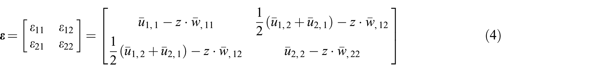
where , and denote the displacement of a material point at the mid-surface in x), ) and z directions, respectively. Thus, the strain-displacement relationships can be written as
in which and represent the rotation angles of a particular material point at the mid-surface which can be expressed in terms of from equations (2e) and (2f) as
and
Therefore, eliminating and , strain components in a thin plate can be easily represented in terms of only three mid-surface parameters, , and , as
or
where the indices and vary from 1 to 2. Note that from this stage, for the sake of conciseness, the notation ‘’overbar”, , will be removed from displacement components.
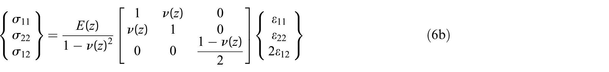
Plane stress constitutive relation is held in the thin plate of functionally graded material as
and
where and represent elastic modulus and Poisson’s ratio, respectively, and both of them vary in the thickness direction z. Equation (6b) can also be written in indicial notation as
where is the components of the material property tensor and it is defined as
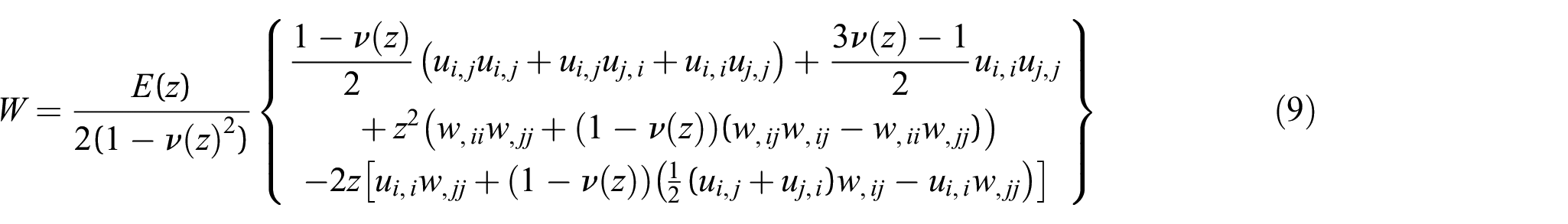
The linear elastic strain energy density of the plate can be expressed as
Substituting equations (6) and (7) into equation (8) and rearranging the terms results in
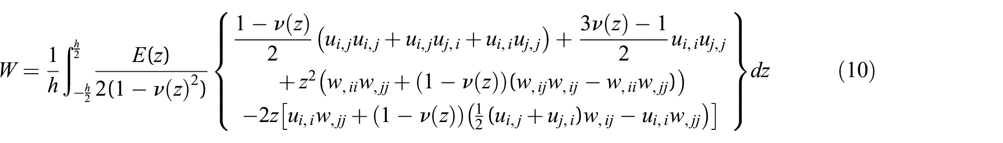
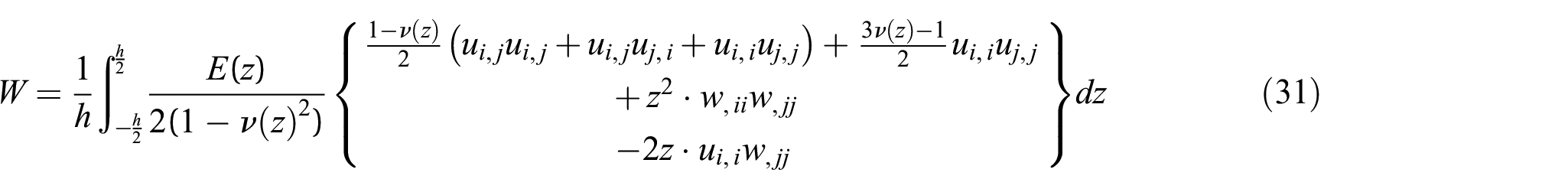
As the strain energy density changes in the thickness direction, the average strain energy density can be obtained by integrating equation (9) over the thickness and dividing by thickness, which yields
Note that equation (10) is composed of three independent parts. The first and second rows represent the strain energy densities that occur due to in-plane and flexural (bending) deformation, respectively, and the last row arises due to coupling of in-plane and flexural deformations. If the material properties are constant over the thickness, the last row of equation (10) will be cancelled out after integration and equation (10) will become uncoupled. Thus, the strain energy density of the plate can be written concisely as
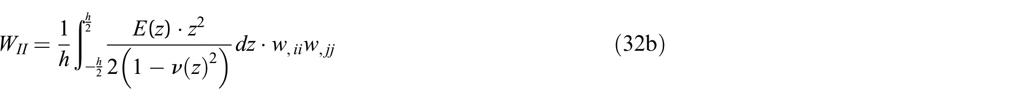
where , and denote the strain energy densities due to in-plane deformation, flexural deformation and coupled deformation, respectively, which can be written as
3. Peridynamic formulation for functionally graded Kirchhoff plate
PD is a non-local theory, which is different than the classical local continuum theory, as the state of each material point is not only influenced by the material points located in its immediate vicinity but is also influenced by material points which are located within a region of a finite radius named as ‘horizon’, . The equation of motion in PD can be written as
where and t represent density and time, respectively, and denote displacement and is the body load vector. In equation (13), represents the interaction (bond) force vector between material points located at and . The closed-form solution to equation (13) is generally not available. Numerical approaches such as the meshless approach are widely used to solve equation (13). Therefore, the PD equations of motion for a particular material point can be expressed in summation form as
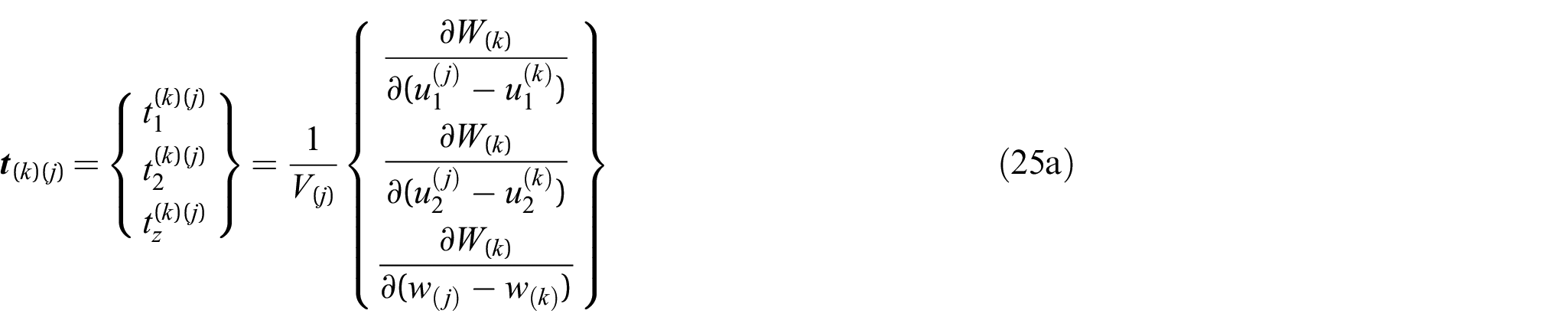
where indicates the total number of material points inside the horizon of the material point, k. The interaction force vector, , between material points and is defined as
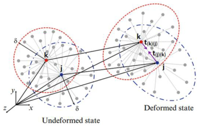
As shown in Figure 1, the PD force density vector represents the force acting on the main material point by its family member material point , and, on the contrary, represents the force acting on material point by its family member material point, .
Peridynamic interaction force between material points [22].
Unlike the classical elasticity theory, according to PD theory, the strain energy density function of a particular material point depends on the relative displacement between and all other material points in its horizon which can be expressed as
where is the displacement vector of point and () is the displacement vector of the th material point within the horizon of the material point .
The total potential energy stored in the body can be obtained by summing potential energies of all material points including strain energy and energy due to external loads as
where is the body load vector of the material point with a unit of ‘force per unit volume’. Similarly, the total kinetic energy of the body can be obtained by summing kinetic energies of all material points as
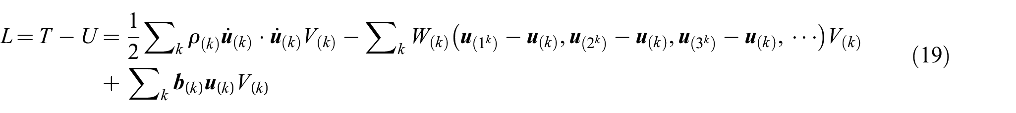
Thus, the Lagrangian of the body can be expressed as
Utilising the Lagrangian term given in equation (19), the equations of motion can be obtained from Euler–Lagrange equation as
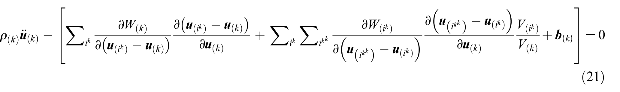
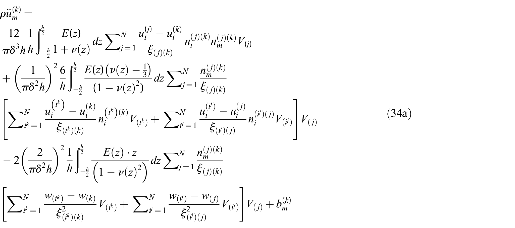
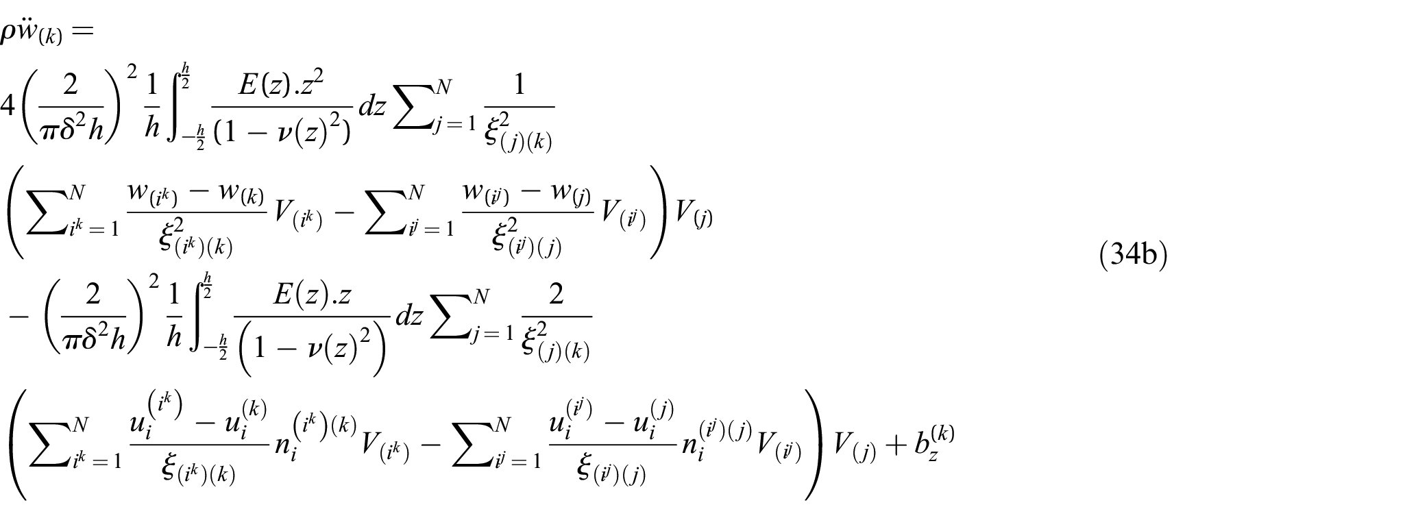
which yields
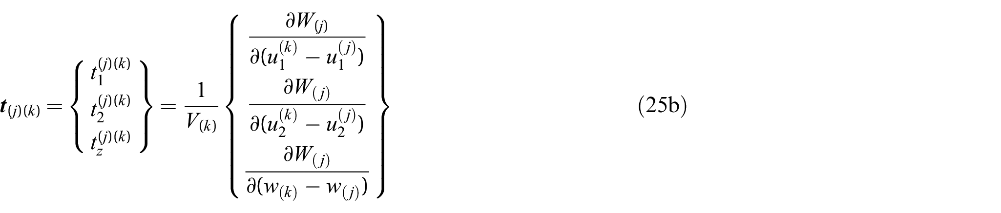
where point is a family member of the material point and similarly point is a family member of the material point . Note that the following relationship holds
where , and are the components of the displacement vector.
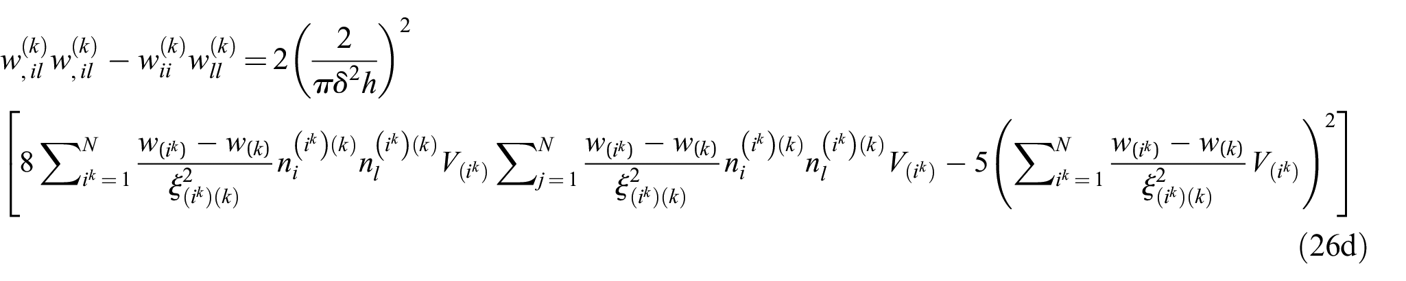
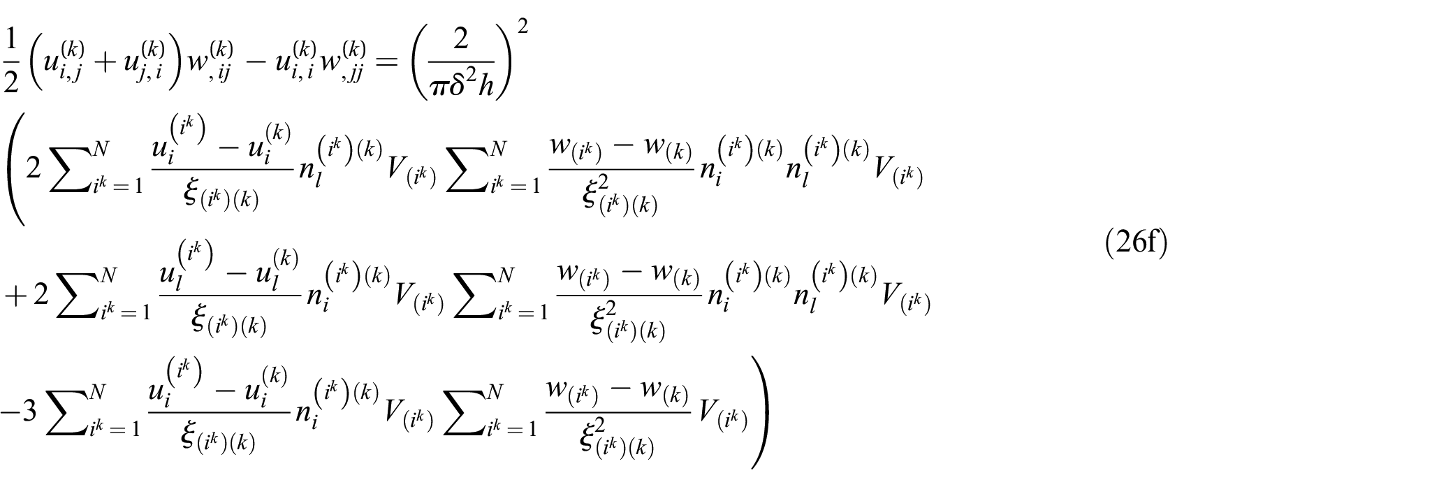
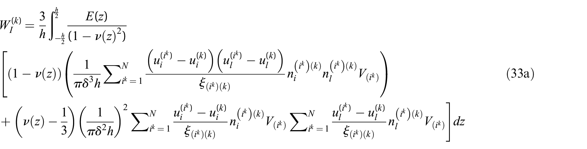
The strain energy density function given in equation (12) can be written in PD form for the material point . This can be achieved by transforming all differential terms into the equivalent form of integration. As derived in Appendix A, the partial differential terms in equation (12) for the material point k can be expressed in PD form as
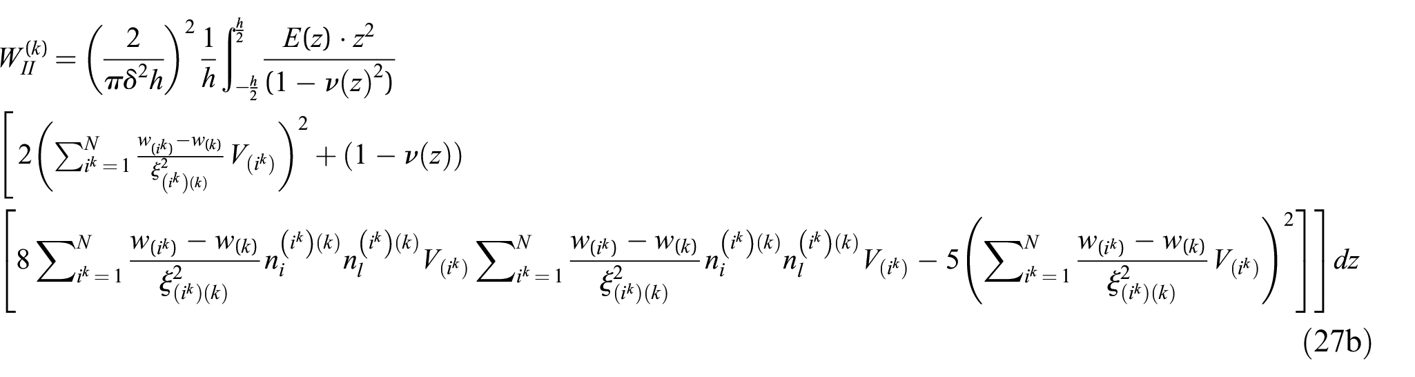
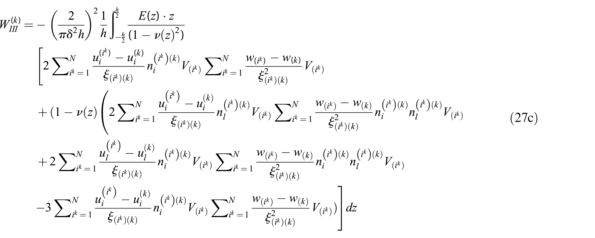
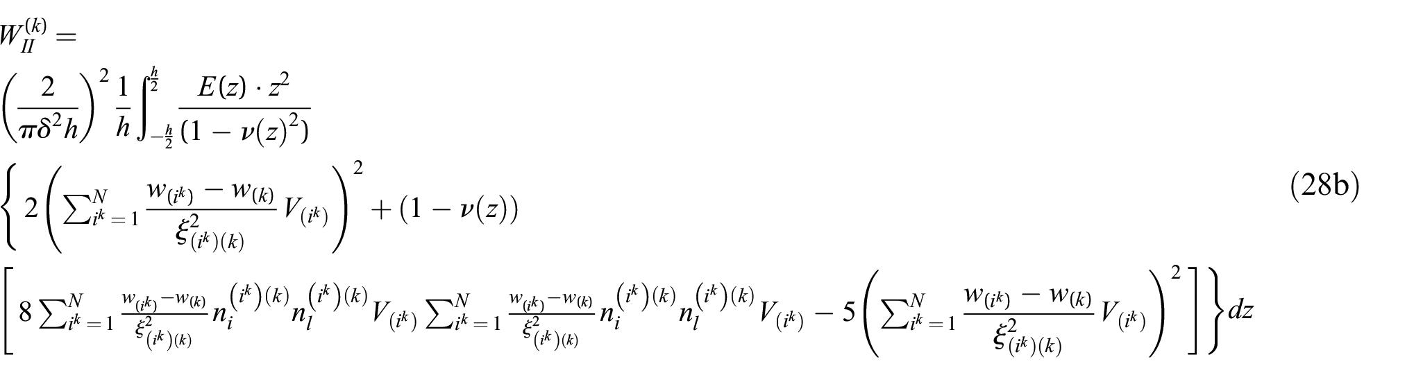
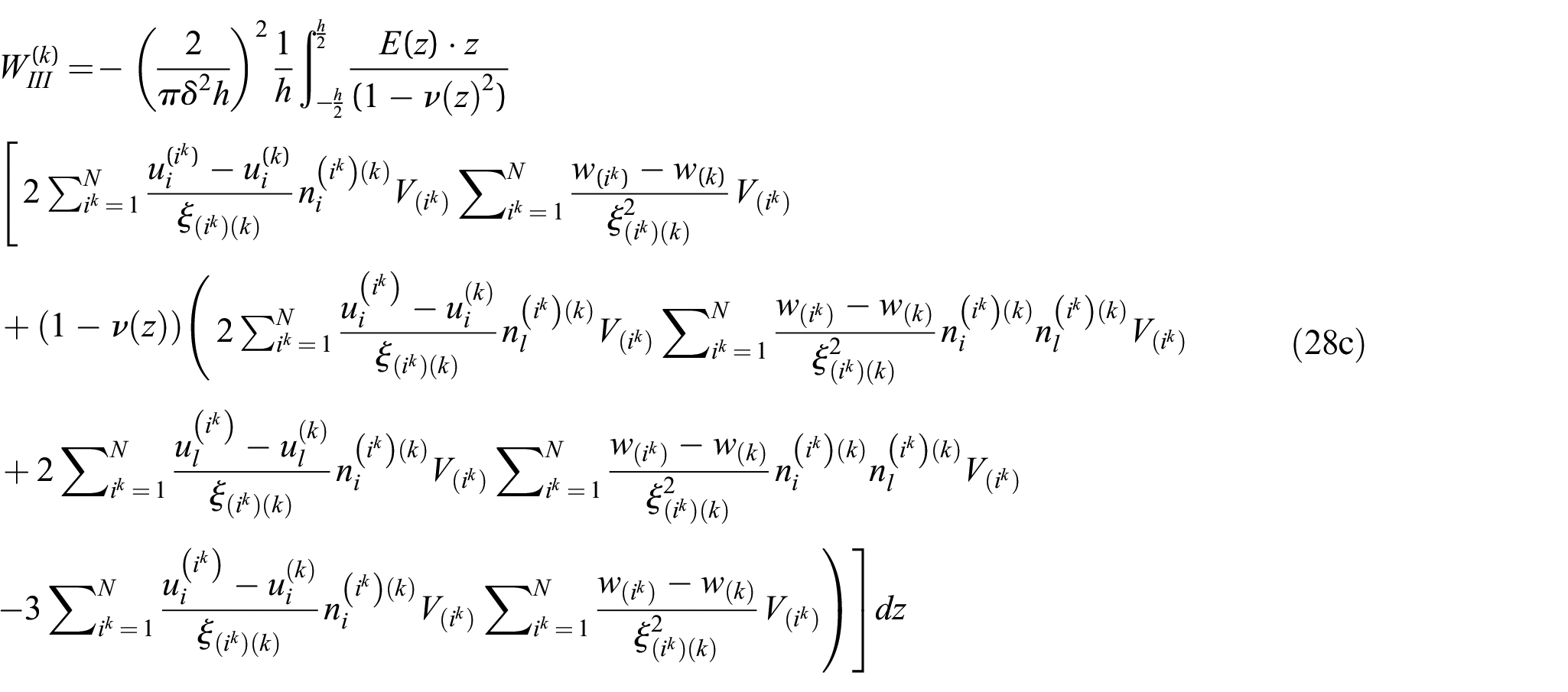
where with being the bond angle with respect to x-axis. Substituting the relationships given in equations (26a–f) in equation (12), the strain energy density components for the material point can be written in PD form as
By changing the indices in equations (27a–c), the strain energy density of the material point j, which is a family member of the material point k, can be written as
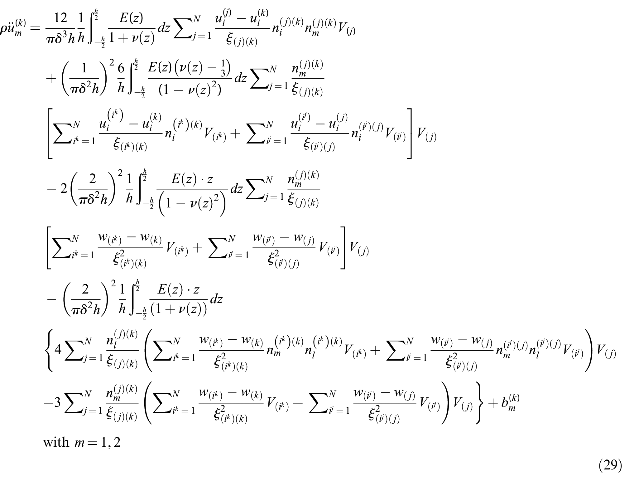
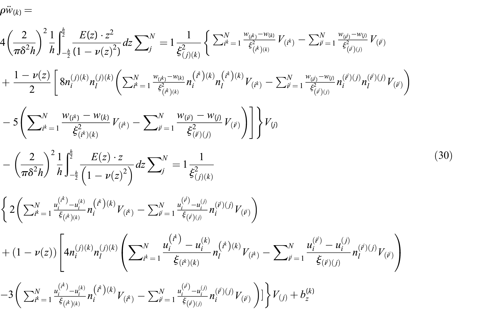
After substituting equations (27) and (28) into equations (11) and (23) and performing some algebraic manipulations, the PD equation of motion can be written in terms of displacements only as
and
In the particular case of our study, when the plate is subjected to a constraint condition on all edges, i.e. no free edges, the strain energy density function of a particular material point of the plate can be considerably simplified, as explained in Appendix B, and takes the following form as
with
Corresponding PD form for the material point can be written as
which can also be written concise form as
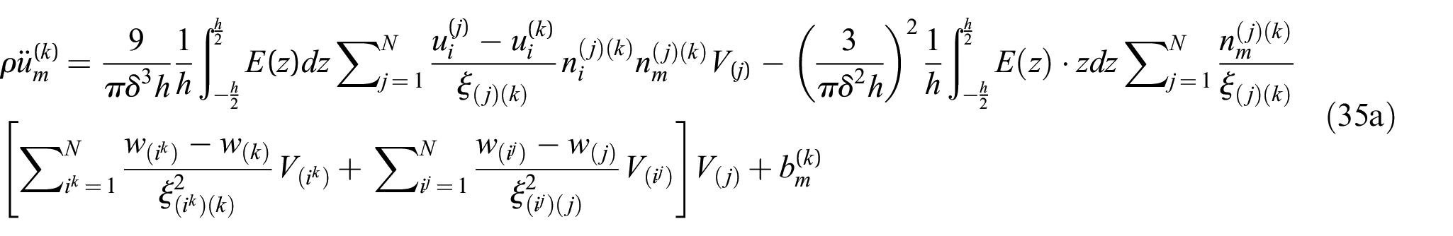
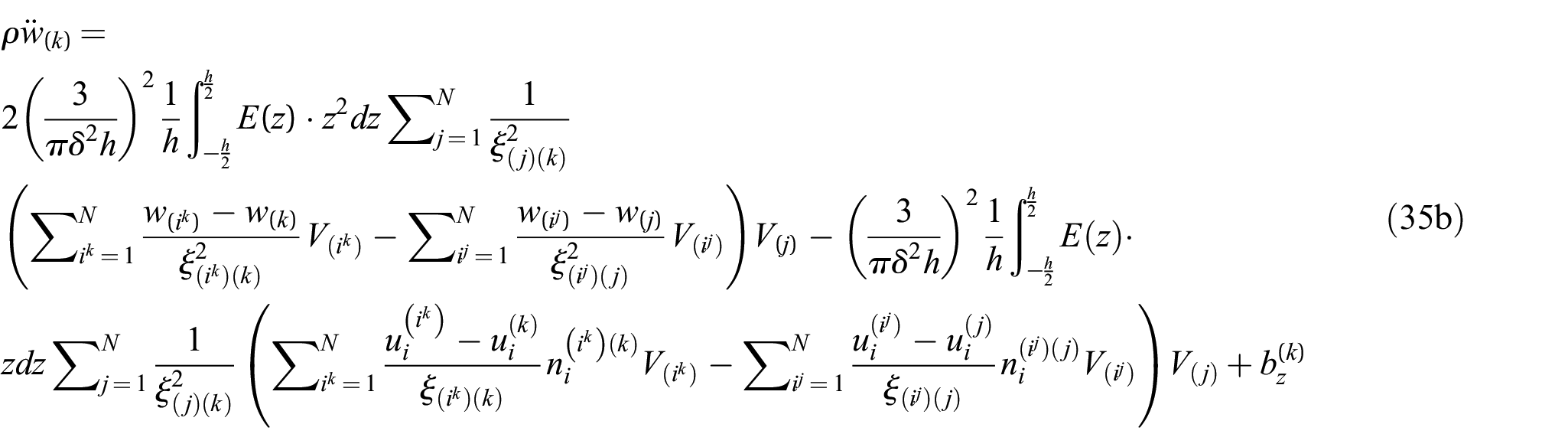
Note that if the Poisson’s ratio is considered as a constant value, , then the PD equations will further simplify as
4. Numerical results
To demonstrate the validity of the presented PD formulation for functionally graded Kirchhoff plates, the PD solutions are compared with the corresponding finite element (FE) analysis results. Here, the material properties are chosen such that Young’s modulus, , is assumed to be varied linearly through the thickness direction and Poisson’s ratio, , remains a constant as
and
where and denote the Young’s modulus of the top and bottom surfaces of the plate, and represents the total thickness of the plate.
4.1. Clamped plate subjected to transverse loading
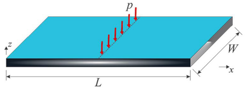
A clamped functionally graded plate with a length and width of and a thickness of is considered, as shown in Figure 2. The Poisson’s ratio of the plate is and the Young’s modulus of the top and bottom surfaces are and , respectively. The model is discretised into one single row of material points along the thickness direction and the distance between material points is . A fictitious region is introduced outside the edges as the external boundaries with a width of . The plate is subjected to a distributed transverse load of through the y-centre line, respectively. The line load is converted to a body load of and it is distributed to one column of material volumes through the central line.
Clamped plate subjected to transverse loading.
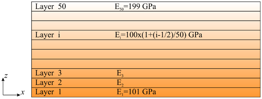
The FE model of the plate is created by using the SHELL181 element in ANSYS with dimensions of . To model the functionally graded plate, the model is divided to 50 layers with varying homogeneous materials properties through the thickness. The Young’s modulus varies linearly over the thickness from the first layer to the last layer , as shown in Figure 3. The model is meshed with 0.01 m element size.
Variation of the Young’s modulus in thickness direction for the FE model.
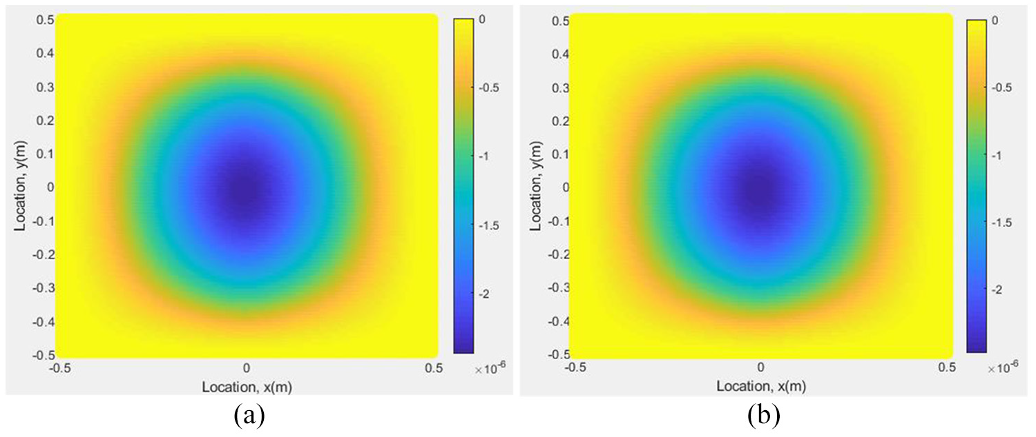
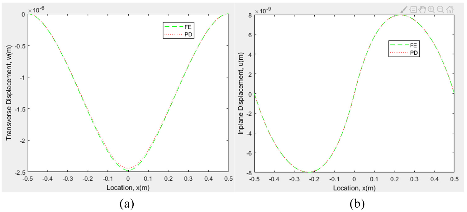
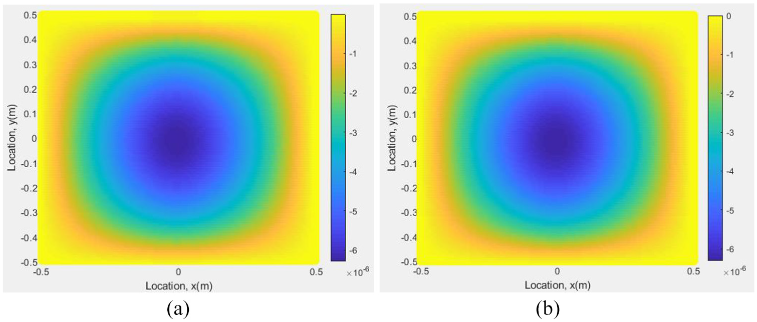
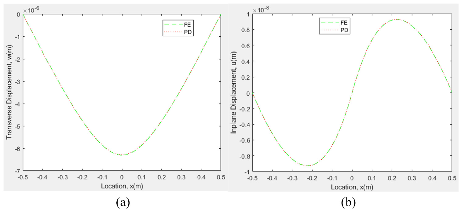
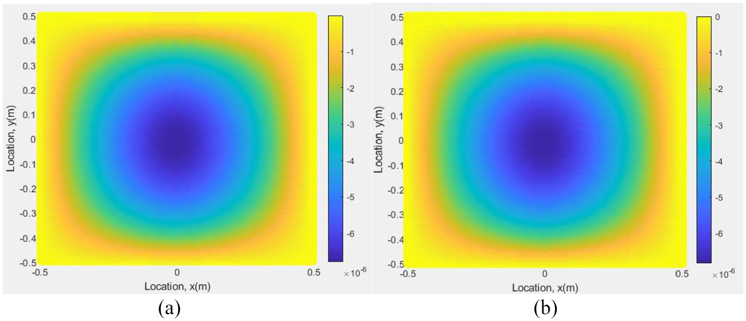
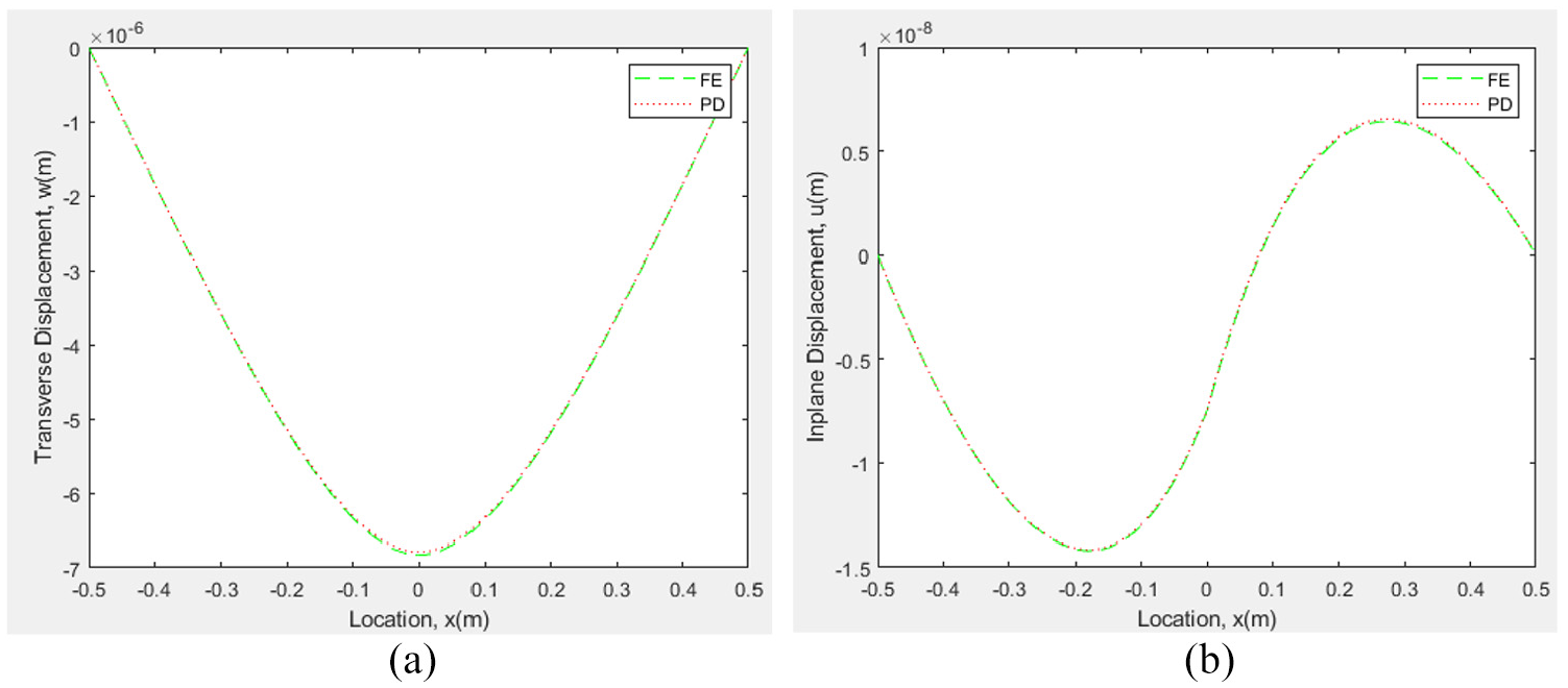
The PD and FE transverse displacement contours are compared in Figure 4. They yield similar displacement variations. The maximum difference between the PD and FE results is less than 0.5%. Moreover, the transverse and in-plane displacement components along the central y-axis are compared in Figure 5 and very good agreement is obtained between the two approaches. These results verify the accuracy of the current PD formulation for a functionally graded Kirchhoff plate theory under clamped boundary conditions.
Variation of transverse displacements (a) PD, (b) FEM.
Variation of (a) transverse, w and (b) in-plane, u1, displacements along the central y-axis.
4.2 Simply supported plate subjected to transverse loading
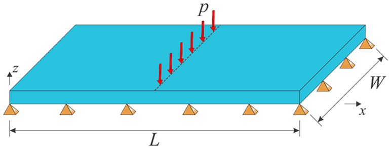
A simply supported plate (see Figure 6) has the same geometrical and material properties as in the clamped plate case. Again, it is discretised with a single row of material points along the thickness direction and the discretisation size is . A fictitious region is created outside the region of boundaries and its width is equal to two times the size of the horizon, . The plate is subjected to a distributed transverse line load of through the y-central line. It is imposed to central column of material points with a body load of .
Simply supported plate subjected to transverse loading.
The transverse displacement components of FE and PD theory show very close variations, as shown in Figure 7. The maximum difference between the PD and FE results is less than 0.5%. Furthermore, the transverse and in-plane displacement variations along the central y-axis are on top of each other for the FE and PD results, as shown in Figure 8. This confirms the current PD formulation of functionally graded plate theory under simply supported boundary conditions.
Variation of transverse displacements (a) PD, (b) FEM.
Variation of (a) transverse, w and (b) in-plane, u1, displacements along the central y-axis.
4.3 Simply supported plate subjected to inclined loading
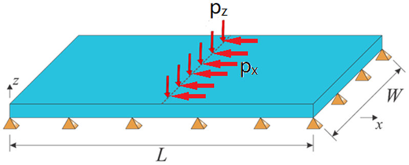
This problem case is similar to the previous case except Poisson’s ratio of 0.2 and an inclined load of through the y-central line are considered, as shown in Figure 9.
Simply supported plate subjected to inclined loading.
As depicted in Figure 10, the transverse displacement components of FE and PD theory agree very well with each other. Moreover, the transverse and in-plane displacements variations along the central y-axis are also in very good agreement, as depicted in Figure 11.
Variation of transverse displacements (a) PD, (b) FEM.
Variation of (a) transverse, w and (b) in-plane, u1, displacements along the central y-axis.
5. Conclusions
In this study, a state-based peridynamic model was presented for functionally graded Kirchhoff plates. Equations of motion of the new formulation were obtained by using Euler–Lagrange equations and Taylor’s expansion. The formulation was verified by considering several benchmark problems including a clamped plate subjected to transverse loading and simply supported plate subjected to transverse loading and inclined loading. The material properties were chosen such that Young’s modulus is assumed to be varied linearly through the thickness direction and Poisson’s ratio is constant. Peridynamic results were compared against FE analysis results and a very good agreement is obtained between the two approaches.
Footnotes
Appendix A
The in-plane displacement function can be expanded as Taylor series up to first order as
where , , and are defined as
Equation (A1) can be rewritten in indicial notation form as
Equation (A3a) can also be written with a different free index, as
which can be rewritten by multiplying both sides with as
If we suppose that the point is kept as a fixed point, multiplying both sides of equation (A5) by and integrating over a circular horizon with central point of and radius of results in
According to the orthogonality of the trigonometric functions, the integral at the right hand side of equation (A6), , can be expressed in following different forms as
Following an analogical approach, the transverse displacement function, , can be expanded in the form of Taylor series and can be written after ignoring higher-order terms as
Multiplying each term in equation (A17) by and integrating over a circular horizon with central point of and radius of results in
Again, the orthogonality property which has been stated earlier was utilised to simplify the expression given in equation (A18a). Similar expression can be obtained by using different free and dummy indices as
Integrating the above expression over the mid-surface results in
where the notation of the integral region stands for the mid-surface of the plate. Green’s theorem was used for the above derivation and the closed integral path implies the boundary of the mid-surface of the plate. When a simply connected plate is subjected to clamped boundary conditions, i.e. at the boundary, thus, the above integral equals to zero.
For a simply connected plated subjected to simply supported boundary conditions, if a local coordinate system () is set at each edge, for instance where and axis are set as the normal and tangent orientation to the boundary, is satisfied on every edge.
The relationship between local and global coordinate systems can be expressed as
Substituting equations (B8) and (B7b) into (B5), the bending strain energy, , can be simplified as
and the corresponding strain energy density is
The simplification of can be derived in a similar way. According to the differentiation definition for a compound function, it is clear that
Thus
and
For any shape of plate with boundaries that are constrained as fixed, the in-plane displacements and are equal to zero. Therefore
Substituting equation (B12) into (B2c) results in a simpler form of strain energy as
and the corresponding strain energy density is
Funding
The author(s) received no financial support for the research, authorship, and/or publication of this article.
ORCID iD
Erkan Oterkus
References
1.
VelSSBatraRC.Three-dimensional exact solution for the vibration of functionally graded rectangular plates. J Sound Vibr2004; 272(3-5): 703–730.
2.
ZenkourAM.Generalized shear deformation theory for bending analysis of functionally graded plates. Appl Math Model2006; 30(1): 67–84.
3.
ShenHS.Nonlinear bending response of functionally graded plates subjected to transverse loads and in thermal environments. Int J Mech Sci2002; 44(3): 561–584.
4.
BianZGChenWQLimCW, et al. Analytical solutions for single-and multi-span functionally graded plates in cylindrical bending. Int J Solid Struct2005; 42(24-25): 6433–6456.
5.
CarreraEBrischettoSCinefraM, et al. Effects of thickness stretching in functionally graded plates and shells. Compos B Eng2011; 42(2): 123–133.
6.
SillingSA.Reformulation of elasticity theory for discontinuities and long-range forces. J Mech Phys Solid2000; 48(1): 175–209.
7.
OterkusEBarutAMadenciE. Damage growth prediction from loaded composite fastener holes by using peridynamic theory. In: 51st AIAA/ASME/ASCE/AHS/ASC Structures, Structural Dynamics, and Materials Conference 18th AIAA/ASME/AHS Adaptive Structures Conference 12th, 2010, 3026.
8.
De MeoDZhuNOterkusE. Peridynamic modeling of granular fracture in polycrystalline materials. J Eng Mater Technol2016; 138(4): 041008.
9.
OterkusEMadenciE. Peridynamics for failure prediction in composites. In: 53rd AIAA/ASME/ASCE/AHS/ASC Structures, Structural Dynamics and Materials Conference 20th AIAA/ASME/AHS Adaptive Structures Conference 14th AIAA, 2012, 1692.
10.
OzdemirMKefalAImachiM, et al. Dynamic fracture analysis of functionally graded materials using ordinary state-based peridynamics. Compos Struct2020; 112296.
11.
WangHOterkusEOterkusS.Predicting fracture evolution during lithiation process using peridynamics. Eng Fract Mech2018; 192: 176–191.
12.
De MeoDOterkusE. Finite element implementation of a peridynamic pitting corrosion damage model. Ocean Eng2017; 135: 76–83.
13.
WangHOterkusECelikS, et al. Thermomechanical analysis of porous solid oxide fuel cell by using peridynamics. AIMS Energ2017; 5(4): 585–600.
14.
WangHOterkusEOterkusS.Three-dimensional peridynamic model for predicting fracture evolution during the lithiation process. Energies2018; 11(6): 1461.
15.
GaoYOterkusS.Fully coupled thermomechanical analysis of laminated composites by using ordinary state based peridynamic theory. Compos Struct2019; 207: 397–424.
16.
O’GradyJFosterJ.Peridynamic beams: A non-ordinary, state-based model. Int J Solid Struct2014; 51(18): 3177–3183.
17.
YangZOterkusENguyenCT, et al. Implementation of peridynamic beam and plate formulations in finite element framework. Continuum Mech Therm2019; 31(1): 301–315.
18.
DiyarogluCOterkusEOterkusS, et al. Peridynamics for bending of beams and plates with transverse shear deformation. Int J Solid Struct2015; 69: 152–168.
19.
O’GradyJFosterJ.Peridynamic plates and flat shells: A non-ordinary, state-based model. Int J Solid Struct2014; 51(25-26): 4572–4579.
20.
TaylorMSteigmannDJ.A two-dimensional peridynamic model for thin plates. Math Mech Solid2015; 20(8): 998–1010.
21.
ChowdhurySRRoyPRoyD, et al. A peridynamic theory for linear elastic shells. Int J Solid Struct2016; 84: 110–132.
22.
MadenciEOterkusE.Peridynamic Theory and Its Applications. New York: Springer, 2014.