
Abstract
CubeSats are a promising platform for the implementation of the space segment in future satellite quantum key distribution constellations. This work demonstrates the design optimization regarding the structural dynamics of the OSIRIS4QUBE quantum communication terminal and the validation of its compliance with launch and operational vibration loads. A representative simulation model is constructed, which allows for the optimization of the system. The goal is to adapt its modal characteristics to isolate it from the resonance of the fine pointing system. Since the modifications are to be decoupled from the optics design, only the printed circuit board, which serves as the optical bench, is adapted. Additionally, customized dampers are used to flatten the response curve of residual vibrations in the critical band. The payload is subjected to a vibration test to validate the simulations and demonstrate the integrity of the fast steering mirror, which revealed a resonance separation factor of 1.28 between the actuator and the optical terminal. In addition, the influence of micro-vibrations from the reaction wheels on the fine pointing mechanism is analyzed. A 3σ tracking error of 72μ rad is measured, proving that the pointing requirements are still met under the most adverse onboard operational conditions.
Keywords
1. Introduction
The emerging second quantum revolution is bringing new innovative services to society based on new quantum technologies. One of the most important is quantum key distribution (QKD), which is already a mature quantum technology. Several companies offer commercial fiber based QKD systems (Moore, 2007; ID Quantique, 26.09.2024; KEEQuant, 2024; ThinkQuantum, 22.11.2024) and more are expected to offer commercial off-the-shelf products. State of the art fiber based systems are currently limited to several hundred kilometers which does not fulfill the needs of a wide spread quantum communication network. Sophisticated proposals for range extension do exist, which however have low technology readiness. In the framework of the QUBE mission, miniaturized quantum communication components are being upgraded to be space-qualified to withstand the extreme stresses of satellite launch and the harsh environmental conditions of use in space. The platform consists of a low-cost miniature satellite, so-called CubeSats, which will be upgraded with the necessary technology components (Haber et al., 2018; Mammadov et al., 2022). The German Aerospace Center (DLR) contributes to the project with its expertise in the field of optical free-space communication and its application for quantum communication. In particular, the miniaturized CubeSat terminal OSIRIS4Cubesat developed at the Institute of Communications and Navigation will be adapted to incorporate requirements for the OSIRIS4QUBE (O4Q) optical terminal within the QUBE mission. During in-orbit operations, the experiments with O4Q are conducted to characterize the atmospheric channel, with a particular focus on QKD, and to gain knowledge that will be useful for future missions such as QUBE-II or EAGLE-1 (Hutterer et al., 2022; Fuchs et al., 2023).
The prerequisite for this CubeSat development is the miniaturization of the laser communication terminal. The limited size, weight, and power constraints of CubeSats necessitate that each component needs to be optimized. Recent studies indicate that the isolation of sensitive payloads during the development of CubeSats remains a persistent challenge, necessitating the implementation of vibration control technology (Nordt et al., 2020; Hendy et al., 2017) and the tailoring of the ECSS testing standard for CubeSat missions (Tiseo et al., 2019).
It is insufficient to consider the individual components in isolation. A significant reduction in installation space can only be achieved through the implementation of novel concepts and a high degree of integration. One of the most significant factors influencing the size and weight of the device is the separation of the electronics and optics into distinct components or the installation of the optics on a separate optical bench. It is therefore advantageous to use the printed circuit board (PCB) as mechanical interface between electronics and optomechanics (Schmidt, 2023).
It is mandatory that the optical bench exhibits high mechanical stability to prevent damage or alignment changes during the launch of the rocket. This requires both high mechanical strength and low deformation due to temperature effects. The optical bench’s high thermal conductivity facilitates the uniform distribution of energy and temperature, preventing the occurrence of uneven heating and expansion. The material must possess high tensile strength in order to withstand the high loads that are characteristic of rocket launches. Furthermore, enough damping needs to be ensured, to reduce vibration coupling into the fine pointing assembly (FPA) during operation.
The aim of this paper is the design optimization and verification of the mechanical structure of a novel quantum communication terminal (QCT) with respect to vibration loads. The focus of the work is on an analysis of the structural dynamics and validation toward a suitable design, specifically emphasizing a PCB as an optical bench to enable the miniaturization of QCTs while complying with vibration loads. First, the framework conditions of the work are presented, that is, the predecessor laser terminal design which formed the starting point of the new development. The requirements for the design of the structure can therefore be derived accordingly. A finite element method (FEM) model is set up which provides simulation results that form the basis for design changes. Various strategies of influencing the structural dynamics are investigated and implemented. For validation, hardware tests are carried out on a vibration test system and inside the integrated satellite on ground. The paper is structured as follows. Section “Design analysis and optimization of the system” describes the system baseline design and its optimization. Section “Hardware compliance validation” describes the system validation with the different considered tests setups. Section “Summary and conclusion” gives a brief summary of the work and draws the relevant conclusions.
2. Design analysis and optimization of the system
The following section will describe the analysis of the baseline design. It will introduce strategies to improve the behavior under vibrations and shows how the adaptations influence the validation results compared to the point of origin.
2.1 Baseline design OSIRIS4CubeSat
In order to provide a concise overview of the distinctions between this QCT, called O4Q, and its predecessor OSIRIS4CubeSat (O4C)—made solely for classical communication—it is essential to highlight the following key points. The mass of the QCT was increased due to modifications to the telescope, while simultaneously the attachment points that connect the QCT with the satellite frame were relocated further away from the center of mass. The latter was due to the selected satellite bus supplied from Zentrum für Telematik (ZFT) and the mounting orientation within it. As will be shown in the subsequent evaluation, this shifts the natural frequencies into the critical resonance range of the fast steering mirror (FSM), and thus necessitates investigation.
A distinctive aspect of the CubeSat payloads developed at DLR is the patented utilization of the PCB on which the electronic components are assembled as an optical bench (Schmidt, 2023). This allows for a high degree of integration, although the reduced strength of standard materials in comparison to a conventional construction must be considered. To quantify the effects of the combined optomechanical and PCB system and to demonstrate that the QCT can withstand the anticipated loads, a design analysis and optimization is conducted.
2.2 OSIRIS4QUBE laser communication terminal
The applicable QUBE mission requirements on the quantum communication terminal are the support of several optical channels and the according beam steering. This is achieved exploiting the existing laser terminal OSIRIS4CubeSat as starting point (Rödiger et al., 2020). In the QUBE mission, however, the classical channel transmits a 20 MHz clock instead of data, with the objective of synchronizing with the transmitted quantum states on the ground.
An achromatic optical system was developed to cover the downlink wavelengths at 850 nm, 1550 nm, 1571 nm, and the uplink wavelength 1590 nm. A fiber based thin-film triplexer was used to combine the transmit wavelengths in a single optical mode (Menninger et al., 2021). Figure 1 shows the O4Q payload integrated in the QUBE satellite with the triplexer aside. Integration of the laser terminal flight model O4Q into the QUBE satellite. The PCB is oriented vertically and attached to the mounting rails of the satellite bus. The aperture lens is visible on the lower side.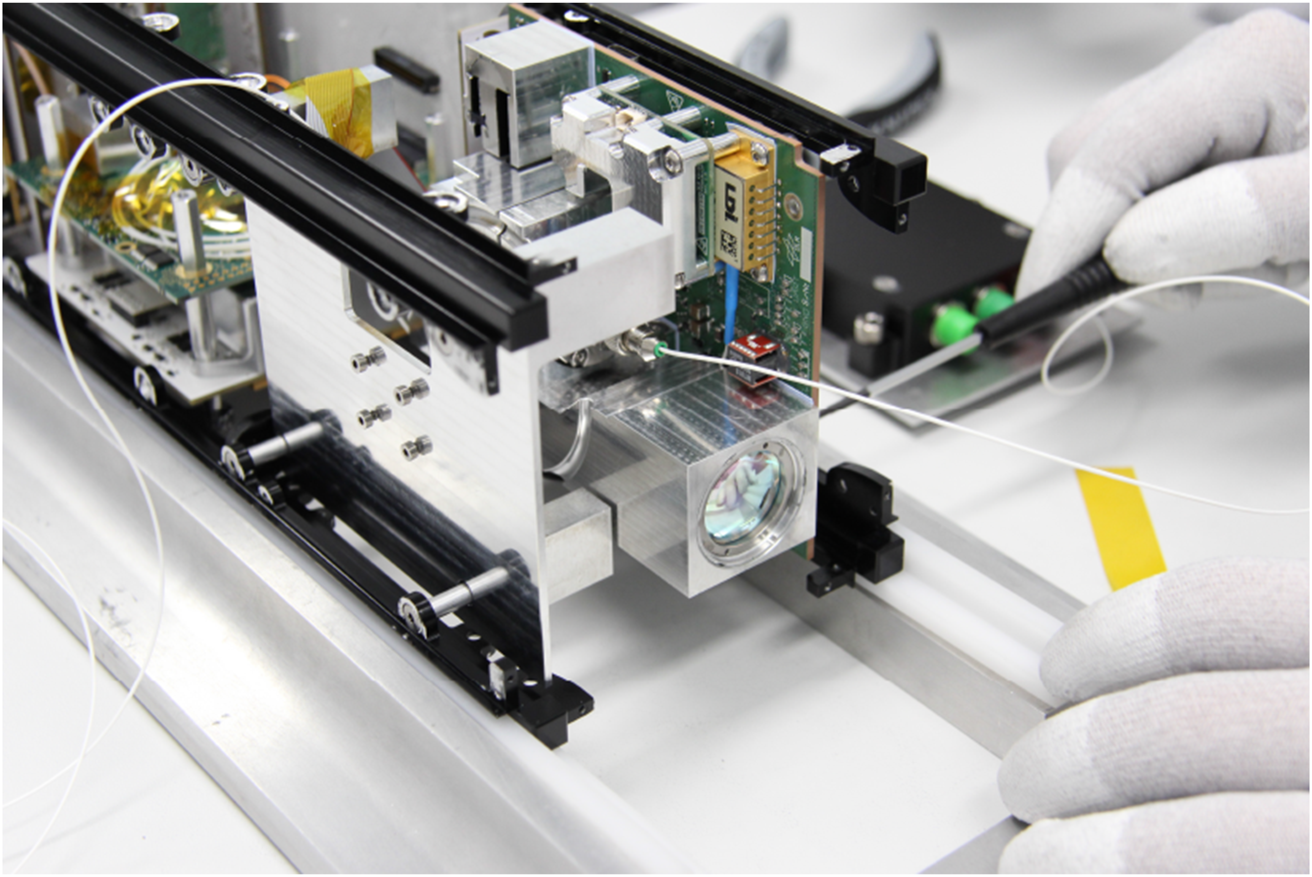
A mechanical alteration was required for the QCT in comparison to its predecessor mission (Menninger et al., 2021). O4Q not only has to support a C-band wavelength in the transmit path, but also L-band and 850 nm. As a consequence, the telescope had to be extended by 10 mm due to the new optic design. At the same time, the PCB was enlarged to 104 mm by 96 mm so that the optomechanics still adhere to the CubeSat’s mechanical structure.
The FPA in O4C and O4Q is equipped with an FSM as the actuator. The FSM serves to compensate for the residual pointing error of the satellite in relation to a laser beacon transmitted from the optical ground station (OGS). Given the size constraints, it was determined that a micro-electro-mechanical system (MEMS) based actuator would be the optimal technology for the FSM. The advantage of high compactness is offset by a limited mechanical stability. Measurements from the predecessor terminal O4C showed that the FSM is the most sensitive component in the payload with regard to vibrations. Due to the increased size compared to the previous mission, the mechanical stability of the O4Q terminal had to be studied to improve its resistance to shock and vibration.
2.3 Simulation model preparation
A simulation model was constructed for the purpose of analyzing the impact of design changes on the natural frequencies. This is based on the application of FEM in Ansys. The CAD model of O4Q was used as a baseline that was derived from the O4C design. The optomechanical design is firmly defined due to the requirements of a wavelength multiplexed system, it is therefore not possible to apply significant changes to it. In addition, the installation space in the satellite is limited, so that a preferred solution with external stiffening structures (Rödiger et al., 2023) is not an option. The simulation model consists of the two core elements, an FSM and the remaining optical terminal.
Since the FSM is a proprietary product from Mirrorcletech (Milanovic et al., 2004), no detailed simulation model is available. Therefore, a substitute model is proposed to represent the most important dynamics. The mirror itself is defined as a shell, while the spring effect was added with a connected beam model representation. While the dimensions of the mirror are known from the data sheet, the stiffness of the beam was tuned to match the resonance frequencies at approximately 330 Hz and 1500 Hz for this device type, A8L2.2-4600(AU). It should be noted that these values may vary within a specified tolerance. Figure 2(a) identifies the first natural frequency of the FSM model through a modal analysis as a tilting motion to be 330 Hz. The color map reflects the scaling of the eigenvectors in order to identify that resonance mode. This result was used to verify the representative model which can be adapted to the actual FSM device. Afterward the model was merged with the complete model depicted in Figure 2(b). It shows the prepared mesh model for modal and random vibration analysis and to perform the design trade-offs discussed in the next section. The MEMS FSM on its PCB showing (a) a 330 Hz natural frequency mode after modal analysis and (b) the final meshed model consisting of 500 thousand nodes.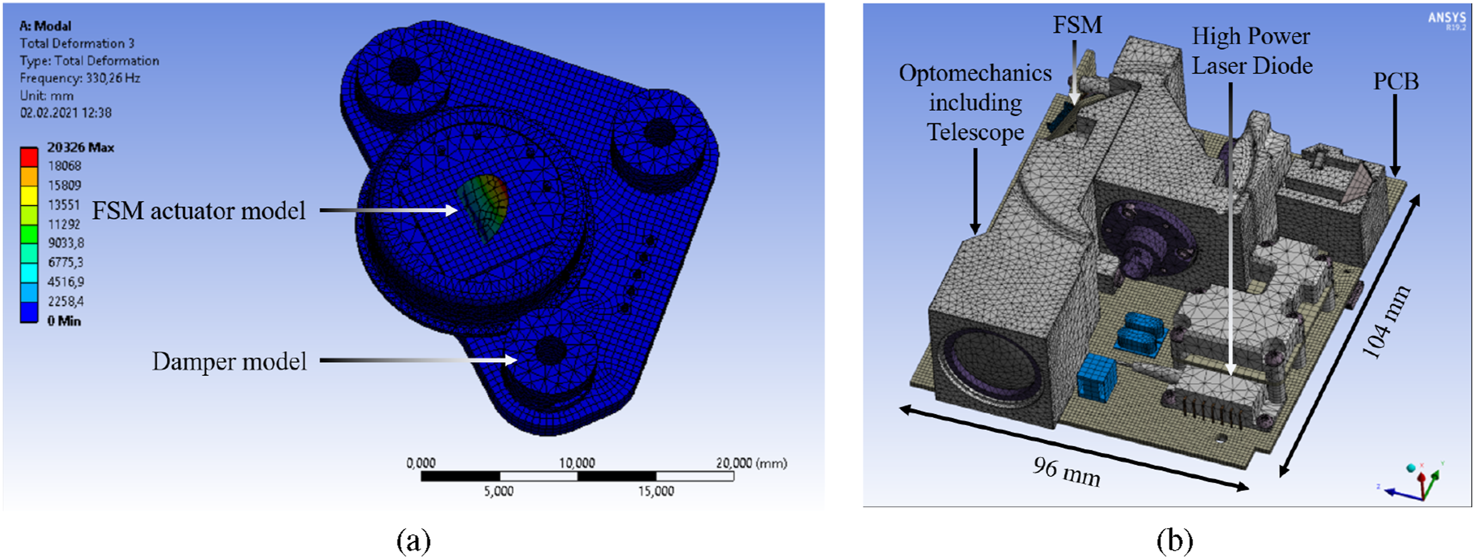
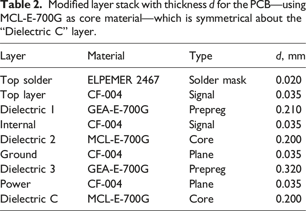
Since the CAD model contains detailed information, including the individual soldered components on the PCB, the FEM model was defeatured without removing any significant mass for the sake of saving simulation time. Furthermore, an investigation was conducted to ascertain whether a shell representation of the PCB’s layer stack as shown in Table 2 yielded identical outcomes as a solid model. As a consequence of the comparatively thin copper layers between the core materials, the same results were obtained in the test run. This resulted in a notable reduction in computing time while maintaining the same quality of results. In the case of meshed solid models, a minimum of two elements were employed throughout the thickness of the components.
2.4 Evaluation of the initial design
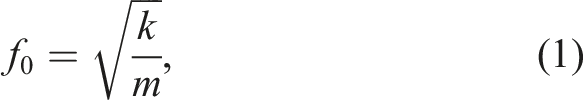
The evaluation starts with the initial design which combines the O4Q optomechanics and the initial PCB design derived from O4C. Preliminary simulations have confirmed the assumption that the natural frequencies of the overall system threaten to coincide with those of the FSM. The major influencing factors can be derived by simplified observation of a mass-spring-damper model. Its natural frequency is described by

2.4.1 Printed circuit board material and thickness
In order to prevent the excitation of the mirror resonance frequency by amplifying the input loads from the rocket through the transfer function of the QCT, it is necessary to ensure that both resonances of the FSM and QCT are well separated from each other. If possible, a safety factor of two is desirable. The requisite specifications can be fulfilled by either reducing the terminal mass or increasing the stiffness of the optical bench.
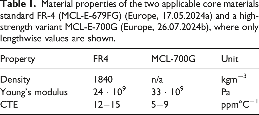
Various options for the combination of the core materials do exist. The ones investigated here are MCL-E-679FG, MCL-E-700G, copper-invar-copper (CIC), copper-molybdenum-copper (CMC), and aluminum. The trade-off is done in terms of Young’s modulus, coefficient of thermal expansion (CTE), and manufacturing complexity. The aluminum core material was not investigated in the FEM analysis due to the significant alterations to the manufacturing process necessitated by the resizing of vias and track widths, which would have prevented the allocation of sufficient space for all components and their interconnections. CIC as well as CMC are composite materials consisting of a core layer of invar or molybdenum and a top and base layer of copper for the wiring of the electrical components. Compared to MCL-E-679FG and MCL-E-700G, CIC and CMC show a higher Young’s modulus of 140 GPa and 269 GPa, respectively, while the CTE remains in the same order. Nevertheless, the manufacturing complexity is again more complex compared to FR-4.
Material properties of the two applicable core materials standard FR-4 (MCL-E-679FG) (Europe, 17.05.2024a) and a high-strength variant MCL-E-700G (Europe, 26.07.2024b), where only lengthwise values are shown.
Modified layer stack with thickness d for the PCB—using MCL-E-700G as core material—which is symmetrical about the “Dielectric C” layer.
2.4.2 Damper design considerations
A damper at the interface between FSM PCB and optomechanics was introduced. The company SMAC offers a range of standardized and adaptable damper options. The low-profile damper (part number: REF 101471) was adapted such that a low-pass behavior attenuates the critical frequencies. At the same time, however, it was chosen to be stiff enough to ensure that oscillation during take-off cannot lead to shock induced stress whenever the elongation length reaches the size of the gap between PCB mounting and the adjacent optomechanics. This was achieved through the proprietary material Smactane which reaches a Q factor of two. The dampers are designed to hold the PCB in a sandwich assembly as shown in Figure 3. Both dampers fit into the cavities of the PCB with their elastomeric side and are fixed in position with their molded washer, facing the pedestal stud on the bottom side. This way the PCB is mounted between both dampers, while they are slightly compressed by the screw. The mounting holes are manufactured with a tolerance of 0.05 mm of the radius. Another important aspect that is covered by the choice of material is a low outgassing behavior, since the optical components could otherwise suffer from accumulated particles, reducing the transmission of light through the system. FSM PCB assembly with the construction of the pedestal stud and the damper.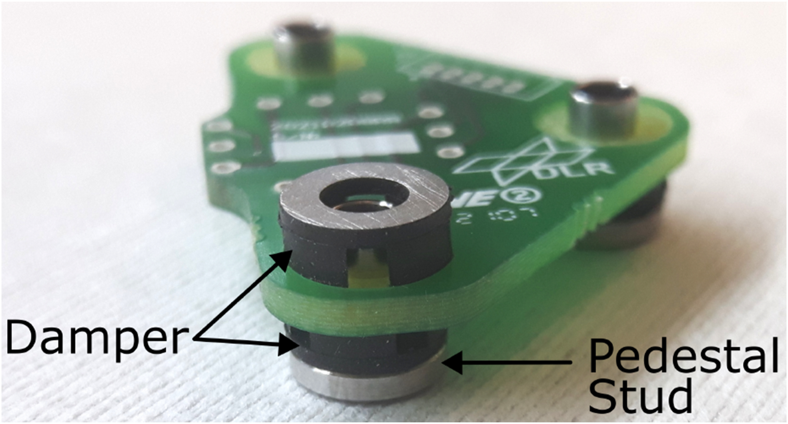
2.4.3 Optomechanic mounting interfaces
Based on the findings of the modal analysis, the loads, occurring on the QCT during take-off, are examined in a random vibration analysis. It is important that all stresses remain within the elastic yield strength of the materials. It prevents permanent plastic deformation that could affect the alignment of the optics or even lead to damage. Since the highest equivalent von Mises stress is expected at the attachment points of the optomechanics, these points were examined thoroughly. Due to the extended telescope, increased stress was induced into the PCB. In order to distribute the load more evenly, two additional attachment points were provided, resulting in the final drill pattern as depicted in Figure 4, showing attachment points for the satellite structure, the optomechanics and the high power laser diode transmitter sub-assembly (see Figure 2(b)). This measure has reduced the expected stress by 21.5% to 157 MPa at the maximum. PCB drill holes placement for mounting interfaces to satellite structure (blue), optomechanics (orange), high power laser diode assembly (green), and the introduced stress release mounts (red).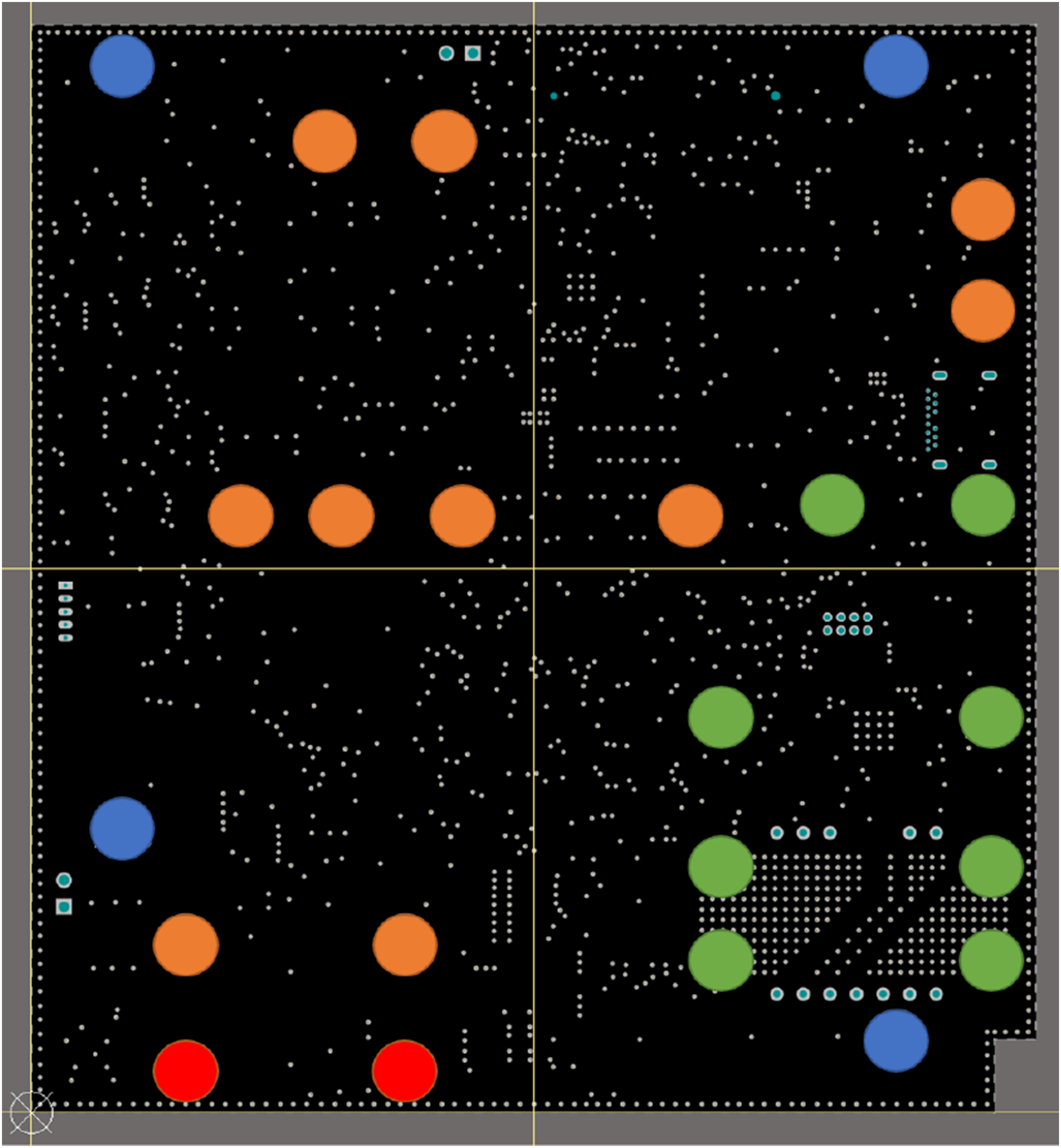
2.5 Modal analysis and random vibration response
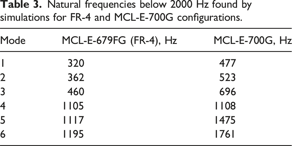
Natural frequencies below 2000 Hz found by simulations for FR-4 and MCL-E-700G configurations.
In a subsequent random vibration analysis, the identified natural frequencies were used to calculate the response at the FSM actuator, as seen in Figure 5, using the launch vibration spectrum provided by SpaceX for a Falcon 9 launch. The overall level yielded 7.5gRMS. Note that these are qualification levels, whereas the acceptance level, which was used in the final flight model satellite qualification, reduces the load down to 5.13gRMS. Additionally, the whole satellite was integrated in a dampened deployer and, therefore, even lower response levels can be expected for the launch of QUBE on the Transporter-11 vehicle. Comparing the random vibration spectrum (a) before and (b) after the design changes with a visible shift of the resonance peak and dampening of the dynamic response in the critical frequency bands marked in red.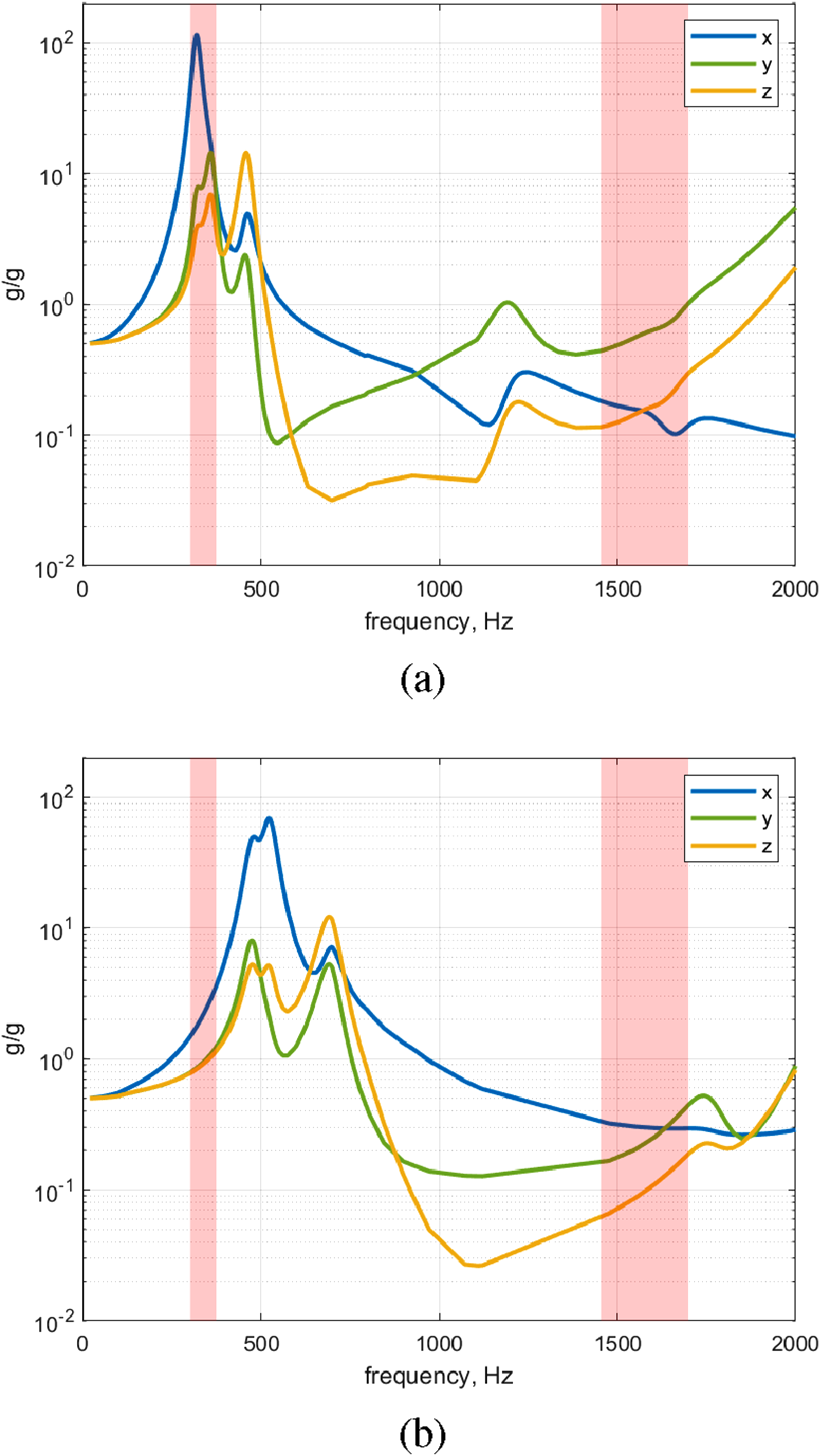
When comparing the MCL-E-679FG with the MCL-E-700G, it is clearly visible that the first natural frequency shifted. But additionally, the introduced damping flattened the response, such that the amplification dropped from 140 to 70 at the first peak. It is also evident that the second resonance frequency range of the FSM extends beyond the −3 dB frequency of the transfer function and is therefore well dampened.
Another aspect of random vibration loads is the induced stress on the mechanical parts, which must remain within structural limits. Therefore, an equivalent stress analysis was conducted and revealed a high 3σ level of about 200 MPa for the given vibration scenario of a Falcon 9 launch. That is already close to the yield strength of the metal structure and could even lead to severe damage on the PCB material. An effective way to reduce stress is to distribute the load. As the telescope grew in size, it became feasible to incorporate two supplementary mounting points within the telescope aperture housing, where the maximum stress was observed. This countermeasure reduces the maximum stress to 157 MPa which is a decrease of 21.5% and below the yield strength of aluminum 6061-T6 of 275 MPa and well within the ultimate tensile strength of 310 MPa.
To gain a more comprehensive understanding of the region of interest, where the highest stress was identified, a more detailed examination was necessary. The result shows that the peak stress exist on the washer belonging to the terminal screws. The purpose of the washer is to provide an increased surface area for the distribution of punctual loads, thereby reducing the load on the PCB. The resulting stress acting at the PCB itself is at 49.7 MPa which is within the ultimate tensile strength of standard FR-4 and therefore also true for MCL-E-700G.
3. Hardware compliance validation
The simulation is based on necessary assumptions and reasonable simplifications concerning the exact properties of the materials and the influence of the bonded and bolted mechanics. Therefore, a validation on a vibration test system (shaker) was planned based on the qualification concept (Rödiger et al., 2023). The intention was as well to validate the simulation approach which is then being reused for subsequent missions. Another part of the validation tests was an acquisition and tracking procedure test with spinning reaction wheels, which emit micro-vibrations during operation. Results of both tests will be presented in the following where the first and second natural frequencies of the assembled FSM device are 349 Hz and 1550 Hz, respectively. As previously indicated, the precise resonance frequency differs among devices due to variations in the manufacturing process. Therefore, an improvement to the simulation is expected by substituting the 330 Hz baseline with the actual eigenfrequency.
3.1 Validation through shaker measurements
The validation test with the shaker was done on payload level. A test on payload level excludes dampening effects by the satellite structure or the transfer function of the dispenser. This allows to analyze the effects of the measures described above isolated from the final environmental mechanics. Figure 6 shows O4Q installed on the shaker. The payload was tested according to the ECSS standard for environmental testing (ESA, 31.05.2022). This includes a modal analysis before and after every test and a sine and a random vibration test in all three axes. This results in a total of 15 tests, with the order of the tests being modal-sine-modal-random-modal for the x-, y-, and z-axis. The resonance search test for the qualification of the payload was successful, as defined by the ECSS standard, since the first natural frequency was at 446 Hz and did not change by more than 5%, while the amplitude changes stayed below 10% throughout the tests. O4Q shaker test setup with the engineering and qualification model.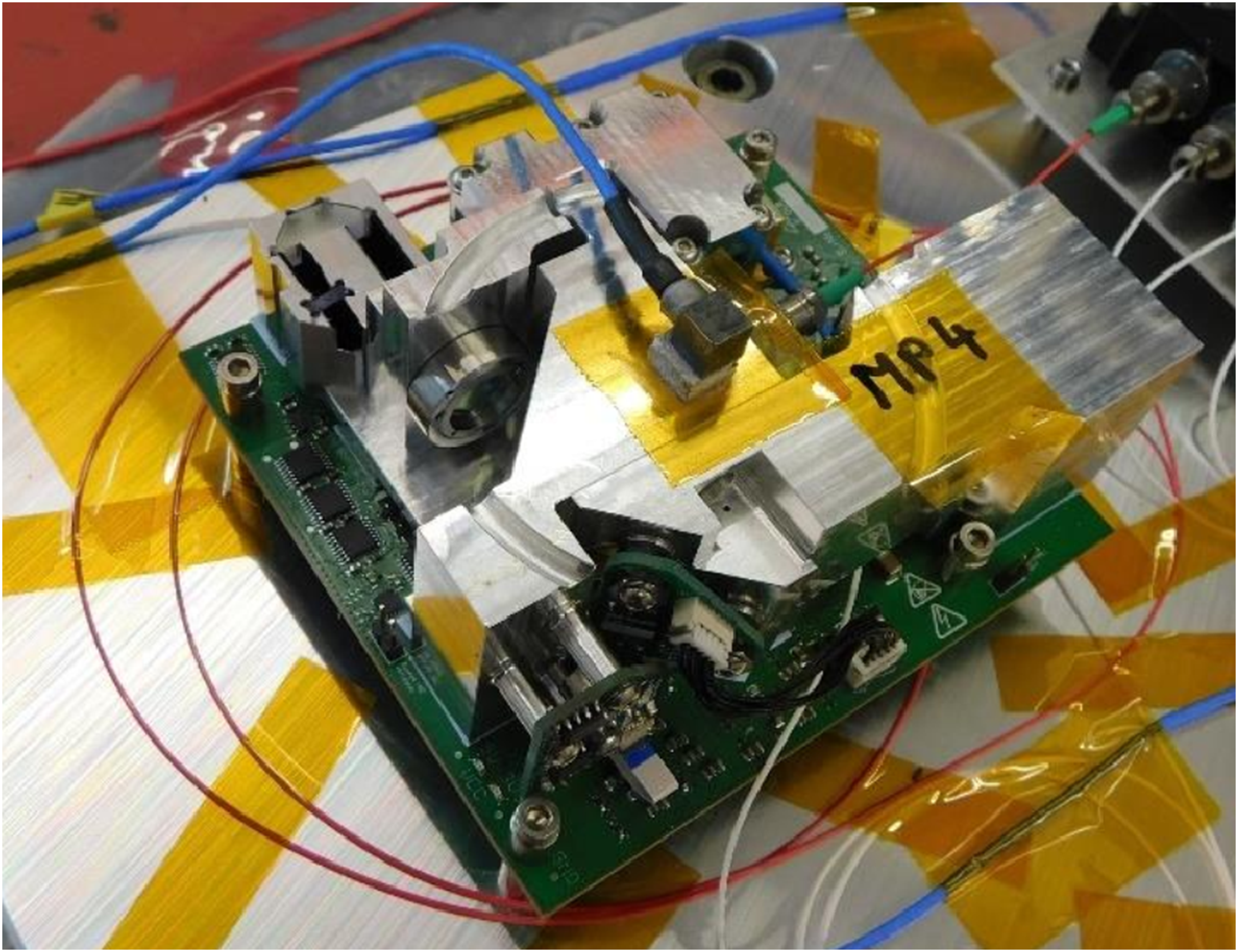
Comparison of natural frequencies below 2000 Hz found by simulation and the resonance search executed between 5 and 2000 Hz with 0.5 g and 2 octaves per minute.
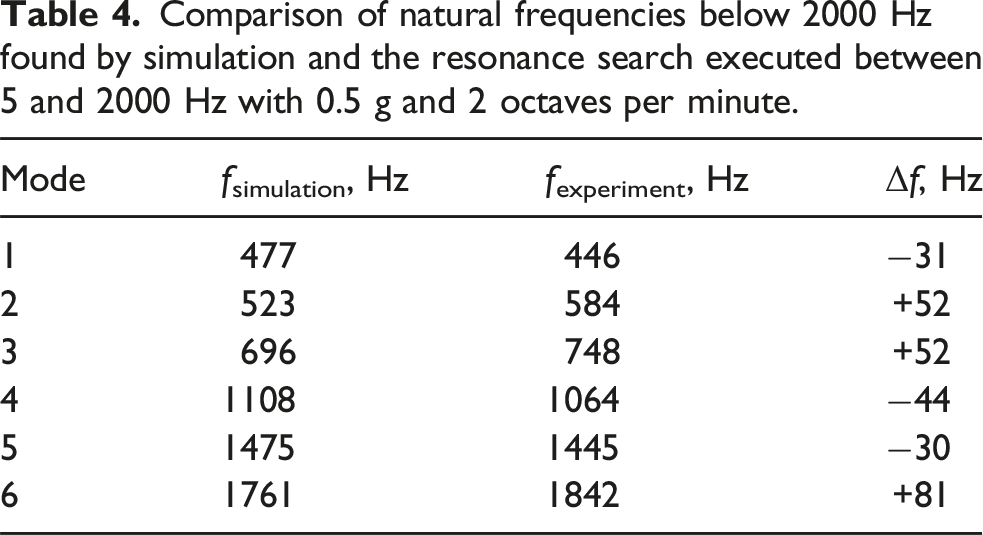
Given the aforementioned simplifications made to the model, deviations are to be expected. The reduction in components leads to a decrease in mass and an increase in stiffness compared to realistic bolted connections. It is evident that both of these factors result in an overestimation of the first resonance frequency. However, the deviation of 31 Hz for the critical first eigenfrequency of the optomechanics is acceptable because the primary focus of this study was the relative improvement.
On another note, the vibration response spectrum was analyzed using the shaker measurements. Note that the sensor position indicated in Figure 6 is not at the FSM PCB position, since doing so would significantly alter the local mass. Therefore, response curves between measurement and simulation are not expected to be perfectly identical. When comparing the results to Figure 5, the first peak at the resonance frequency shows an amplification of 20, rather than the 70 identified in the simulation. This indicates that the damping was underestimated in the simulation, which again leads to an overestimation of the first eigenfrequency compared to the experiment.
A final flight acceptance test was carried out with the fully integrated satellite flight model. All parameters were nominal and the procedure for a downlink showed a scanning spiral which verified that the FSM had also survived the final ground test.
3.2 Micro-vibration impact analysis
In addition to the considerable loads experienced during launch, which must be withstood when the satellite is deactivated, there are also vibrations present within the satellite during its operational phase. These micro-vibrations are predominantly generated by the attitude control system, particularly by the reaction wheels. The reaction wheels generate angular momentum through the combination of moment of inertia and rotational speed, which also acts on the satellite in accordance with the law of conservation of momentum. The rotational speed, which is measured in revolutions per minute (RPM), can then be used to derive an oscillation frequency in Hertz. The harmonic, superimposed frequencies of higher orders are determined as an integer multiple N. For the FSM under consideration, the critical RPM setpoints are (a) O4Q validation with (1) beacon laser, (2) waveform generator for transmit clock signal, (3) beacon laser fiber input, (4) power-meter, (5) O4Q, (6) QUBE satellite, and (7) camera for transmit signal observation and (b) microvibration analysis integrated in the satellite with running reaction wheels.
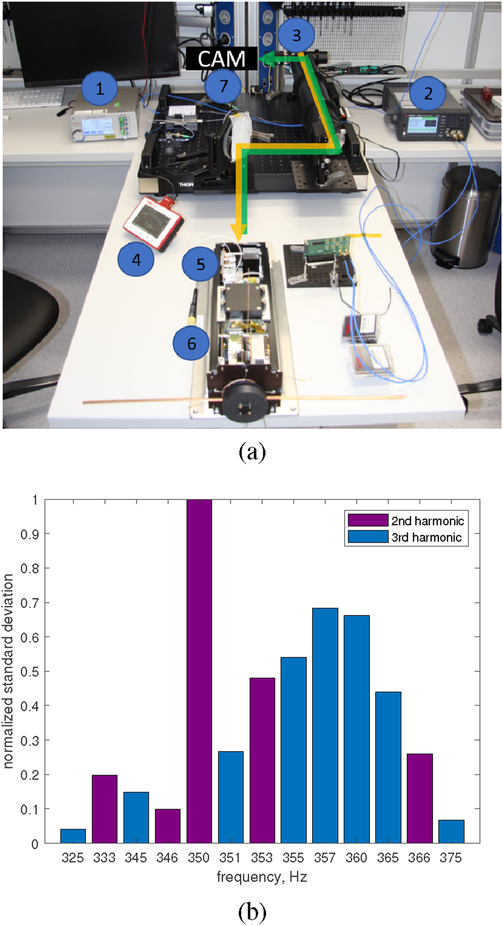
In order to align and test the tracking system in a laboratory setting, a dedicated optical ground support equipment is employed (see Figure 7). The system is based on an optical system comprising a fiber collimator, beam splitter, afocal telescope, and a camera. A beacon laser is connected to the fiber collimator, and the laser beam is transmitted through the beam splitter. Subsequently, the telescope expands the beam (orange) to exceed the terminal aperture. This emulates a laser beacon transmitted from an OGS and can be used to test the tracking system. The laser transmitter of the terminal can enter the telescope and is reflected by the beam splitter toward the camera (green). In this configuration, the terminal tracks the beacon signal while the camera monitors the transmitter laser beam.
During operation, a downlink procedure with acquisition and tracking was started. The link was established and maintained. However, it could be seen that the closed-loop tracking error shows a higher standard deviation when the satellite is operating in the critical speed range. A test was carried out over 20 minutes at the worst-case operating point of 10500 min−1. It resulted in a maximum 3σ tracking error of 72μ rad which is well within the approximated full width half maximum divergence of both 1550 nm with 118μ rad and 850 nm with 95μ rad and can therefore fulfill the pointing requirement of −3 dB or less.
After evaluating the launch vibration qualification and the microvibration tests, both could be closed with a success. O4Q was launched into orbit on the 16th of August 2024 (Vandenberg, USA) by a Falcon 9 rocket. Contact with the satellite was established, and after the subsystems were checked out, the first successful tracking results validated the functionality of the QCT (Rödiger et al., 2025). Therefore, there is sufficient evidence to support the conclusion that the improvements and testing efforts of this study yielded the expected results.
4. Summary and conclusion
The primary objective of this structural analysis is to modify an existing system in a manner that allows for the survival of a rocket launch without damage, while simultaneously meeting the pointing requirement under the influence of micro-vibrations. Specific consideration is given to the FSM, which is vulnerable to vibrations due to its optimized size and delicate construction. A representative simulation is employed to assess the efficacy of design alternatives. This assertion has been validated by a vibration test system. As a mean of enhancing the structural integrity of the PCB, the use of the robust MCL-E-700G material has been incorporated into the design, thereby augmenting the strength of the PCB employed as an optical bench and consequently shifting the critical natural frequencies into the desired range. The choice was a trade-off between the available envelope and the structural requirements. Although the design change is sufficient, materials with an even higher modulus of elasticity have been identified for a potential future mission launch vehicle with higher expected loads. Moreover, a damper is mounted between the FSM board and the optomechanics with the objective of further suppressing critical vibrations. Finally, two additional holes are drilled in the telescope to reduce stress in this location to a minimum. Both the payload qualification test and the acceptance test of the flight model in the satellite were successfully completed. As a result, the margin between the critical resonance frequencies was increased by 1.28 which will allow the payload to survive launch. Further, the structural integrity will be kept due to a decrease of 21.5% of maximum mechanical stress during launch. Finally, the acquisition and tracking behavior was validated in the installed satellite achieving 72μ rad of pointing error, faced with worst-case micro-vibration conditions, which is still within the divergence of the system and therefore gives enough margin for in-orbit operation.
Footnotes
Acknowledgments
The authors would like to thank the consortium of Zentrum für Telematik, Ludwig Maximilian Universität München, and Max Planck Institute for the Science of Light for the excellent cooperation in the QUBE project.
Funding
The authors disclosed receipt of the following financial support for the research, authorship, and/or publication of this article: The project on which this report is based was funded by the Federal Ministry of Research, Technology and Space under the funding code 16KIS0767. The authors are responsible for the content of this publication.
Declaration of conflicting interests
The authors declared no potential conflicts of interest with respect to the research, authorship, and/or publication of this article.
Data availability statement
The data that support the findings of this study are available from the corresponding author upon reasonable request.