
Abstract
It is generally accepted that semi-actively (S/A) controlled dampers can significantly improve the behaviour of a road or rail vehicle. In the case of a railway vehicle, it is possible to increase comfort using S/A control of vertical or lateral secondary dampers. On another way, S/A control offers the possibility of solving a contradiction in the damping requirements for different driving modes, in the case of control of bogie yaw dampers. However, this case has not yet been sufficiently investigated. This paper deals with applying magnetorheological dampers with semi-active control in the locomotive bogie to reduce hunting oscillation. The magnetorheological bogie yaw damper design, new algorithms for its control and application on a complex multi-body locomotive model that simulates fast running on a real straight track are shown. An essential part of the paper focuses on the effect of the damping force level and damper force transient response time. The results have shown that using the semi-active control of the yaw dampers makes it possible to reduce vehicle body lateral oscillation by 60% and improve running stability for higher equivalent conicity and subcritical speed. The critical speed can be increased by more than 250 km/h. The efficiency of the proposed semi-active control increases with increasing damping force level and decreasing transient response time. The control is most effective under conditions of low equivalent conicity.
1. Introduction
Currently, the importance of high-speed railways is increasing worldwide. As the speed of the trains increases, various problems appear that need to be solved. One of the biggest problems is the contradiction in the requirements for the vehicle running stability at high speeds on a straight track and for the minimisation of the lateral force effects of the vehicle on the track in small radius curves as well as in the diverging branch of switches. In the first case, the high stiffness of the wheelset guiding in the bogie frame and the high bogie yaw stiffness are desirable to ensure high stability. In the latter case, these requirements are exactly the opposite. Because yaw dampers directly affect the torque on the rotation of the bogie, these dampers are subject to conflicting requirements that are difficult to solve with conventional passive dampers.
An alternative to passive suspension is active or semi-active suspension. The active system contains actuators instead of springs and dampers (Diana et al., 2002). However, these systems are relatively complex, expensive, and energy-intensive and pose difficulties when implementing a fail-safe system (Goodall, 2011). A simpler alternative is a semi-active damping system, where it is possible to change the damping characteristics of the damper in the required way based on input data from various sensors (Shin et al., 2012; Spelta et al., 2012). In the case of a magnetorheological (MR) damper, the fail-safe system can be provided using a permanent magnet (Jeniš et al., 2021). Several research teams use S/A dampers in secondary suspension in the lateral direction (perpendicular to the direction of travel) (Codecà et al., 2007; Hudha et al., 2011; Jeniš et al., 2023; Shin et al., 2012; Shin et al., 2014; Sun et al., 2013; Wei et al., 2016), (Wang and Liao, 2009a), (Wang and Liao, 2009b). The reason is the significant reduction of the vehicle body oscillation.
The vehicle running stability could be increased at the level of the wheelset guidance by suitable active (Mei et al., 2002; Shen and Goodall, 1997) or semi-active (Fotouhi and Yousefi-koma, 2006; Wei et al., 2016) elements. However, directly applying controlled damping elements at this location would mean a significant intervention in the vehicle structure.
The second way to solve the problem of different damping requirements for different driving modes is a semi-active (S/A) or active yaw damping system. Replacing the passive yaw damper with an actively or semi-actively controlled element does not involve major intervention in the running gear structure (Braghin et al., 2006). The active system helps the bogie turn in the desired direction, that is, into the curve (Diana et al., 2002).
However, S/A control of the bogie yaw damper has not yet been sufficiently investigated. Only Wang et al. (2021) simulated the effect of a hydraulic semi-active yaw damper on an increase in critical speed.
The time of damper transient response and damper dynamic force range are crucial for the semi-active control efficiency (Macháček et al., 2019).
1.1. Problem formulation
The possibilities of MR bogie yaw damper control have not yet been explored. Besides, it is known that the response time of a damper has a crucial effect on the effectiveness of S/A control, but it is not known what response time is short enough for a yaw damper. Generally, the S/A controlled dampers perform better with higher forces than the ideal forces for a passive damper (Strecker et al., 2015a). However, the ideal damping force for a S/A-controlled MR yaw damper is unknown. It is also known that vehicle stability is greatly affected by wheel-rail contact conditions (Polách, 2010), but it is not known how S/A control efficiency is affected by different contact conditions.
This paper presents the influence of new algorithms for the S/A control of MR bogie yaw damper on vehicle running stability (lateral axle box force), vehicle body lateral acceleration and critical speed. Simulations are performed for different wheel-rail contact conditions, damping force levels and damper transient response times.
The MR damper force model was created according to a real MR bogie yaw damper for a railway vehicle, including the measured real damper transient response and dynamic force range.
2. Materials and methods
Figure 1 shows the control schema. Further chapters describe the semi-active control design, vehicle and MR damper models. Control schema.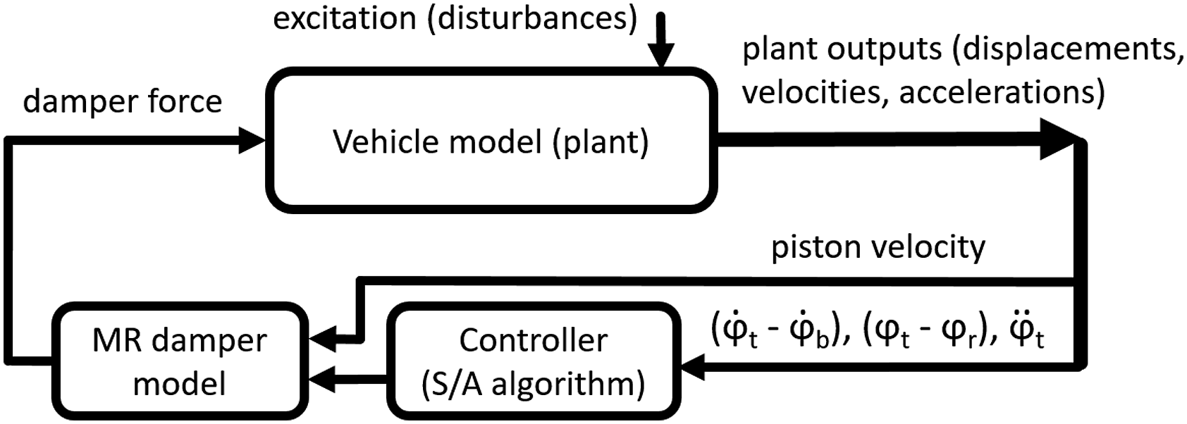
2.1. Semi-active control design
In the paper, two semi-active algorithms were designed to control the MR bogie yaw dampers. Both aim to increase vehicle running stability and reduce lateral vehicle body vibration.
The first algorithm (‘Tracking’) maintains a zero angle between the bogie and track axes. The second (‘Accelerating’) is based on the Modified Groundhook algorithm (Strecker et al., 2015a) and tries to minimise the oscillation of lateral forces in the wheel-rail contact. The results of these two algorithms are compared with the so-called Full-on-state mode. The damper is still fully activated in this mode and behaves like a standard passive damper.
2.1.1. Tracking algorithm
The idea of the algorithm Tracking is to keep the bogie angle to the track axis Angles diagram.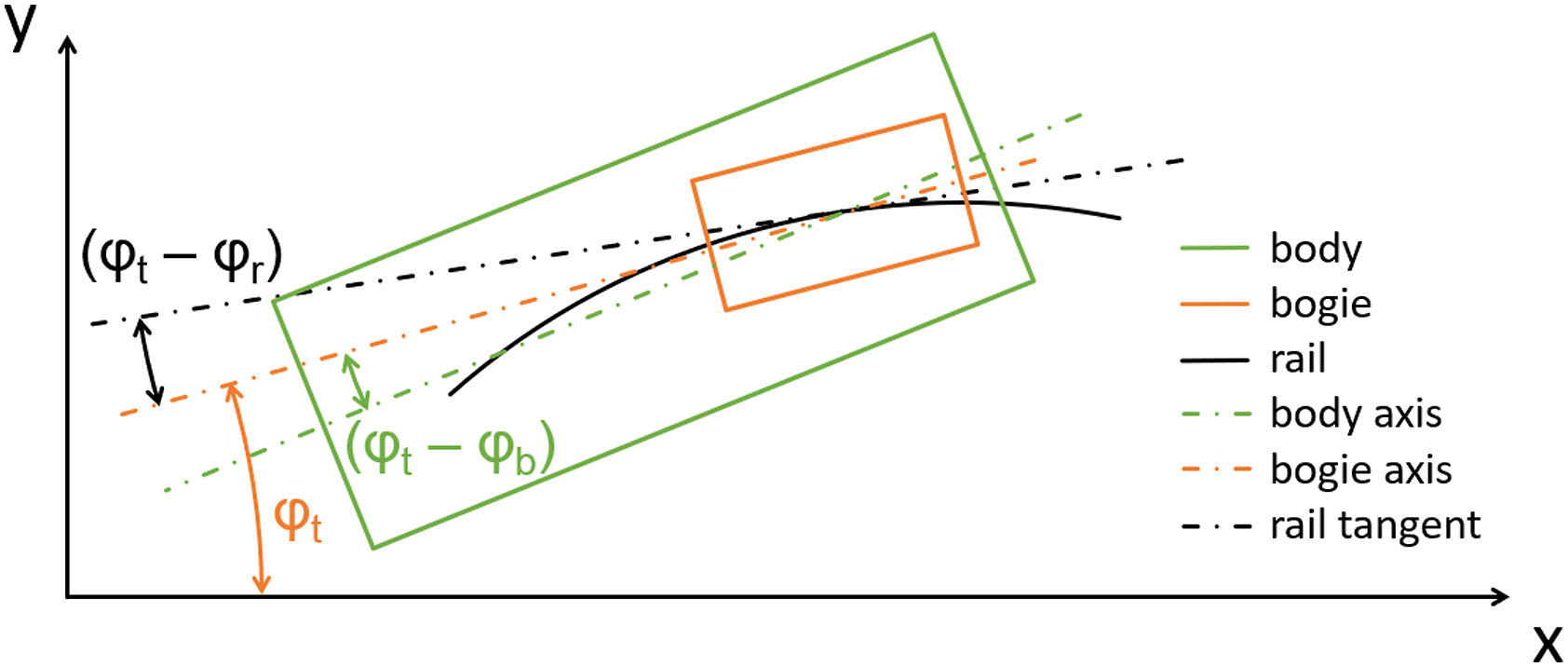
The algorithm assumes a perfect prediction of the track axis position to determine the actual value of the angle
2.1.2. Accelerating algorithm
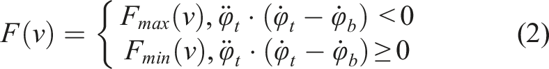
A second algorithm was designed to control the bogie for the case where the track axis position is unknown. This algorithm works with bogie angular acceleration (an easily measurable variable). This algorithm is derived from the automotive Modified Groundhook algorithm, which aims to minimise the oscillation of vertical forces in wheel-road contact. The Groundhook algorithm function was verified on a real car suspension model (Žáček et al., 2022). In this research, the algorithm was modified to minimise the oscillation of lateral forces in the wheel-rail contact. If the bogie is angularly accelerating, the damper is deactivated, and on the contrary, if the bogie is angularly decelerating, the damper is activated. Again, this only applies if the vehicle body angular velocity is less than the bogie angular velocity. If the body angular velocity exceeds the bogie angular velocity, the damper demand will be the opposite again. Mathematically:
In the simulations in this research, the input variables to the algorithms were not filtered. However, in the experimental verification of the Modified Groundhook algorithm (Žáček et al., 2022), a low pass of 256 Hz was used (analogue filter of the sensor), and the delay caused by filtering had a negligible effect on the algorithm’s performance.
2.2. Vehicle model
The SJKV system (Czech abbreviation for ‘Simulation of a Rail Vehicle Run’) was used for simulations. It is a custom multi-body simulation software used to study the dynamic properties of railway vehicles.
The used vehicle model represents a modern four-axle electric locomotive with bolsterless bogies and a fully suspended asynchronous traction drive. The wheelset guiding and primary suspension consists of a longitudinal rod and two short coil springs per axle box (see Figure 4); the secondary suspension stage is created by a pair of flexi-coil springs on each side of the bogie. A lemniscate mechanism realises longitudinal force transmission between the bogie frame and vehicle body. Vertical and lateral secondary suspension and the primary suspension stage in a vertical direction are supplemented with hydraulic dampers; the bogies are fitted with longitudinal yaw dampers.
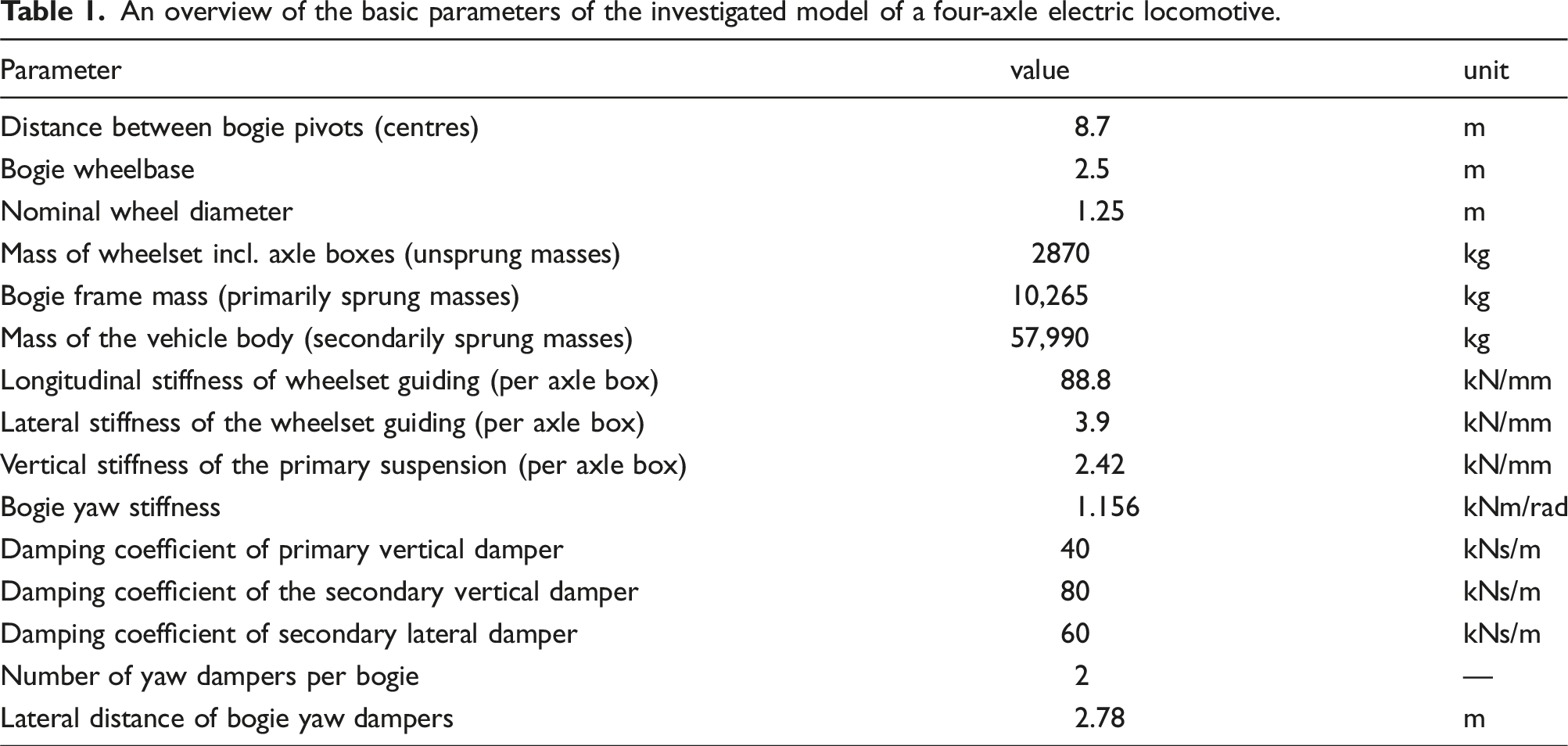
The locomotive model consists of fifteen rigid bodies (four wheelsets, eight axle boxes, two bogie frames including traction motors, and a vehicle body) with a total of 58 degrees of freedom (DoF), mutually connected by relevant flexible and damping joints. Each wheelset, bogie frame and vehicle body show six DoFs; the bodies representing individual axle boxes are modelled with two DoFs (lateral displacement relative to the wheelset axle and rotation around the axle). The mass of electric traction motors, including fully suspended gearboxes, is considered a part of the body representing the bogie frame, and the mass of the torque transmission device (hollow shaft with joint coupling) is split between the relevant wheelsets and bogie frames. There are eight more bodies in the system representing rails. These are joined with the inertial frame via elastic and damping couplings, and their position is defined by track alignment and irregularities.
An overview of the basic parameters of the investigated model of a four-axle electric locomotive.
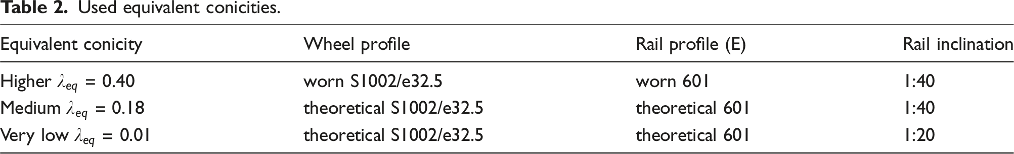
2.3. Wheel-rail contact conditions
Used equivalent conicities.
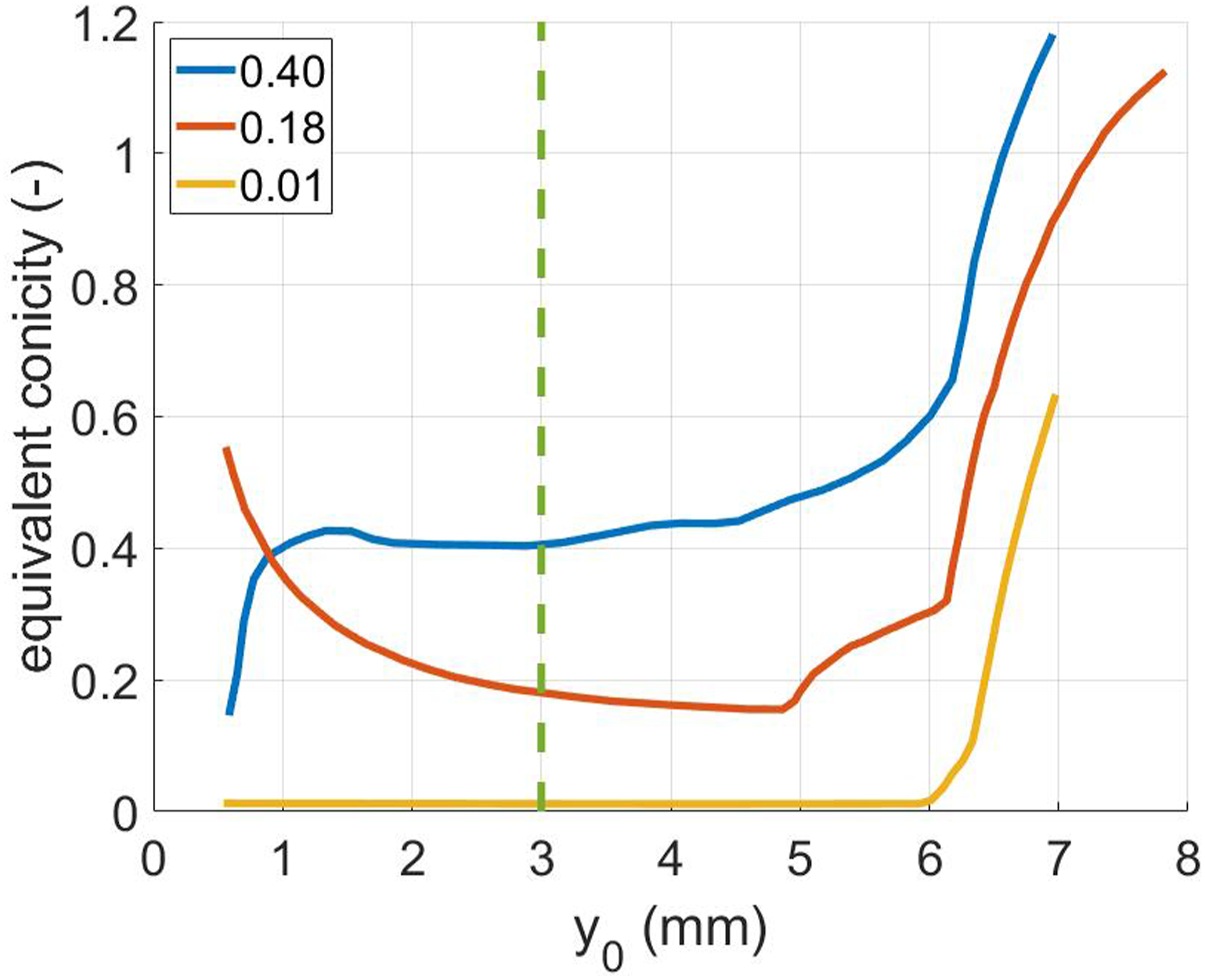
Considered equivalent conicity functions.
2.4. MR damper and its model
The key part of the semi-active suspension is a magnetorheological yaw damper designed for the bogie of a modern four-axle locomotive with a total weight of 90 t (Figure 4). The construction and parameters of the damper are described in detail in Kubík et al. (2021). The short transient response time is ensured by slots cut in the piston, which limit the eddy current (Strecker et al., 2019b). The damper’s maximum damping force equals the maximum damping force of a conventional bogie yaw damper. The key characteristics of the damper (force-velocity-current map and time of transient response) were measured. Prototype of yaw MR damper.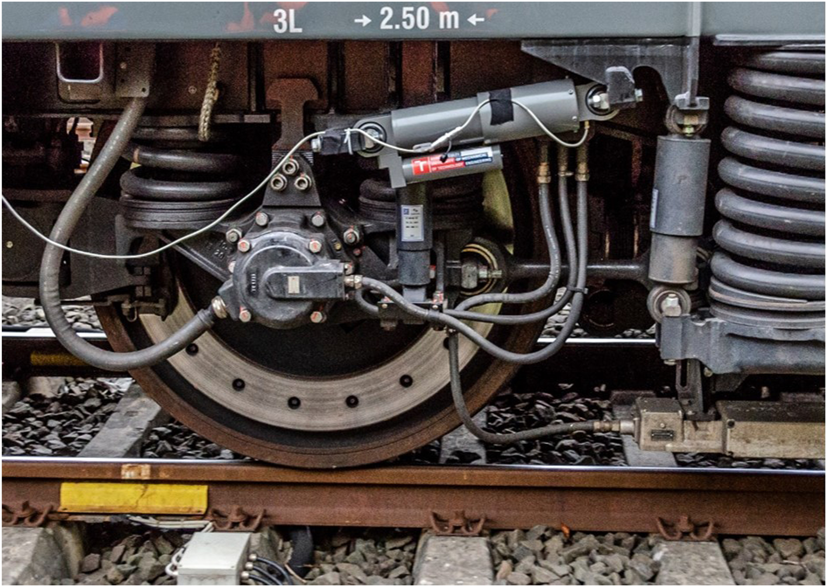
2.4.1. F-v-I map
The F-v-I (force-velocity-electric current) map expresses the dependence of the damper force on the actual piston velocity and the electric current in the coil. With the proposed control strategies, the damper operates in the so-called ON/OFF mode, that is, it switches between maximum and minimum damping forces (currents 0 A and 1.4 A).
The measured F-v curves and their simplification for simulation purposes are shown in Figure 5. The damper F-v curves are symmetrical for rebound and compression, whereas Figure 5 shows only the positive part of the F-v curves. The measuring methodology is described in detail in Strecker et al. (2015b). Measured (dotted lines) and approximated (solid lines) F-v curves of the MR damper for maximal and minimal current values (damper force level of 100% – nominal damping forces).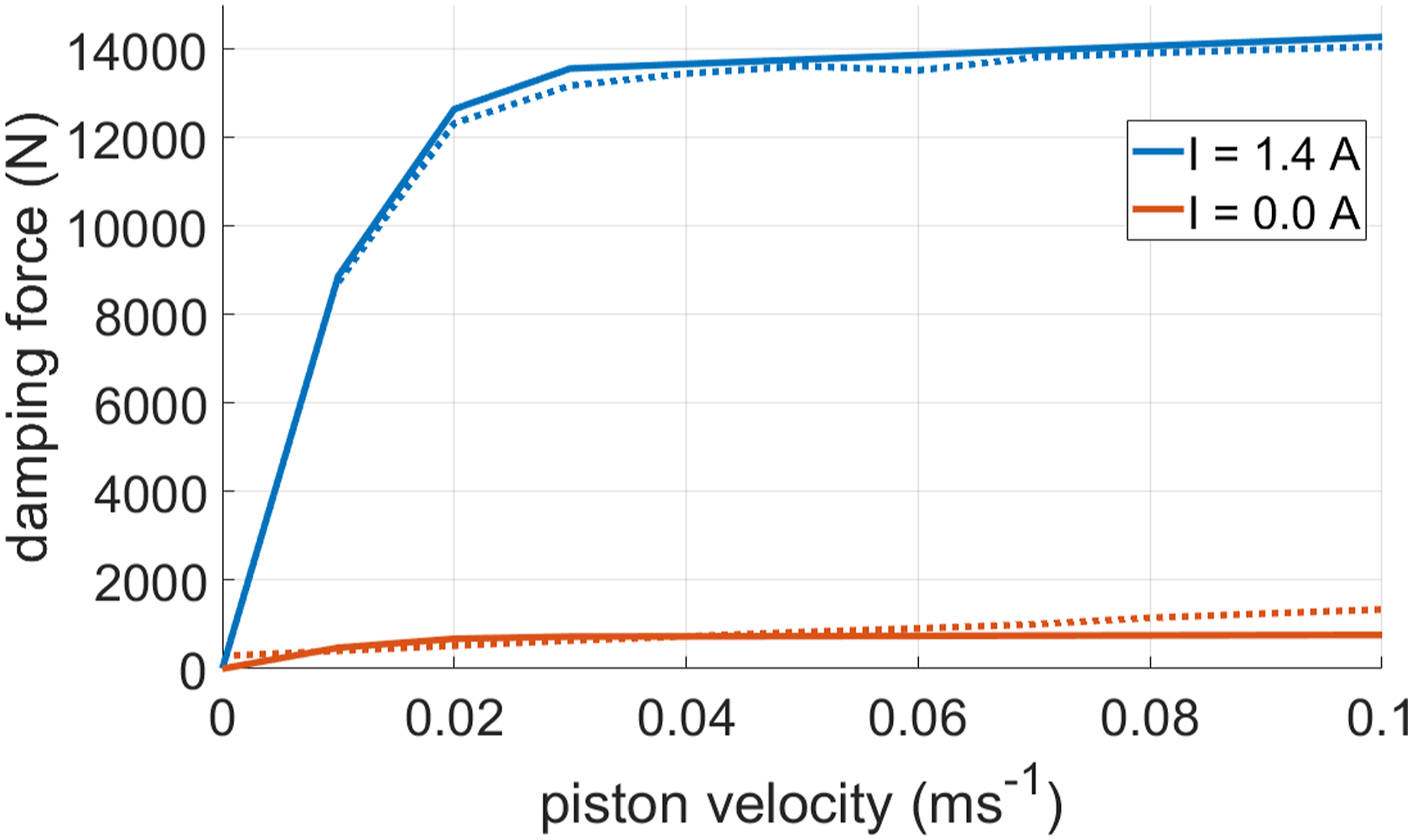
The damping force is small in small piston velocity in ON mode. It is due to the damper design – the piston is not sealed. At low piston velocities, a significant part of MR fluid flows around the piston (in the small gap around the piston). Therefore, the initial slope of the F-v dependency is due to the hydraulic resistance of the mentioned gap.
2.4.2. Damper transient response
For a real damper, there is a delay between the change of electric current and damping force. With a step change in the current, the damping force to the desired value increases or decreases exponentially (Figure 6). Therefore, the transition between the F-v curves in time is modelled in the simulation program as in a first-order dynamic system (Goncalves et al., 2003), using the equation of exponential function (3): Damper transient behaviour.
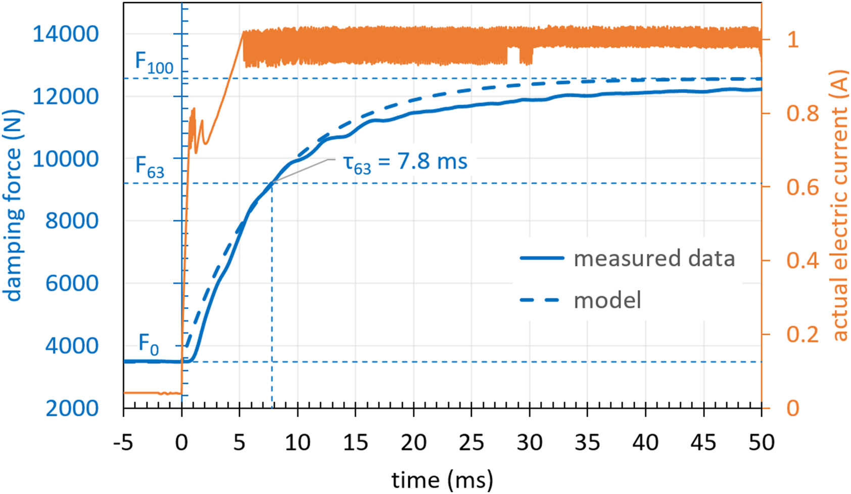
The damper time constant
For simplicity, the time constant for the drop is considered to be the same,
2.5. Plan of simulations and evaluation method
Two types of simulations were performed: (1) simulation of running on a track with measured irregularities to determine vehicle behaviour at subcritical speed and (2) theoretical stability analysis to determine the theoretical critical speed.
2.5.1. Simulation of running on track with irregularities
According to experience (Strecker et al., 2015c), the semi-active algorithm is assumed to work best with a damper force in the activated state that corresponds to at least 1.5 times the force of the ideal passive damper. Therefore, the influence of the F-v-I map scale on the control efficiency of algorithms Tracking and Accelerating and Full-on-state mode (constant maximum current 1.4 A) is investigated in this paper. Simulations were performed with a damper model of 100, 150, 200, 300 and 500% of the nominal F-v curves. This variable is referred to as the ‘damper force level’.
The influence of the MR damper transient behaviour is also investigated. Two cases were performed:
These cases were studied for 3 different wheel-rail contact conditions: low (
In all cases, it was simulated running on a real straight track (i.e. on a railway track with measured deviations of the rails from their ideal position) at 220 km/h, which was selected as the maximum test speed of the vehicle with the maximum speed of 200 km/h with respect to the requirements of the EN 14363 (CEN, 2020) (a requirement on the increase of the maximum speed of the vehicle by 10% during the tests).
Railway vehicle dynamic behaviour was evaluated using two parameters: (1) lateral axle box force
The lateral axle box force
For these quantities, a moving RMS with a window length of 100 m was evaluated (in the sense of evaluating vehicle running stability in accordance with the requirements of standard EN 14363 (CEN, 2020) for vehicle running tests). See Figure 8. Lateral axle box force was evaluated on all wheelsets, with the worst case always used for comparison.
2.5.2. Theoretical stability
The effect of semi-active control of the yaw dampers on the theoretical critical speed, that is, the critical speed on a straight track without irregularities, was also studied. In this case, the vehicle model was excited by the track’s lateral unevenness with an amplitude of 8 mm at an initial speed of 500 km/h and subsequently decelerated −1 m·s−2 to a speed of 50 km/h. In the simulation on the ideal track without irregularities, lateral movement of all wheelsets was observed. The speed at which the lateral oscillations disappear is called the critical speed for the specified conditions. More information on ways to investigate the critical speed of a rail vehicle can be found in Polách (2006) and Zelenka et al. (2013).
3. Results and discussion
3.1. Simulation of running on track with irregularities
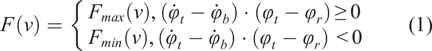
The time behaviour of the selected quantities in Figure 7 (top) demonstrates the function of the damper controlled by the Tracking algorithm. It is evident that the damper state changes when the bogie yaw angle reaches a local extreme value (the yaw angular velocity is zero) or a zero value. This observation corresponds to the definition of the algorithm (see equation (1)). In Figure 7 (bottom), which corresponds to the Accelerating algorithm, it can be seen that the most significant peaks of the damping force are reached in the areas where the angle between the bogie axis and the body axis increases, as in Tracking algorithm case. This fact fully corresponds to the requirement of damping the bogie yaw motion. The Tracking algorithm changes the damper state twenty times per second and the Accelerating thirty times, so it can be assumed that the Accelerating will depend more on the time of damper transient response. Detail of a part of the course of the front bogie angle to the vehicle body, the damping force of the right front bogie yaw damper and state of control algorithm (ON/OFF) under conditions of equivalent conicity 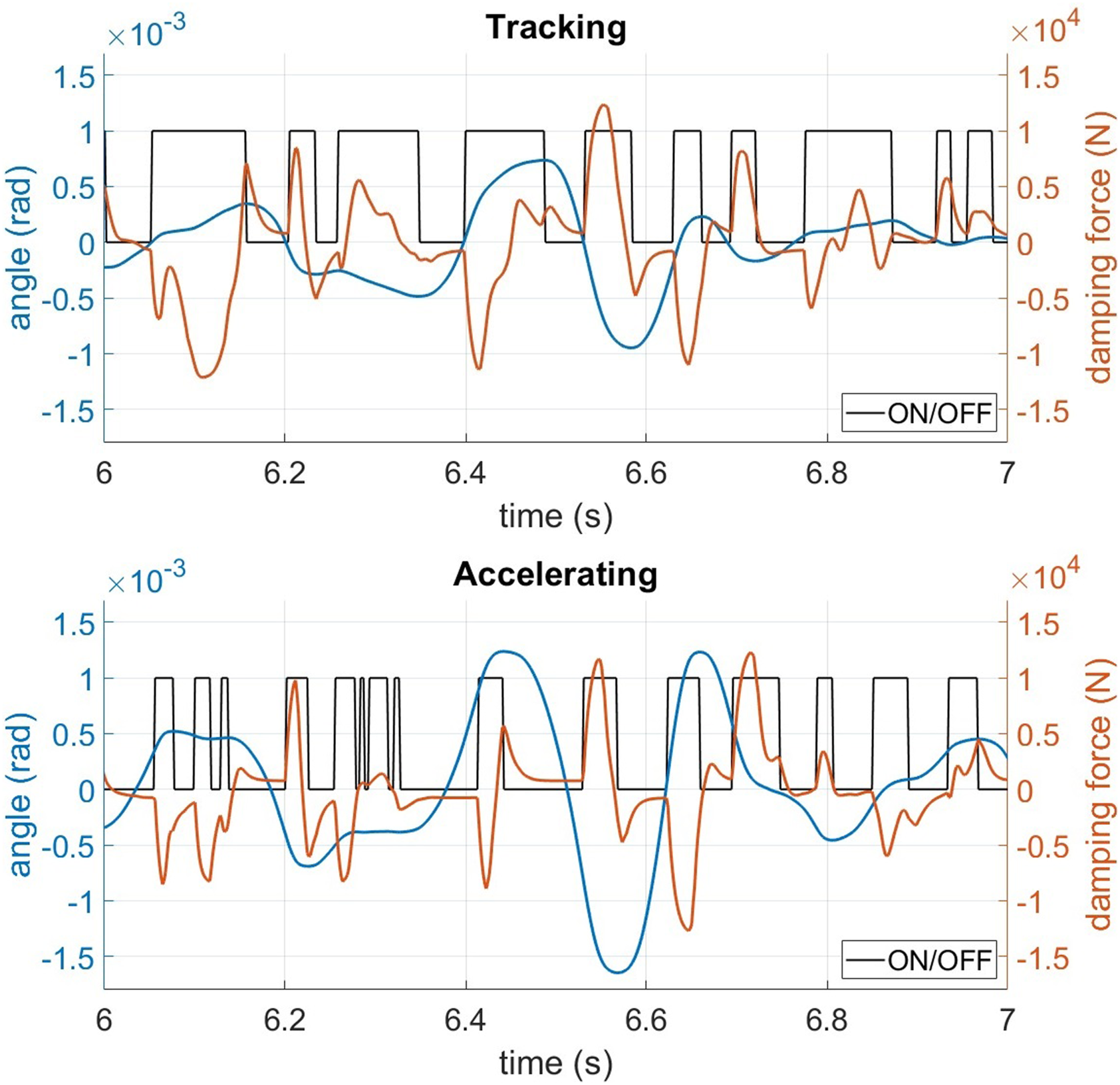
Figure 8 then shows the course of one of the monitored quantities (wheelset lateral displacement) for the selected setting and its moving RMS, according to which the contribution of S/A damping is evaluated. The course of vehicle body lateral acceleration (thin line) and its moving RMS (thick line) for the algorithm Tracking (damper force level 100%, time constant 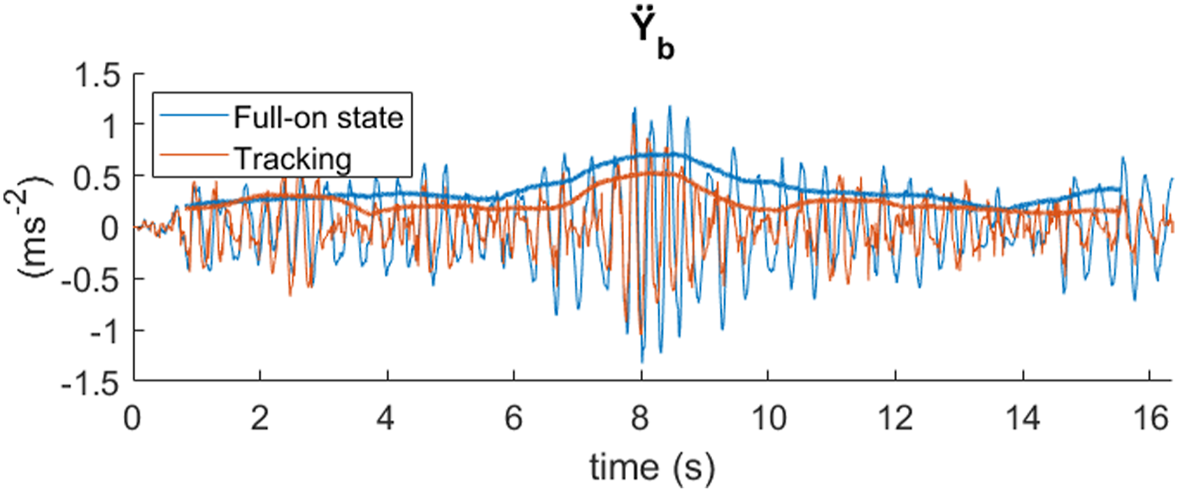
3.1.1. Higher equivalent conicity
Figure 9 shows a comparison of the reached maximum value of the moving RMS for the studied parameters, for higher equivalent conicity ( The dependence of studied quantities maximal moving RMS on damper force level and time constant for all control strategies at higher equivalent conicity.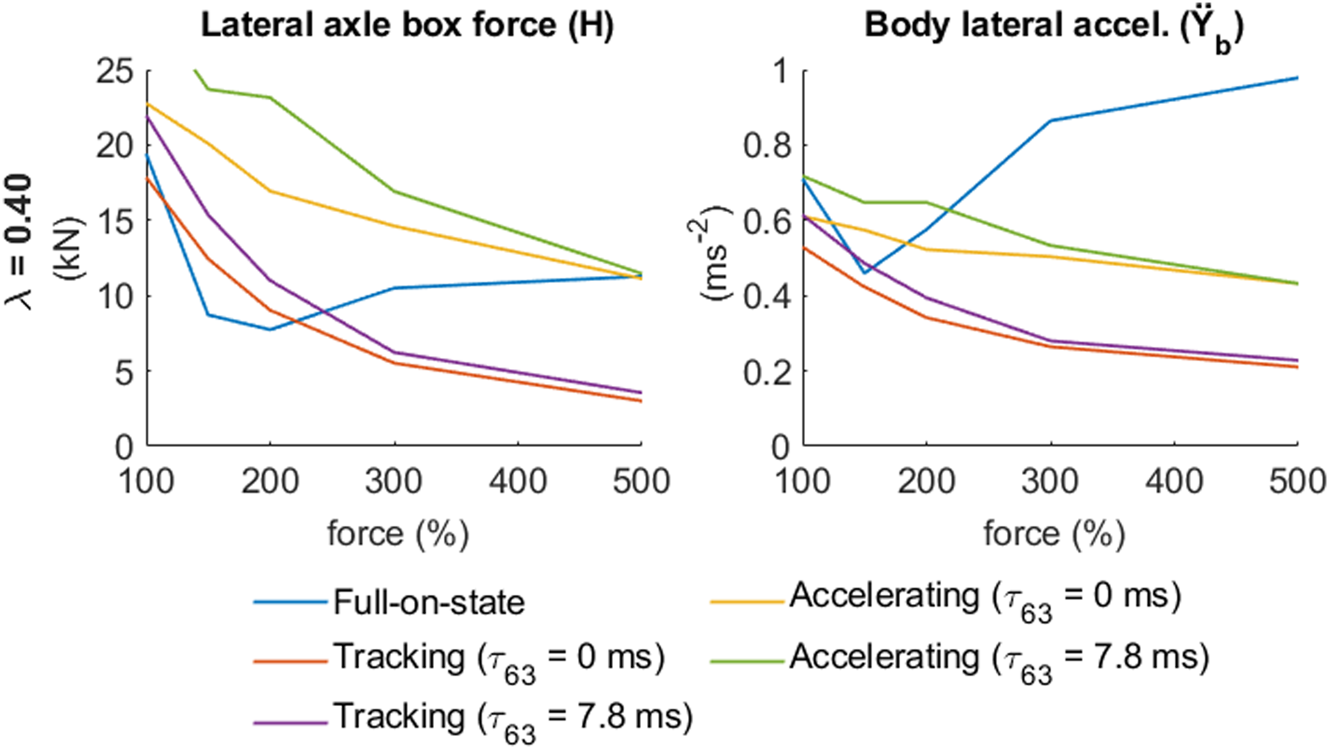
Improvement of maximal moving RMS of studied quantities for algorithms Tracking and Accelerating compared to Full-on state, when equivalent conicity is
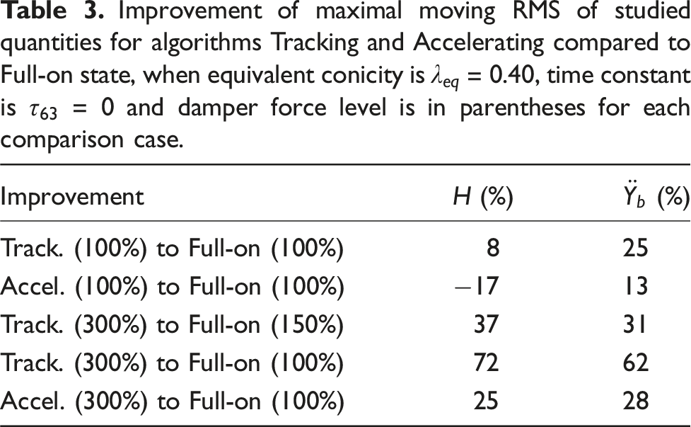
It can be concluded that the nominal damper force level is not the best way for either control mode, see Figure 9. The Full-on-state mode works best with a 150% damping force level. The Tracking and Accelerating algorithms improve the vehicle behaviour until the damper force level reaches 300%. After exceeding this value, the improvement is only small. Therefore, if the performance of the Tracking algorithm is compared with the Full-on state for the ideal damper force levels, improvement is as follows (Table 3).
However, the original passive damper corresponds to the MR damper with a damper force level of 100%. If the ideal performance of control strategies is compared with the Full-on-state mode with the nominal damper force level, the improvement of both S/A algorithms is large, see Table 3 and Figure 9.
3.1.2. Medium equivalent conicity
Simulations showed similar results for medium equivalent conicity as for higher equivalent conicity for both S/A algorithms. Vehicle stability and vehicle body lateral acceleration are improving with increasing damper force level up to about 300%, after which the improvement is only small. However, in contrast, Full-on-state works best with a damper force level of 100% (from tested force levels), see Figure 10. The dependence of studied quantities maximal moving RMS on damper force level and time constant for all control strategies at medium equivalent conicity.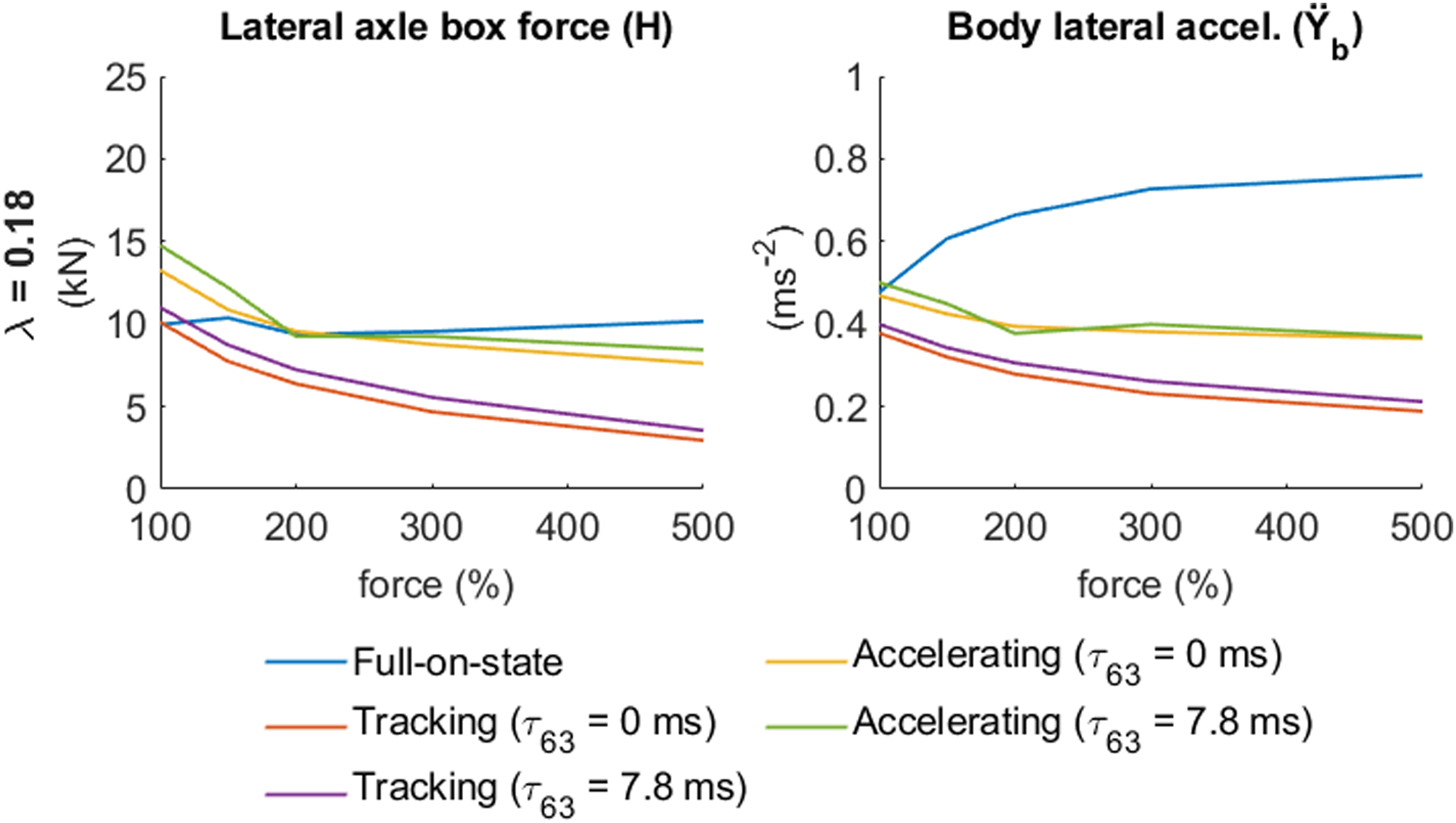
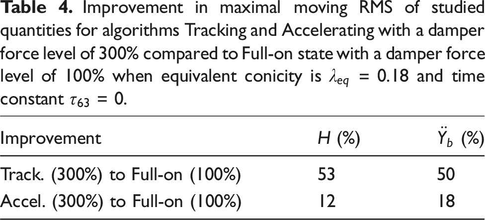
Improvement in maximal moving RMS of studied quantities for algorithms Tracking and Accelerating with a damper force level of 300% compared to Full-on state with a damper force level of 100% when equivalent conicity is
However, the overall level of reached values of the observed quantities is lower than in the case with a higher equivalent conicity. Therefore, this equivalent conicity case is not so significant from the perspective of the assessment of the running behaviour.
3.1.3. Low equivalent conicity
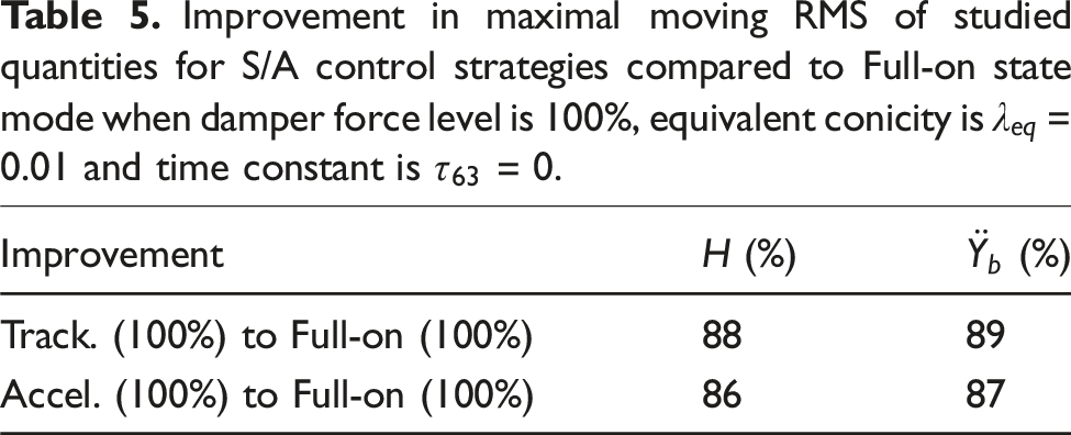
A substantial improvement in the running behaviour of the investigated vehicle is achieved in the case of a low level of equivalent conicity ( The dependence of studied quantities maximal moving RMS on damper force level and time constant for all control strategies at very low equivalent conicity. Improvement in maximal moving RMS of studied quantities for S/A control strategies compared to Full-on state mode when damper force level is 100%, equivalent conicity is 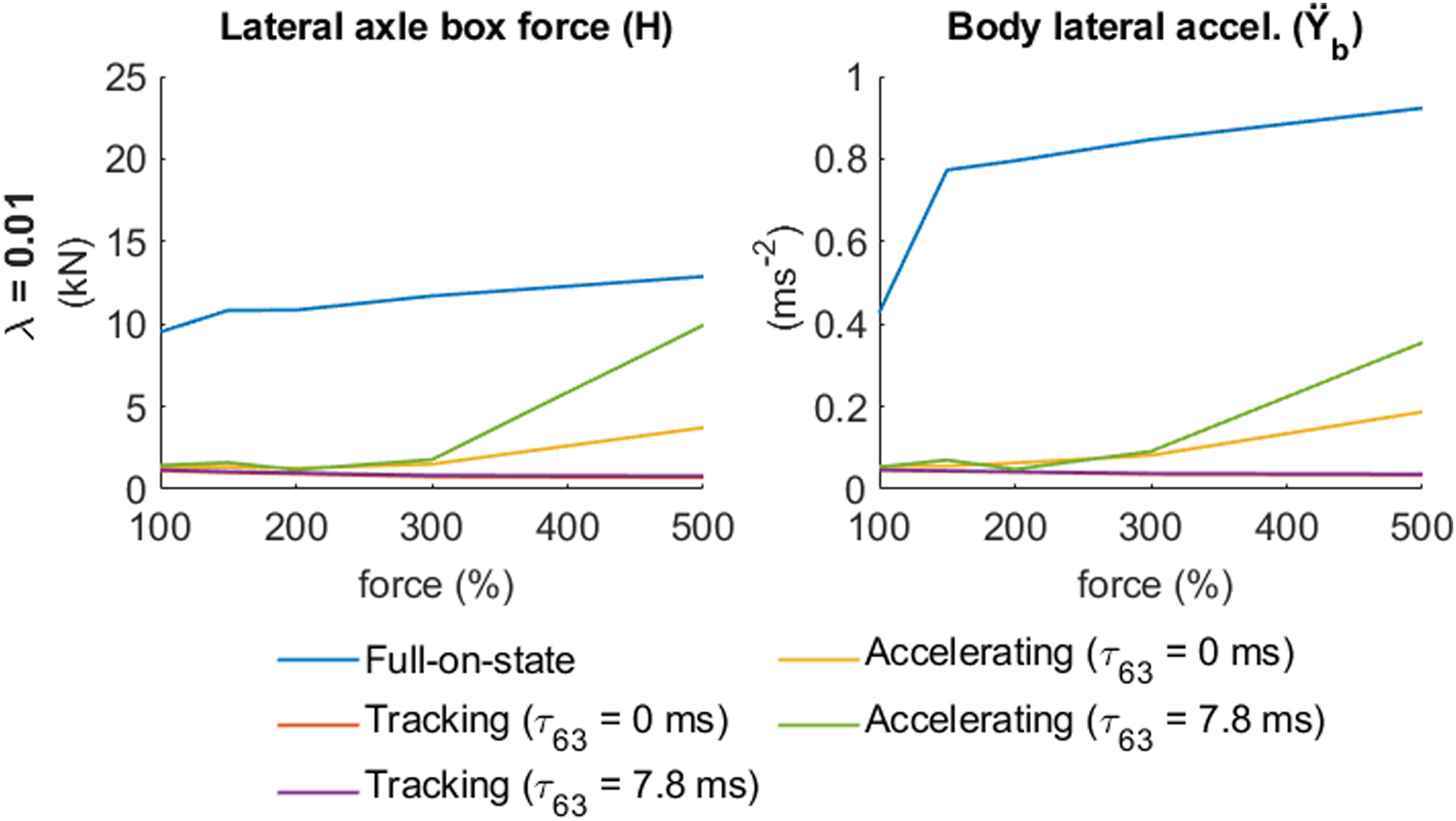
3.1.4. Another finding
Reducing vehicle body transverse vibrations is comparable to the use of secondary lateral MR dampers (Codecà et al., 2007; Hudha et al., 2011; Shin et al., 2014). It is an interesting result because the bogie yaw damper does not directly affect the transverse motion of the body. In addition, the running behaviour (running stability expressed by lateral axle box force) has improved when the locomotive runs at subcritical speeds, which these publications do not evaluate.
The influence of the time of the damper transient response on the damper efficiency is important. At 100% of the damper force level, the damper time constant of 7.8 ms leads to a 23% reduction in stability compared to the time constant of 0 ms at higher equivalent conicity when the Tracking algorithm is used (see Figure 9). However, the stability reduction caused by the damper time constant is negligible for a damper force level of 300% or more.
3.2. Theoretical stability analysis
Figure 12 shows the simulation results of the theoretical stability analysis of the vehicle performed on the ideal straight track at decreasing speeds. This analysis was carried out under the conditions of a higher level of equivalent conicity ( Dependency of the third wheelset lateral motion amplitude on the vehicle speed in the stability analysis on the ideal track at decreasing speed for all control strategies with damper force level of 100% and time constant 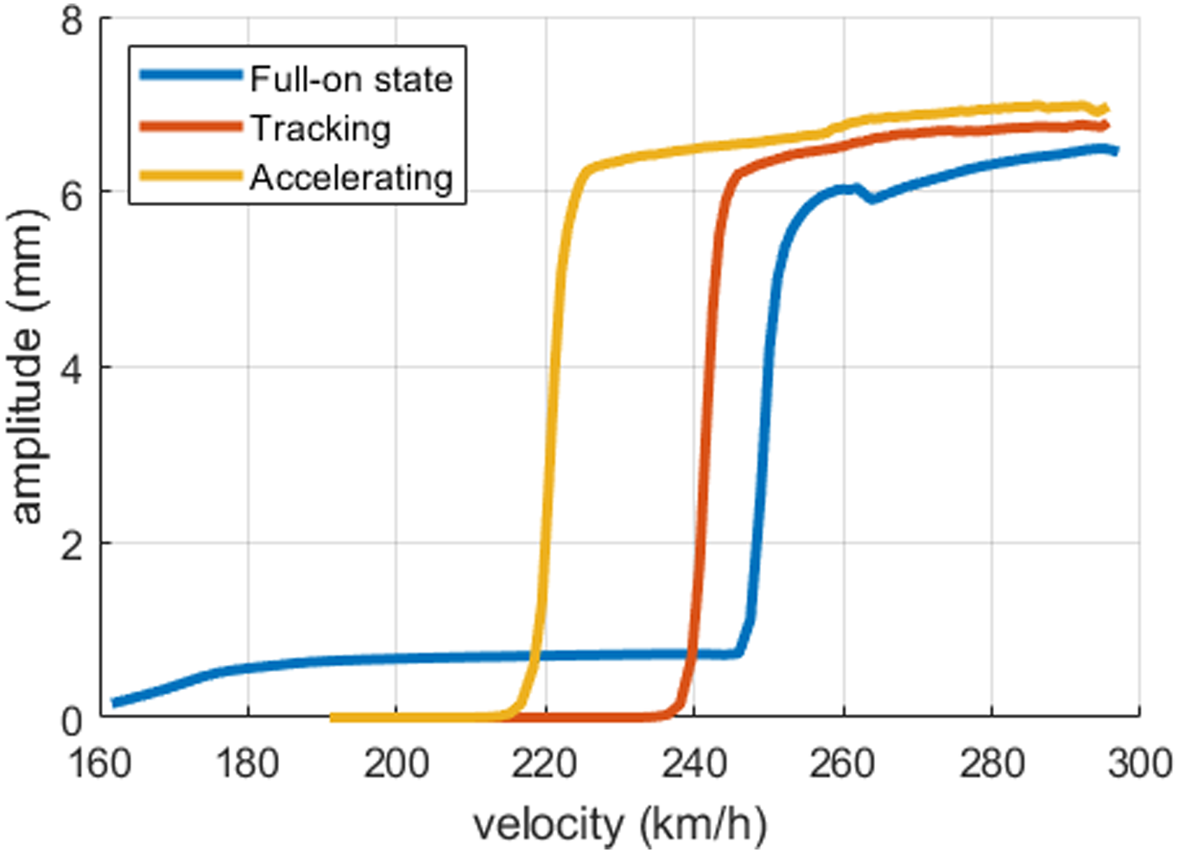
It can be stated that under the considered conditions, no increase in the vehicle’s critical speed using S/A control was observed (in comparison with the Full-on state mode). Locomotive shows a critical speed of approximately 250 km/h in the Full-on state, ca. 240 km/h for the Tracking algorithm and only ca. 220 km/h for the Accelerating algorithm. But in all these cases, the critical speed is higher by at least 10% than the planned maximum speed of the vehicle (200 km/h).
However, attention should be paid to the fact that the locomotive equipped with passive dampers shows a range of speed (approx. 160 up to 250 km/h) with a stable lateral oscillation of individual wheelsets with a small amplitude, both proposed algorithms for semi-active yaw damper control led to the elimination of these oscillations.
Figure 13 shows the dependence of the theoretical critical speed on the damping force level for all three control strategies and for time constants of 0 and 7.8 ms under a higher level of equivalent conicity 𝜆eq = 0.40. Indeed, it is possible to increase the critical speed for Full-on-state mode only by 20 km/h to 270 km/h using a damper force level of 150%. The vehicle loses stability as the damping force level increases by over 150%. Dependency of theoretical critical speed on the damping force level for all control strategies and for time constant 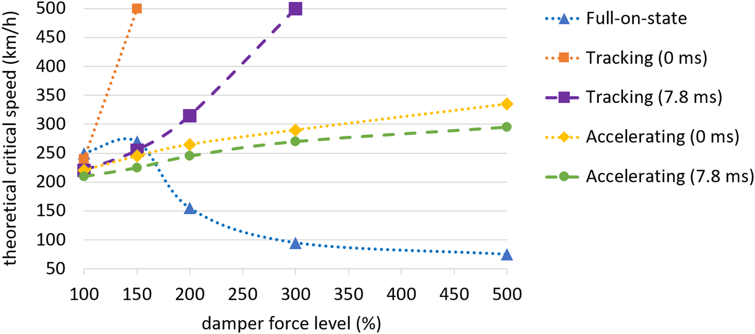
However, in the Tracking algorithm case, it is possible to increase the critical speed beyond the investigated range, which means critical speed can increase by at least 250 km/h to 500 km/h, already with a damping force level of 150% at a time constant of 0 ms. With a time constant of 7.8 ms and a damping force level of 200%, it is possible to increase critical speed to 315 km/h, and for 300%, it is at least 500 km/h again.
In the Accelerating algorithm case, the critical speed increases with increasing damping force level to 335 km/h (damping force level of 500%,
4. Conclusion
This paper is the first to deal with the semi-active control of a magnetorheological bogie yaw damper of a railway vehicle. The paper proposes two new control algorithms and thoroughly examines their performance under a wide range of conditions. With a semi-actively controlled MR bogie yaw damper, it is possible to improve the railway vehicle running stability, which is related to increased ride comfort, and increased critical speed. The key findings of the paper are as follows: • Under conditions of a higher equivalent conicity • When using the MR damper of ideal damper force level, it is possible to reduce the lateral axle box force by 72% and vehicle body acceleration by 62%, compared to the MR damper of nominal damping force level in the passive mode, at higher equivalent conicity. • The vehicle’s dynamic properties are most significantly improved under the conditions of low equivalent conicity • When increasing the damper force level to 300% or more, the current time constant of • It would be advisable to shorten the time constant for the MR damper with the nominal damping force. • When using S/A control of yaw dampers, the vehicle’s behaviour improves as the damper force increases. Conversely, in Full-on-state mode, above 150% of the damper force level, the vehicle’s behaviour worsens sharply. • With a passive damper, increasing the critical speed only to 270 km/h by increasing the damping force level to 150% is possible. With the same damping force level, S/A control can increase critical speed to over 500 km/h. • These facts are useful for current vehicles and also for the new generation of high-speed vehicles, which will have to have a running gear adapted to higher forces from the bogie yaw damper than current vehicles.
The more efficient of the two proposed algorithms (Tracking) needs perfect prediction of the rail axis position angle as input. The second algorithm (Accelerating) uses easily available quantities but achieves worse results. So, perfect prediction of the rail axis and design of proportional S/A control will be a part of future research. Furthermore, better results can be expected when a more advanced algorithm is proposed to change the MR damper force proportionally (not just on/off).
This paper does not deal with the vehicle behaviour in the curve. It is assumed that S/A control of bogie yaw dampers decreases the guiding forces in small radius curves and switches. The second option is to deactivate yaw dampers in the range of lower speeds (where the question of vehicle running stability is not critical), thus reducing the negative effects of bogie yaw dampers. The behaviour of a railway vehicle equipped with the MR bogie yaw damper when negotiating an S-curve will be described in another paper.
Footnotes
Declaration of conflicting interests
The author(s) declared no potential conflicts of interest with respect to the research, authorship, and/or publication of this article.
Funding
The author(s) disclosed receipt of the following financial support for the research, authorship, and/or publication of this article: This work was supported partly by Technology Agency of the Czech Republic under Grants CK03000052 and CK04000210, and partly by Brno University of Technology under Grant FSI-S-23-8212.