
Abstract
Aiming at a more efficient and accurate performance of parallel manipulators in the existence of complex kinematics and dynamics, a robust generalizable methodology is proposed here for an integrated 6-DOF Stewart platform with rotary time-delayed actuators torque control. The suggested method employs a time-delay linear–quadratic integral regulator with online artificial neural network gain adjustment. The unknown time-delay is estimated through a novel robust adaptive estimator. The global asymptotic stability of the estimator is proved via a Lyapunov function. The controller is developed in MATLAB software and implemented on the robot designed in ADAMS software to ensure that the real-time tracking error of a nonlinear system with an unknown time-delay is kept to a minimum. The sensitivity of the controller to the parameter choices is studied via implementing the controller in ADAMS software and is validated by investigating the performance on a naturalistic fabricated robot. The approach is assessed using simulation and experimental tests to show the feasibility, optimum, and zero-error convergence of the technique developed.
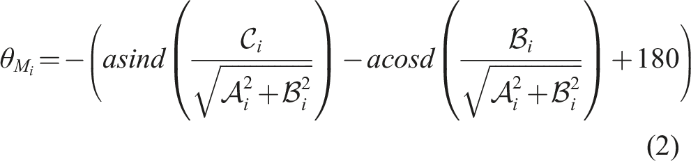
1. Introduction
Parallel mechanisms over serial manipulators are alternatively suggested in applications such as surgeries (Orekhov et al., 2016; Saeedi-Hosseiny et al., 2021; Tajdari et al., 2020b) and scanning (Huang et al., 2018; Lee et al., 2022) which require higher acceleration and speed, better accuracy, and lighter weight (Taghirad, 2013). In particular, the highly precise scans of the human body for surgeries, the creation of anatomically adaptable rehabilitation devices (Nomura et al., 2016), and the next generation of Ultra Personalized Products and Services (UPPS) (Minnoye et al., 2022) attract more interest according to the necessity of robot-influenced health and human survival. One challenging scanning scenario as the implementation candidate for this study is rapid automatic breast scanning (Sun et al., 2018), although it is a very complex operation due to the flexibility and deformability of the breast tissue, particularly in motion scanning. The high accuracy requires a clear understanding of the control of such parallel robots that investigate complex dynamic, sophisticated control approaches (Shoham et al., 2003), and implementation objections such as a sensor or actuator time-delays (Jin et al., 2017).
The key goal of parallel robot control design is to achieve an exact continuation of the target direction and orientation of dynamic or static variables in the robot’s moving end-effector (Merlet, 2006). While multiple control systems (Ju et al., 2022), such as optimal feedback robotics control (Tourajizadeh et al., 2016), monitoring backstage adaptive control (Huang and Fu, 2004), sliding mode (SM) (Zhu et al., 2022; Tajdari et al., 2017a), model predictive control (Hu et al., 2022), and PID controllers (Velasco et al., 2020), are available, fewer control procedures are utilized for Stewart robots with rotary actuators because of the extra complexity of the robot’s dynamics. The reverse dynamic control methods are especially important for controlling the motion of the end-effector directly through the manipulators. The rotary robot torque control, which is an opening for further application of identification techniques, nonlinear control methods, and impedance manipulator control, is explored in limited studies (Yang et al., 2019).
Moreover, among the state-of-the-art studies that addressed the control of the rotary Stewart robot, few of them investigated the time-delay as an undeniable part of such robots emphasizing high accuracy. Time-delay control (TDC) is often an efficient way of tackling the issues listed above. The TDC scheme is widely utilized for significant applications, such as robot manipulators (Baek et al., 2021), underwater vehicles (Qi and Cai, 2021), and robots with flexibilities (Xu and Xu, 2022). Meanwhile, the use of time-delayed control commands will necessarily profit estimation errors, that is, time-delay estimation (TDE) errors, in practical control methodologies implementations.
In presence of high uncertainties and nonlinearities, for example, saturation, the TDE errors will be increased which causes instability of the closed-loop control system. Thus, the TDC approach is mainly employed as a general solution that benefits from its model-free feature. Additional robust control strategies, such as SM control (Li and Chen, 2018), terminal SM control (TSM) (Fu et al., 2022), and adaptive robust control (Ma et al., 2018), are now also being employed to ensure high precision and robustness. Because of the model-free TDE approach and the employed robust control techniques, TDE-based control schemes may provide great control efficiency straightforwardly. The bulk of current TDE-based control schemes, on the other hand, is strictly confined to constant control gain, ensuring that fixed gain is always utilized. However, time-varying dynamic disruptions usually occur in practical implementations, which may result in the control output degrading. As previously mentioned (Wang et al., 2018a), control precision is roughly proportional to control of the gain. With a greater control gain, better control precision and faster dynamical reaction are feasible. Moreover, there will be a significant noise effect, as well as control device instability, when an inappropriately high control gain is used. Similarly, when the control gain is set too low, the control scheme degrades and may even fail to track the desired trajectory. Because control tasks and requirements for parallel manipulators vary with time, maintaining adequate detailed control output under complicated situations while utilizing a fixed control gain is typically quite challenging. As a result, adaptive TDC (ATDC) methods with self-tuning power gain have been suggested and investigated to solve the aforementioned concerns (Baek et al., 2017; Tajdari and Toulkani, 2021). However, it is challenging to utilize in real applications due to its inherent noise susceptibility and the usage of many control settings. As a result, the built algorithm was only demonstrated using simulations with a single degree of freedom (DOF). Then, for the control gain (Baek et al., 2017), an auto-tuning algorithm was developed. Although the ATDC systems discussed above have produced intriguing theoretical and experimental findings, the disadvantages are several (Wang et al., 2018b): First, the adaptive legislation that has been suggested cannot quickly and accurately reflect the tracking error (Jin et al., 2016), or might create significant chatters owing to the usage of the discontinuous function, and second, the designed ATDC schemes (Baek et al., 2017) used traditional linear ATDC schemes.
This paper seeks to establish and test for the complex parallel structure of a novel robust torque control approach in presence of huge time-delay with the actuators to optimize torques and reduce tracking errors in order to resolve all the challenges listed above. Moreover, the controller is validated through a valid nonlinear test-bed through the ADAMS model proposed in Tajdari and Toulkani (2021) and assessed experimentally via a fabricated robot. In Tajdari et al. (2020a) and Tajdari and Toulkani (2021), a robust optimal torque controller for the same Stewart platform is discussed; however, the works did not investigate the impact of time-delay on the performance of the robot and also optimal design of the platform which are extensively studied in this paper. In addition, an introductory version of this study is presented in Tajdari et al. (2021), which is collaborated here with optimal design of the robot dynamic; architecting of a robust estimator for the time-varying time-delay; a more rigorous concept; a comprehensive verification on the stability of controller parameters for the proposed control law; studying on the degree of robustness regarding parameter selection via numerical experiments; and extra numerical experiments, including a scenario grants a state-of-the-art regular control method and a scenario, which contains extra disturbances via the fabricated robot.
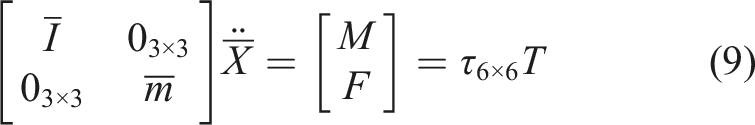
2. Equation of motion
2.1. Kinematics equation
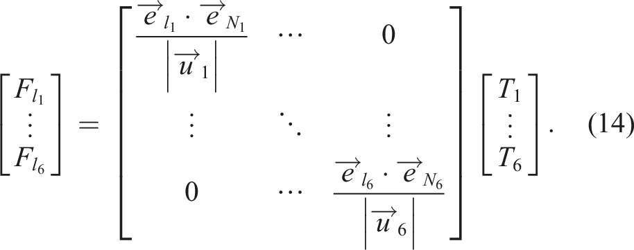
The torques manipulated with motors and their rotational angles are the variables capable to be controlled in a Stewart platform that is actuated with rotary motors. A relationship between the variables of the motors and the location of the end-effector is reported as follows The Stewart platform mechanism: (a) defined variables and vectors and (b) the top view of the designed Stewart platform in SolidWorks software.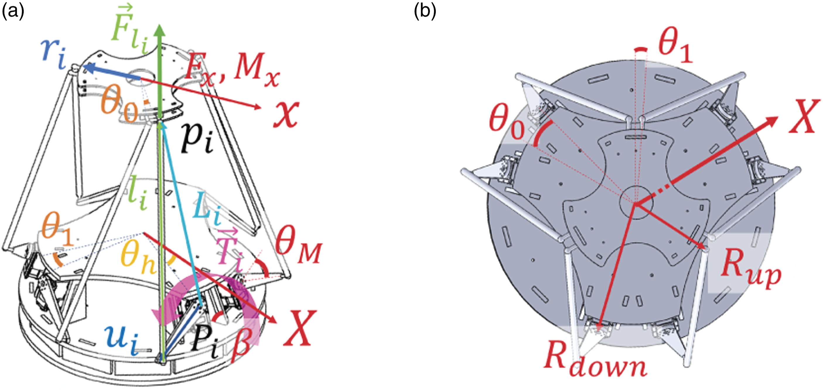

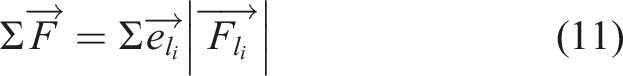
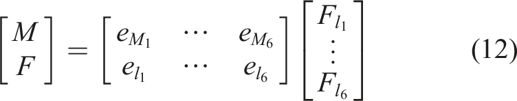
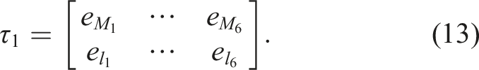
2.2. Kinetics equations
Here, employing the Newton–Euler method, the dynamic formulation of the Stewart platform equipped with six rotary motors is concluded from Van Nguyen and Ha (2018); Szufnarowski (2013). The platform includes, as shown in Figure 1, a moving plate as the end-effector, a sedentary plate as the base, six rotary actuators as manipulators to move the end-effector, and six legs connected to their corresponded motors. The spherical joints are utilized to carry the end-effector and the backbone to the six legs.
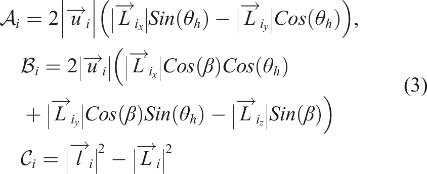
The formulation extraction is summarized to introduce the different complex properties of the structures and outcomes. The analyzed Stewart platform is drawn in Figure 1(a). The kinetics formulations regarding the end-effector are extracted as


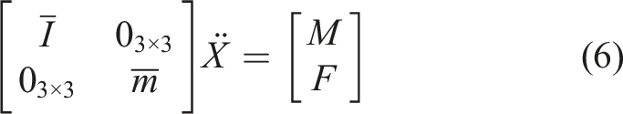


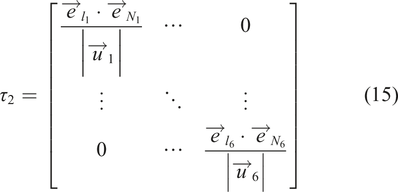
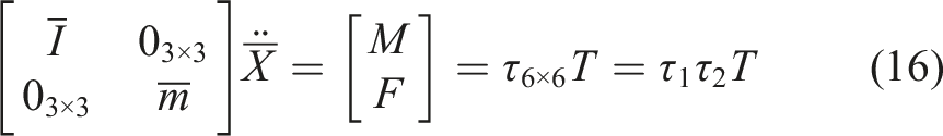
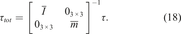
Considering

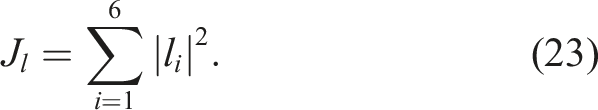
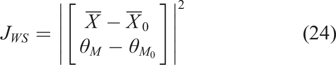
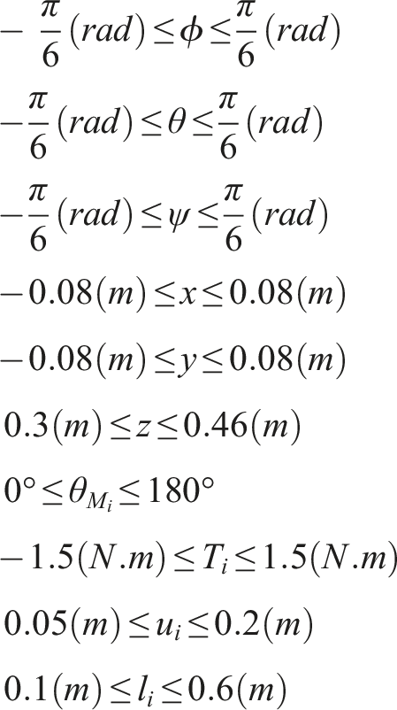
2.3. Optimal design of the dynamic robot platform
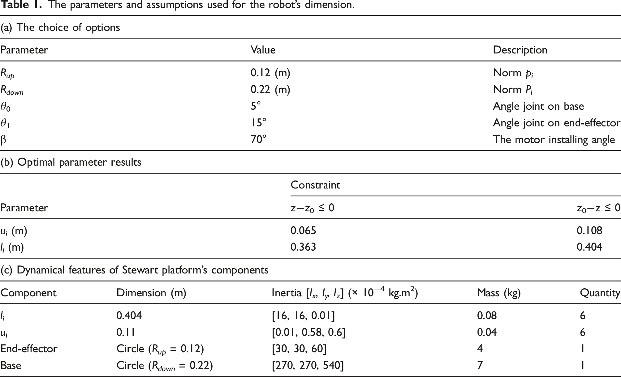
The parameters and assumptions used for the robot’s dimension.
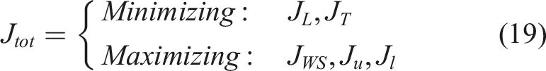
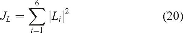
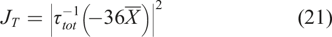
Regarding the maximization, the moving links’ cost functions are assumed as below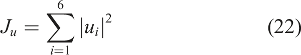

2.4. Nonlinear model
In terms of controller assessment, it is necessary to prepare a realistic nonlinear model that can describe the actual robot. As certain dynamical constraints, for example, the collision of objects, stiffness, and elasticity of rigid bodies, and friction between hard surfaces, are not easy to be modeled in MATLAB software; an ADAMS model (Tajdari and Toulkani, 2021) is established based on the optimally designed dimensions in the Optimal Design of the Dynamic Robot Platform section. Since the ability to encrypt and apply multiple control methods in ADAMS software is missing, the model is controlled online with MATLAB software. Second, the machine 3D model in the SolidWorks program is shown in Figure 1(b). Then, the 3D model can be imported into ADAMS and the aforementioned constraints in the Kinetics Equations section are applied to the model of the robot, such as joint sizes, materials, body densities, rigidity towards each other, and friction between hard surfaces. The parameters in Figure 1(b) and Figure 1(a) are explained in Table 1(a), and Table 1(c) reports the used dynamic parameters. According to the table, the platform includes 14 components of mass and moment of inertia.
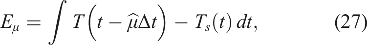
3. Adaptive time-delay estimator design
We aim at designing a novel adaptive estimator to estimate the actuators’ time-delay. To do so, the needed assumptions are presented, and then the integration of the method to the designed time-delay optimal controller is explained, and ultimately, the convergence of the estimated time-delay value and the method’s global asymptotic stability are investigated. In total, by comparing the designed torque (T) and measured used torque (T
s
) on the actuators, the estimator defines the exact value of the time-delay for each motor. Let us define the integral error states (E
μ
)


A model reference is considered as


4. Discussion
A value of 0.5 is added to
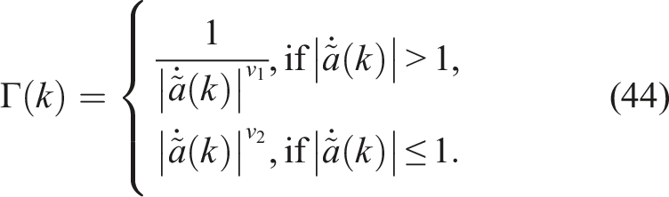
In (44), ν1 and ν2 are very effective to the changes of Γ by the time. And, the huge parameters of Γ can lead the system to an unstable condition as the system and control scheme is very dependent on the estimated time-delay. Thus, Γ should be chosen so that the estimator is fast enough with the least overshoot. For the possible domain of ν1 and ν2, four conditions exist according to (44) as follows. 1. ν1 < 0 and ν2 < 0: Which is unstable as Γ would be very big number; thus, we have overshoots. 2. ν1 < 0 and ν2 > 0: For some cases that 3. ν1 ≥ 0 and ν2 ≥ 0: Some stable points may be found here as with this condition, Γ is bounded. 4. ν1 > 0 and ν2 < 0: For small values of
Accordingly, in this study, the proper values of ν1 and ν2 are investigated in condition 3, as they will be explained in the Sensitivity Analysis section.
5. Controller design
Because the developed dynamic platform in the ADAMS software in Tajdari and Toulkani (2021) consists of the nonlinear parameters of the actual platform, this is accurately a nonlinear Stewart system, and the proposed controller must be able to penalize tracking errors in the presence of nonlinearities to monitor those systems (Åström and Hägglund, 1995). In addition to the robustness, parallel manipulator input signals optimization is a problem to be tackled during the control design process. Therefore, an optimal control scheme for the linear–quadratic integral (LQI) is an appropriate choice for the nonlinear control problem.
5.1. State-space equations
The state-space and dynamic equations of the Stewart robot can be established as below


Thus, by integrating the integral states into the state-space formulation, the final dynamic error of the system is proposed as
5.2. Time-delay control scheme
By assuming a time-delay of η for the system in (52) (η is the summation of all the delays including actuator and sensor), the time-variant form of the system is written as
Accordingly, the solution for the well-known differential equation in (55) is presented in Karafyllis and Krstic (2013)

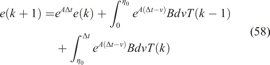
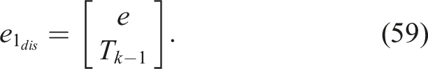
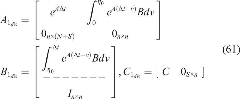
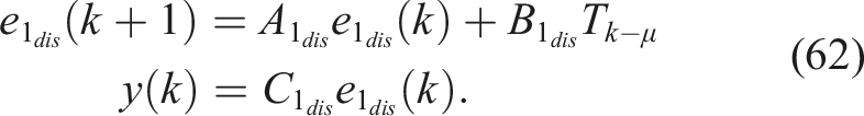
Then, the state-space in (58) is formulated as
Now, the following quadratic cost function (Tajdari et al., 2019) can be defined over an infinite time horizon, which is determined for the minimization of all states and control inputs

A linear–quadratic regulator (LQR) is used to solve resultant optimal control problems (66), (67), in which the goal is to stabilize feedback gains via the assumption considering the stability and detectability conditions, fulfilled according to Tajdari et al. (2020a) via the Hautus test (Williams and Lawrence, 2007).
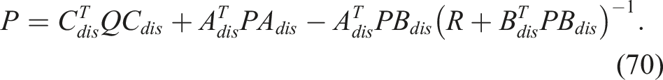
5.3. Controller gains
In order to solve the LQI problem, a linear feedback control law is proposed as follows


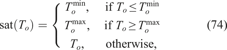
5.4. Anti-windup approach
In functional implementations, due to complexities such as input saturation problems, exact values of the desired states cannot always be obtained. Therefore, the anti-windup system has been incorporated as investigated in Åström and Rundqwist (1989), into the proposed controller. The scheme amends the integral part of the dynamic controller (72) as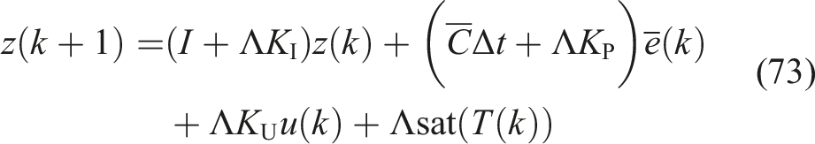
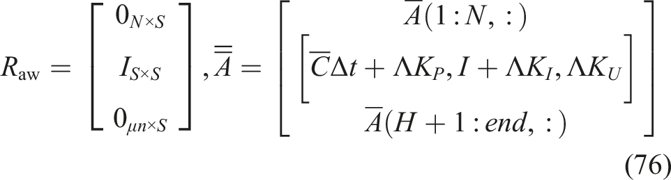
5.5. The closed-loop anti-windup system stability analysis
A main restriction to the consistency of the closed-loop structure conveys the matrix Λ, which implies that the stable eigenvalues of I+ΛKI are 

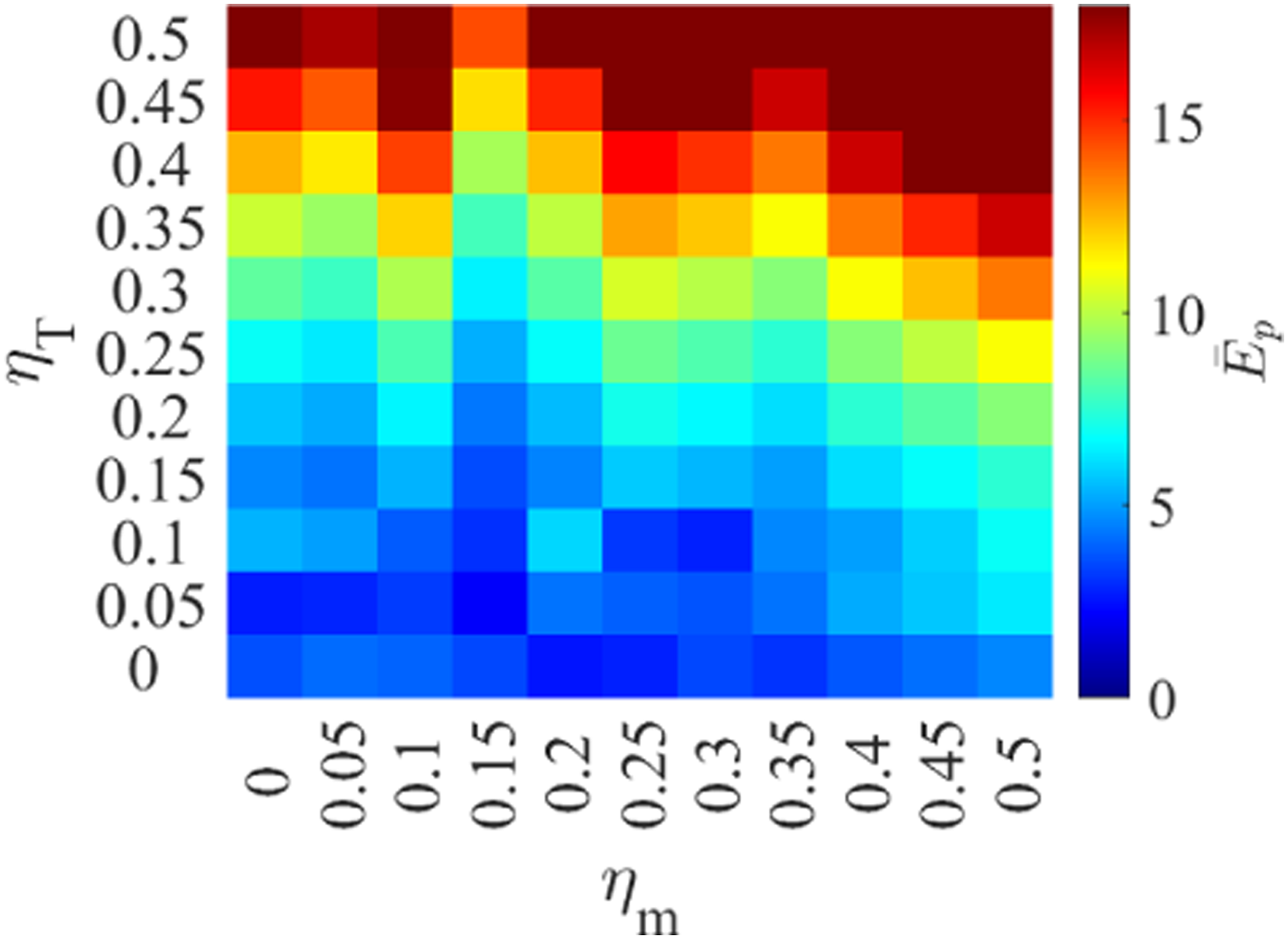
5.6. Sensitivity analysis
To evaluate the suggested technique, the dynamic compensators (72) and (73) are added to the nonlinear ADAMS model, while Numerical analysis: Sensitivity analysis based on 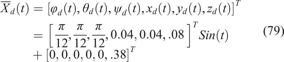

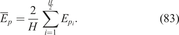
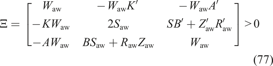
In line with the Closed-Loop Anti-Windup System Stability Analysis section, the stability of the closed-loop system is investigated. In other words, it evaluates if the Ξ matrix in (77) is a positive definite matrix for a large variety of
In addition, the sensitivity of the delayed steps to the performance of the robot reveals the allowed domain of delay which should be considered in the design of the robot during the motor selection process. To this end, a set of experiments is performed to investigate the effects of μ in domain of 0–100 in terms of
5.7. ANN estimator design for w Q and w R
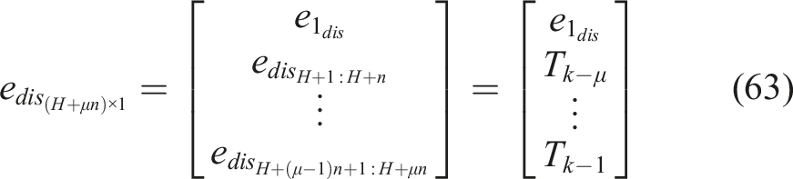
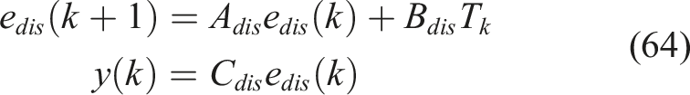
Since the parameters of dynamic equations in (46) are time-variants, B
dis
(k) in (64) is accordingly time-variant regarding (49). Thus, in answer to the particular direction, it is theoretically assumed that the mechanism has different behavior in different directions. Accordingly, the use of intelligent methods means nonlinearity of the mechanism and the optimization process, and complexity of the problem. Since the cost function of the optimal problem in (66) is based on w
Q
and w
R
, estimating the true values of w
Q
and w
R
in each step is a solution to the nonlinearities, where w
Q
determines the degree of the penalization of the error of the states, and w
R
optimizes the torques built. An advanced artificial neural network (ANN)–based input–output estimator is therefore designed to estimate w
Q
and w
R
online, where state error functions and torque functions are selected parameters as the estimator’s inputs. The functions introduced in Tajdari and Toulkani (2021) imply that for any arbitrary variable of ϵ, the density function is The schematic structure: (a) designed ANN estimator structure and (b) closed-loop control diagram. Structural information.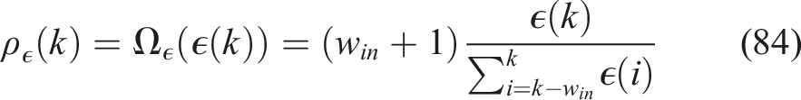
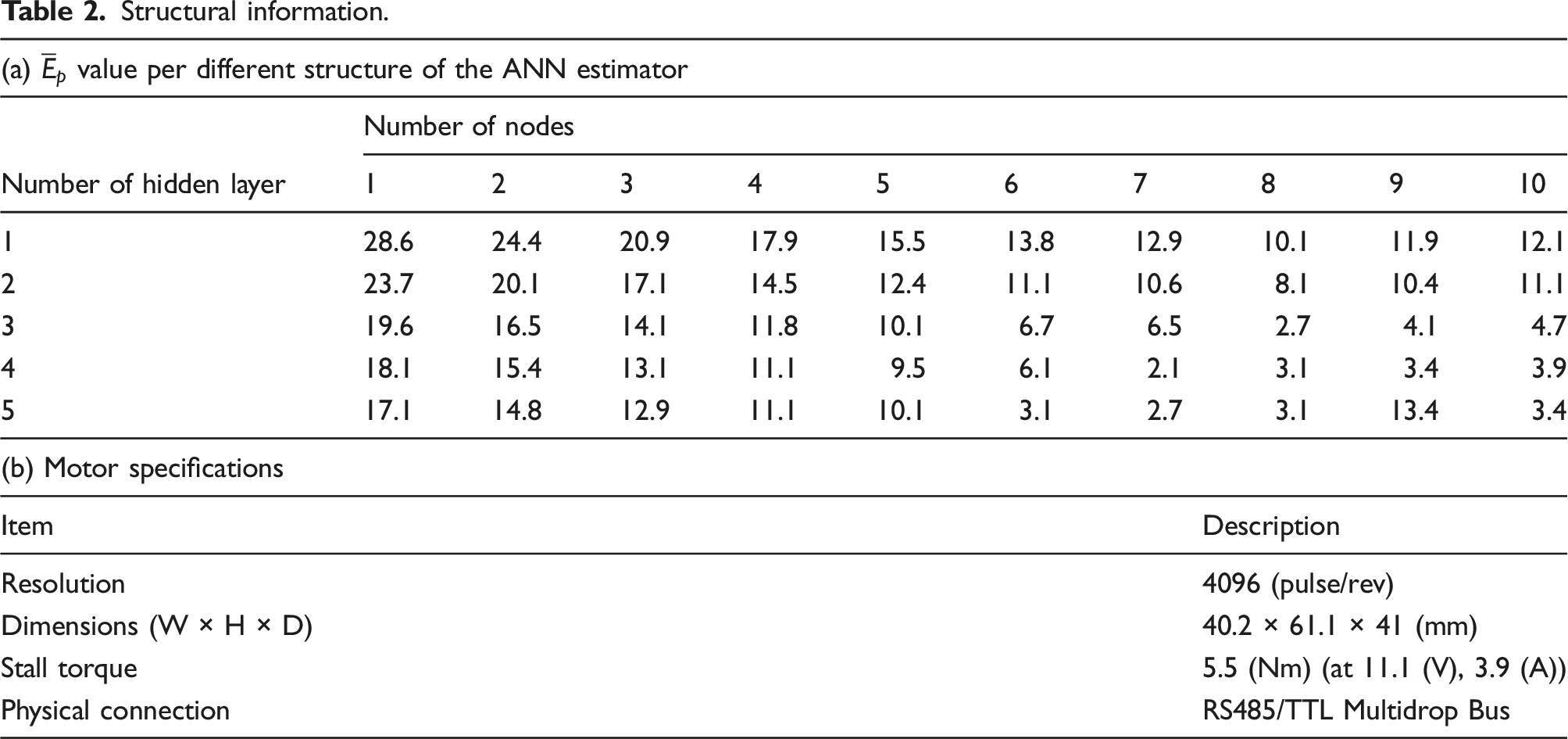
To assess the stability of the final structure of the ANN estimator, the input section of the training data-set is used as the input of the estimator, and the output of the estimator is compared with the output section of the training data-set. For the comparison, mean absolute percentage error (MAPE), Standard deviation error (SDE), and correlation coefficient (R2) are used which are explained in Ghaffari et al. (2018). Accordingly, the estimator has an average value of 0.081 and 0.064 in terms of MAPE and SDE, respectively, explaining a small error with the desired output data. In addition, the R2 average value of 0.98 defines a high correlation between the output of the estimator and the desired output data, which shows a stable performance of the estimator.
5.8. Robustness level
In order to evaluate the degree of robustness of the controller to the unknown disturbances and uncertainty, the closed-loop control system is experimentally assessed with the parameters discussed in the Sensitivity Analysis section through the ADAMS model in presence of white noise with a variety of amplitudes both on the input torque of the system and the mass value of the end-effector. Accordingly, the implemented torques (T(k)) in (75) and mass (m) in (18) are replaced with Reported 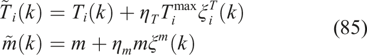
6. Experiment setup
The robot in Figure 1 is generated to test the controller in an actual nonlinear system of natural disturbances. As shown in Figure 5, 6 servo motors of mx-64, with the specifications explained in Table 2(b) of Robotis (2019), are used as torque manipulators and are operated directly by MATLAB software through USB2Dynamixel (Robotis, 2019). In addition, a 9-DOF absolute IMU fusion breakout-BNO055 is used to calculate the end-effector position and angles Fabricated rotary parallel robot.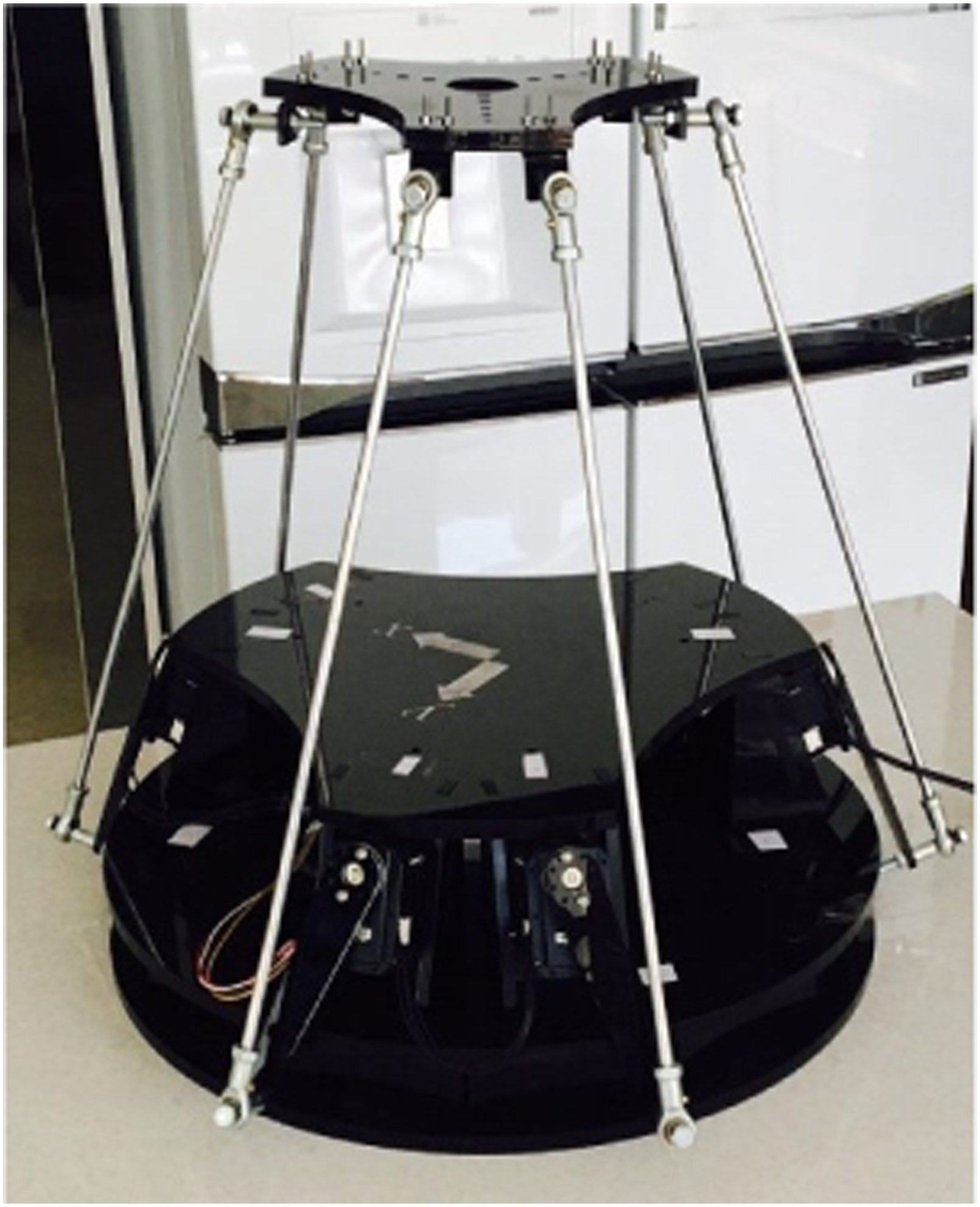
7. Results
The simulation and experiment results are generated by implementing the proposed controller (72), with integral states in (73), where w
in
= 30, μ = 8, Δt = 0.1 s, • Controller i: LQR controller. • Controller ii: LQI controller without anti-windup scheme. • Controller iii: Time-delay LQI controller with anti-windup scheme. • Controller iv: Time-delay LQR controller with ANN estimator. • Controller v: Time-delay LQI controller with ANN estimator and with anti-windup scheme. • Controller vi: Time-delay LQI controller with ANN estimator and without anti-windup scheme.
7.1. Simulation results
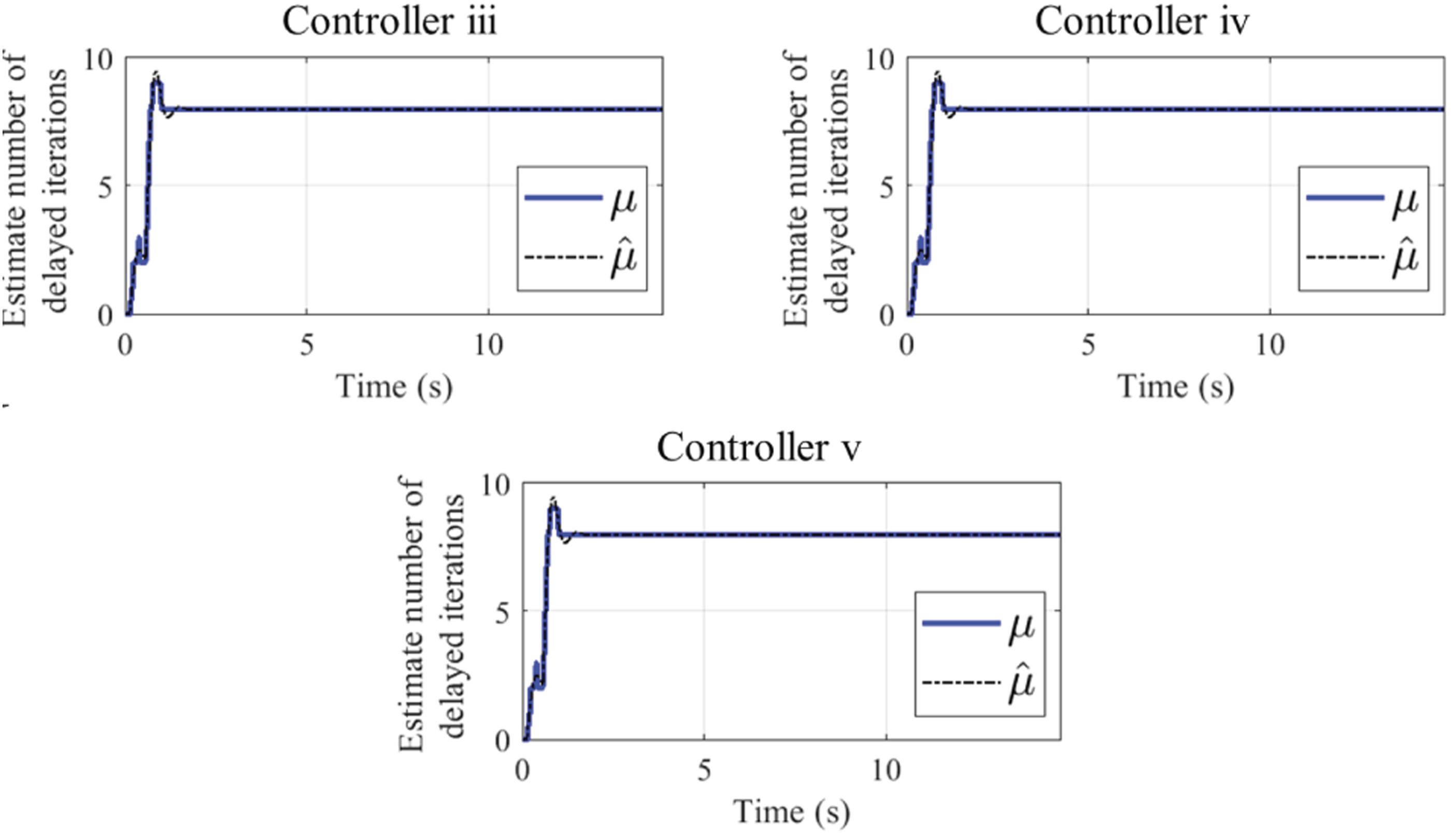
Figure 6 (left) shows the main states for the case m = 4 kg, and although controllers i and ii are theoretically stable without any actuator delay as discussed in Tajdari et al. (2020a), they cannot control the robot in presence of the time-delay (cyan and purple line) due to the singularity of the robots dynamic (resulted from the instability of pair Controlled case performance through the ADAMS model where m = 4 kg. Main states Online estimated w
Q
and w
R
, where m = 4 kg. Controller iv (left). Controller v (right). Online estimated of μ in the simulation case, where m = 4 kg. Accumulative absolute percentage error (E
ac
) report through the ADAMS model for the simulation case and through the fabricated robot for the experimental case.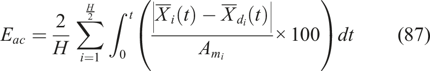
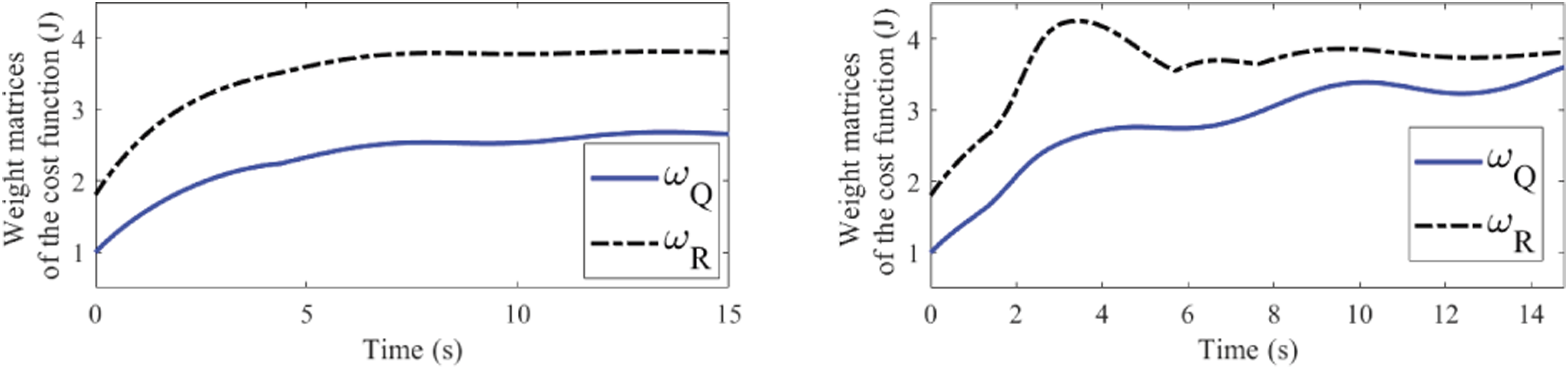
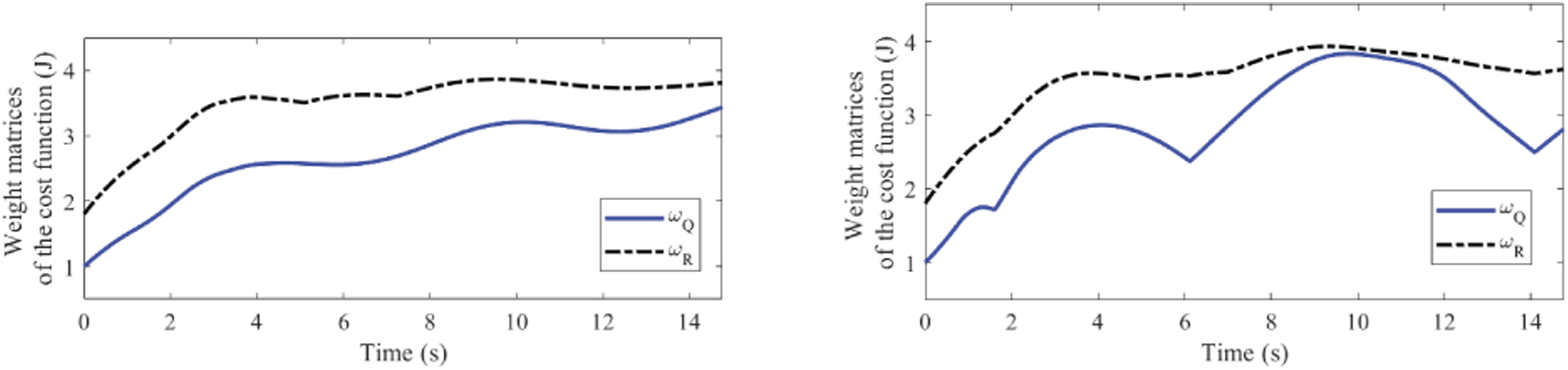
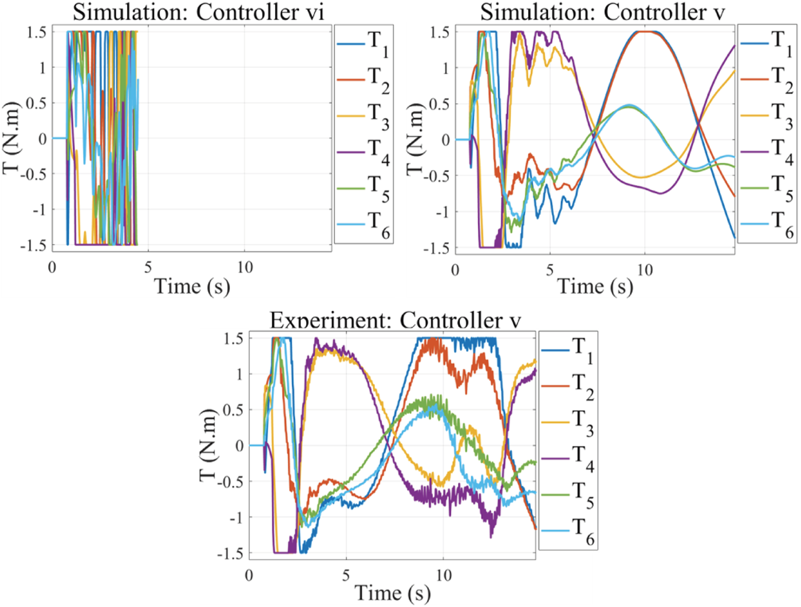
In comparison, Figure 9 displays the torques that have been applied to the device for the three time-delay controllers iii, iv, and v. Comparing the torques in Figure 9(left, and bottom) with Figure 9(right), the control effort generated by controllers iii and v are reduced by the time as the errors are decreasing. Also, the controllers’ torques have more trembling (from t = 0(s) till t = 5(s)) compared to controller iv that resulted from more sensitivity of the integral states to the tracking error due to (50), while the amplitude of the control signals generated by controller iv is increasing due to considerable tracking error. Regarding the figure, no saturation is observed due to the end-effector light mass selection as m = 4 kg. However, in practical applications, saturation may accrue. Thus, two more simulation experiments were performed via controllers v and vi where m = 5 kg to study the impact of the anti-windup scheme, as shown in Figure 10. Accordingly, controller vi (purple line) shows unstable performance and made the system to be stopped around t = 4(s) as the states passed the allowed work-space domain. In contrary, the controller v reveals a stable performance by converging the controller's and estimator's parameters in Figure 11(left) and 8 and reducing tracking error by the time. Regarding the controller v, the torques are saturated for a while depicted in Figure 13(right) specifically from t=0(s) till t=5(s). Motor torques in the simulation case, where m = 4 kg. Controlled case performance where m = 5 kg. Main states Online estimated w
Q
and w
R
with controller v, where m = 5 kg. Simulation case (left). Experiment case (right).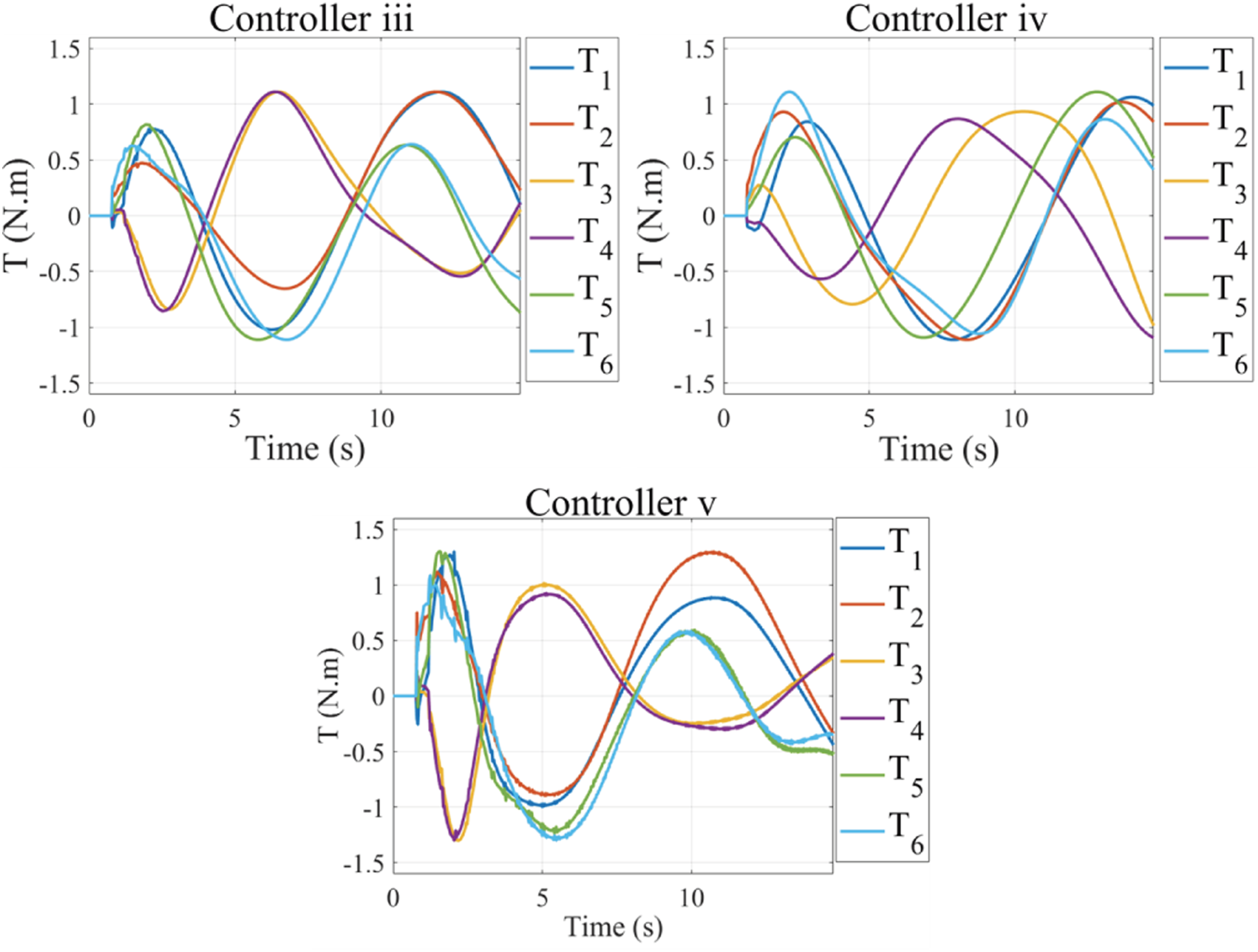
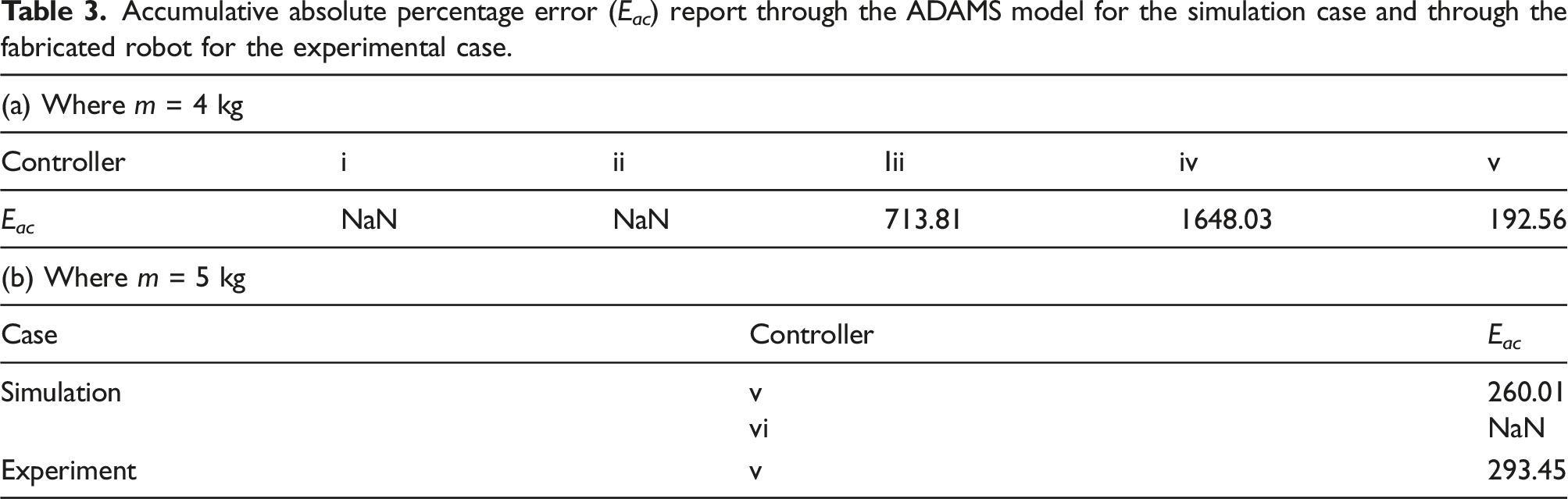
7.2. Experiment results
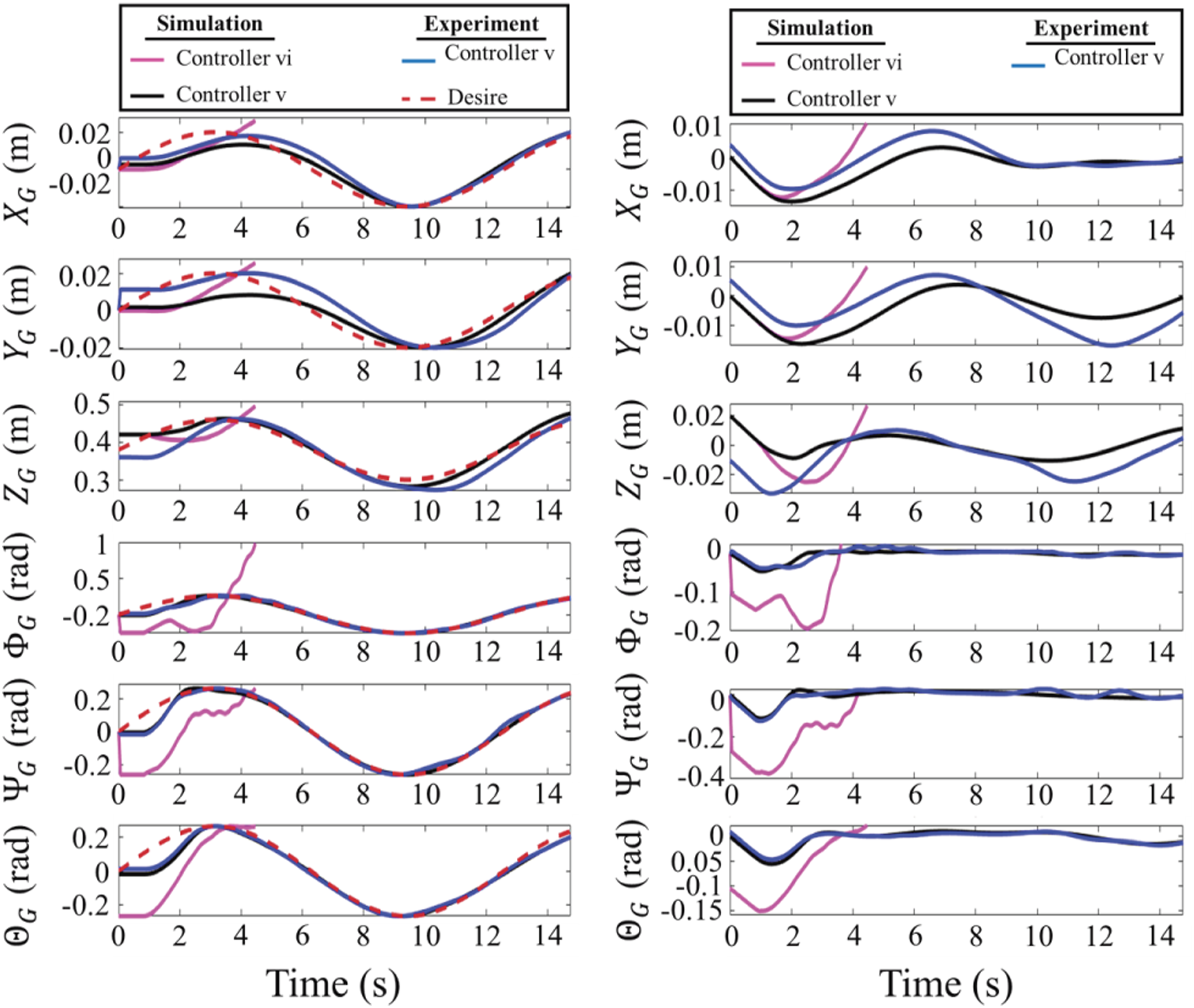
The controller v is applied on the robot introduced in the Experiment Setup section to verify and investigate the efficiency of the proposed controller in the case of actual disturbances and uncertainties. The same desire values in (86) are used to compare the simulation output. All other control parameters and initial conditions are assumed to be the same as the Simulation Results section, and m = 5 kg. In Figure 10(left), the controller performances in the main states are described. And comparing the effects of the controller v in simulation and experimental tests, Figure 10(right) reveals that the proposed controller is stable enough to sustain zero-error convergence in the face of natural uncertainties and disruptions. The output of the controllers is then defined separately based on the parameters in Table 3(b). According to the table, only the controller with the anti-windup scheme could keep the states in the allowed work-space and thus the controller vi failed due to the saturation accrued as in Figure 13(left). Regarding the table, the other controller v, for both cases of the simulation and experiments shows acceptable performance. Looking at the approximate w
Q
and w
R
trajectories in Figure 11, controller v has appropriate actions in both situations, and the output is more fluctuating in the experimental case as the ANN estimator attempts to resolve more uncertainties, that is, resolution of sensors, unpredictable internal time-delays, and natural disruptions. In addition, the estimated time-delay depicted in Figure 12(b) is different from a motor to another motor contrary to the simulation results in Figure 12(a), although the same time-delay value is manually manipulated for the servo motors. This may happen because of the sensor lag and other unknown delays of the motor gearbox, etc. Accordingly, although the torques in Figure 13 (bottom) are saturated for several time intervals, especially for T1, the controller shows stable and zero-error convergence thanks to the well-designed estimator and the anti-windup scheme. Online estimated of μ using controller v, where m = 5 kg: (a) simulation case and (b) experiment case per each motor. Motor torques, where m = 5 kg.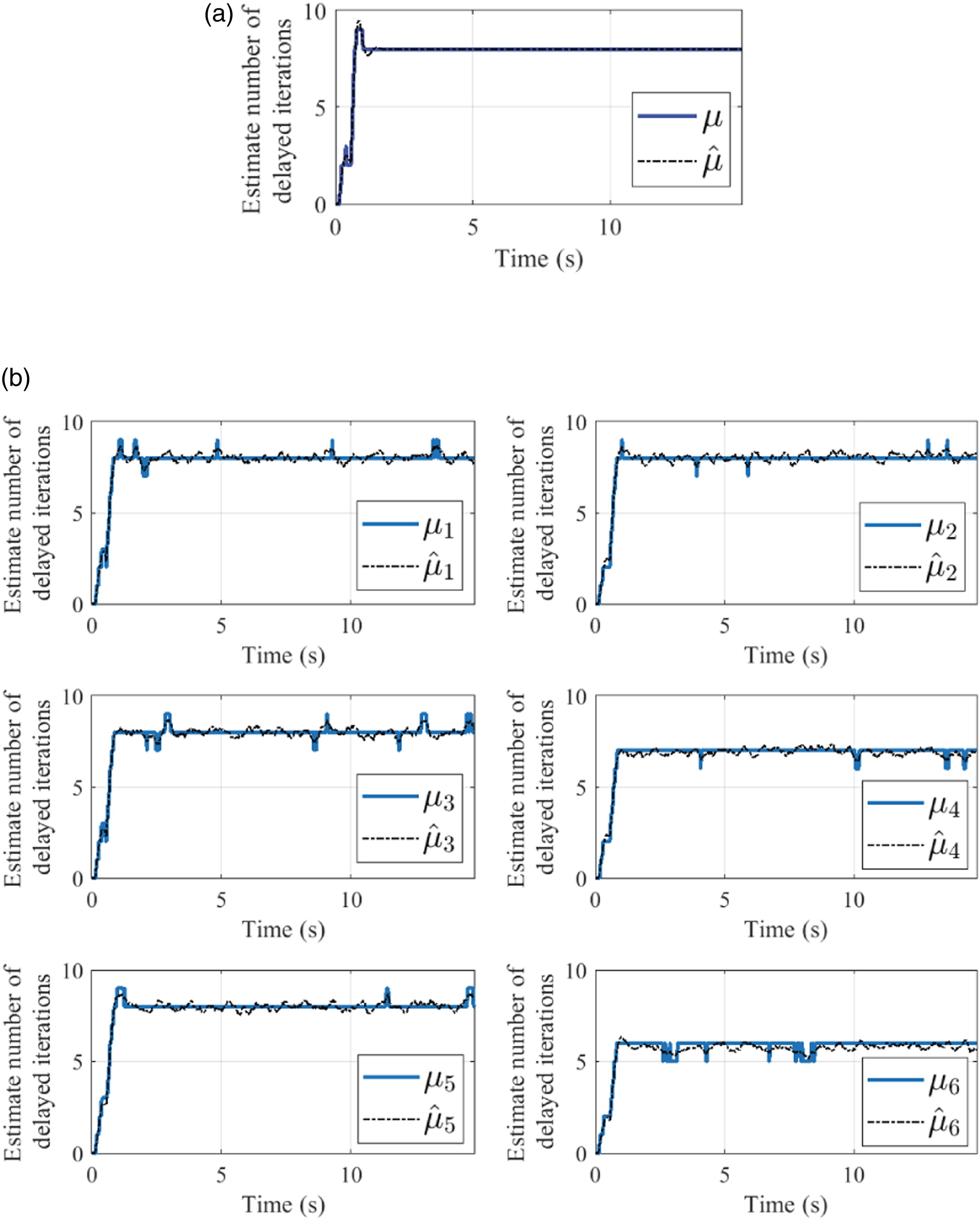
8. Conclusion
This paper investigates a novel robust control methodology integrated with an innovative adaptive time-delay estimator for a Stewart parallel robot integrated with the delayed rotary actuator. To achieve the desired value of the end-effector states, the implemented robot dynamic in ADAMS software is controlled online through the intelligent time-delay tuning of the LQI controller’s parameter. The robustness, as well as the adaptive estimator scheme, that is, the ANN estimator, elaborates on easy practical implementation, without the need for lengthy and costly measurements of the dynamic parameters. Furthermore, the simulation outputs depicted that the proper time-delay LQI controller with an intelligent estimator outperformed the other compared methods to control the dynamics of the device and eliminate the error of controlling in presence of the disturbing dynamic forces and the huge delay of the actuators in the ADAMS model. According to the validation of the controller through practical implementation of the controller on a fabricated robot, the perfect tracking was achieved and the TDE was successful. Further improvements contain designing an adaptive estimator with self-tuning the growth ratio of the adaptation rule emphasizing a more automated framework. In addition, a more complex robot platform will be discussed by mounting a second Stewart robot on the end-effector of the discussed robot in this paper which may challenge the proposed controller.
Footnotes
Declaration of conflicting interests
The author(s) declared no potential conflicts of interest with respect to the research, authorship, and/or publication of this article.
Funding
The author(s) disclosed receipt of the following financial support for the research, authorship, and/or publication of this article: This work is partly supported by Dutch NWO Next UPPS—Integrated design methodology for Ultra Personalised Products and Services project under Grant 15470.