
Abstract
Wheel-rail impact, which arises from structural discontinuities and short-wave defects, becomes more serious with higher train speeds and larger axle loads. The large impact load can accelerate the deterioration of vehicle-track components and induce a high level of impact noise. This paper aims to better understand the characteristics of wheel-rail impact and redevelop corresponding mitigation measures. First, a well-validated vehicle-track vertical interaction model with a singular rail defect is built up considering nonlinear Hertz contact. Then, the simulated wheel-rail impact force is characterized in both the time and frequency domains with different running speeds and defect geometries employing continuous wavelet transform. The identified characteristic frequencies are correlated to the track resonance modes. Afterward, a parameter sensitivity analysis of railpads, ballast, roadbed, and suspensions is performed to obtain the mitigation measures of wheel-rail impact. The results show that the wheel-rail impact force can be characterized by four stages in the time domain, the quasi-static stage before the impact, the forced vibration, the free vibration, and the quasi-static stage after the impact, respectively. Four characteristic frequencies are identified in the wheel-rail impact response: f1 at 45 Hz, f2 at 100 Hz, f3 at 260 Hz, and f4 at 810 Hz. Among them, f4 has the dominant vibration energy and is determined together by the pinned-pinned resonance mode and the defect excitation frequency. Characteristic frequencies f1, f2, and f3 correspond to the ballast, sleeper, and rail resonance modes, respectively, which are independent of the defect geometry. The increase of railpad stiffness can effectively reduce the maximum wheel-rail impact force and thus the impact factor. Larger railpad stiffness and damping can significantly reduce the dominant vibration energy at about 810 Hz of f4. This work can contribute to the optimization of vehicle-track parameters for a new design of more impact-resistant railways.
Keywords
1. Introduction
Railway transport has become increasingly popular worldwide because it is safer, more economical, and environmentally friendly. In recent years, the railway has been improved with higher train speeds and larger axle loads. With these two trends, wheel-rail impact, which arises from structural discontinuities (rail joints (Yang et al., 2021) and crossings (Xu and Liu, 2021)) and short-wave rail and wheel defects (flats (Bian et al., 2013), squat (Deng et al., 2019), and scratches (Jin et al., 2004)), has become a more serious problem. Wheel-rail impact leads to a large contact force and fierce vibration, accelerating the deterioration of vehicle-track components and increasing the maintenance cost. Besides, the resulting high level of impact noise is complained about by passengers and residents near the railway lines. Therefore, it is important to understand the characteristics of wheel-rail impact and develop the corresponding mitigation measures.
Many theoretical and experimental types of research have been conducted to investigate the wheel-rail impact. Jenkins et al., 1974 first characterized the wheel-rail impact load at dipped joints as P1 force and P2 force. Zhai and Sun, 1994 developed a detailed vehicle-track vertical interaction model and analyzed the influence of the running speed and the unsprung mass on P1 and P2 forces at a dipped joint. It is found that P1 and P2 forces significantly increase with a higher speed and a larger unsprung mass. Zhao et al., 2014 studied the wheel-rail impact at rail squats and reported that the railpad modeling and parameters play a significant role in the high-frequency vehicle-track interaction. They suggested carefully examining the service state of the railpads to determine an appropriate railpad model and parameters for reliable predictions.
To more accurately simulate the wheel-rail impact, Wu and Thompson, 2004 studied the effects of track nonlinearity on the wheel-rail impact, by including the nonlinear properties of railpads and the ballast in the track model. It is found that the impact force and track vibration using the nonlinear track model are noticeably higher than those of the linear track model. Dukkipati and Dong, 1999 improved the rail model with the Timoshenko beam instead of the Euler beam and achieved a better agreement with the measurement results in terms of P1 force. Baeza et al., 2008 applied the flexible wheelset model instead of the rigid wheel model and reported that the flexible wheelset model slightly reduces the simulated wheel-rail impact force. (Liu et al., 2022), A. Prasad and Jafferson, 2021 and Zhao et al., 2014 employed three-dimensional (3D) finite element (FE) vehicle-track models to simulate wheel-rail impact at rail spalling, wheel flats, and squats, respectively. Compared to the multi-rigid-body model used in Wanming, 2007; Zhao et al., 2019, the 3D FE vehicle-track model is much more time-consuming despite the higher accuracy in simulating high-frequency wheel-rail dynamic interaction. To validate the simulation results and better understand the wheel-rail impact characteristics, the field measurements of the wheel-rail contact force (Bi et al., 2020; Nielsen, 2008), axle box acceleration (Molodova et al., 2016), and rail acceleration (Yang et al., 2018) have been performed.
Despite the extensive research in the literature, it is found that most work mainly analyzes the wheel-rail impact responses in the time domain. However, the characteristics of wheel-rail impact in the frequency or time-frequency domains have not been fully identified. Furthermore, the systematic study of mitigation approaches to wheel-rail impact, especially considering the frequency-domain responses, has not been proposed.
This paper aims to better understand the characteristics of wheel-rail impact and develop the corresponding mitigation measures. For this purpose, a vehicle-track vertical interaction model at a singular rail defect is built up considering nonlinear Hertz contact. This model has been validated against the measurement and is widely used to analyze the wheel-rail dynamic forces and investigate the vibration of the vehicle-track coupled system (Wanming, 2007). The continuous wavelet transform is employed to analyze the simulated wheel-rail impact force in the time-frequency domain. A sensitivity analysis of vehicle-track parameters is performed to determine appropriate parameters for wheel-rail impact mitigation. The structure of this paper is as follows. Section 2 introduces the vertical vehicle-track interaction model. Section 3 characterizes the wheel-rail contact force in both the time and frequency domains and correlates the characteristic frequencies to track resonance modes. Section 4 performs the parameter sensitivity analysis of railpads, ballast, roadbed, and suspension systems and develops the mitigation measures of wheel-rail impact. The main conclusions are drawn in Section 5. This paper can contribute to the new design of railway lines with better impact resistance by optimization of vehicle-track parameters.
2. Vehicle-track interaction model
Figure 1 shows a typical vehicle-track vertical interaction model, which has been comprehensively validated against field data (Wanming, 2007). The notations in this figure are listed in Table 1. The vehicle sub-system considers the half of a railway passenger car and is modeled as a multi-rigid-body system with 10 degrees of freedom, including the bounce (Zc, Zt1 Zt2) and pitch (βc, βt1, βt2) of the car body, the front, and rear bogies, and the bounce (Z
wi
, j = 1∼4) of the four wheels. The simplified half-vehicle model does not consider the moment exerted by the car body weight. The track sub-system simulates the traditional ballast track and is represented as a three-layer discretely supported model. The rail is modeled by Euler beam elements which can accurately simulate rail vibration within 1500 Hz (Yang et al., 2018), generally covering the frequency of interest in this work. The sleepers are modeled by mass elements. The railpad and roadbed are modeled by discrete spring-damper elements. The ballast model considers both the oscillating mass of the ballast block and its elasticity. Vehicle-track vertical interaction model. Notations and parameters in the vehicle-track vertical interaction model (Wanming, 2007).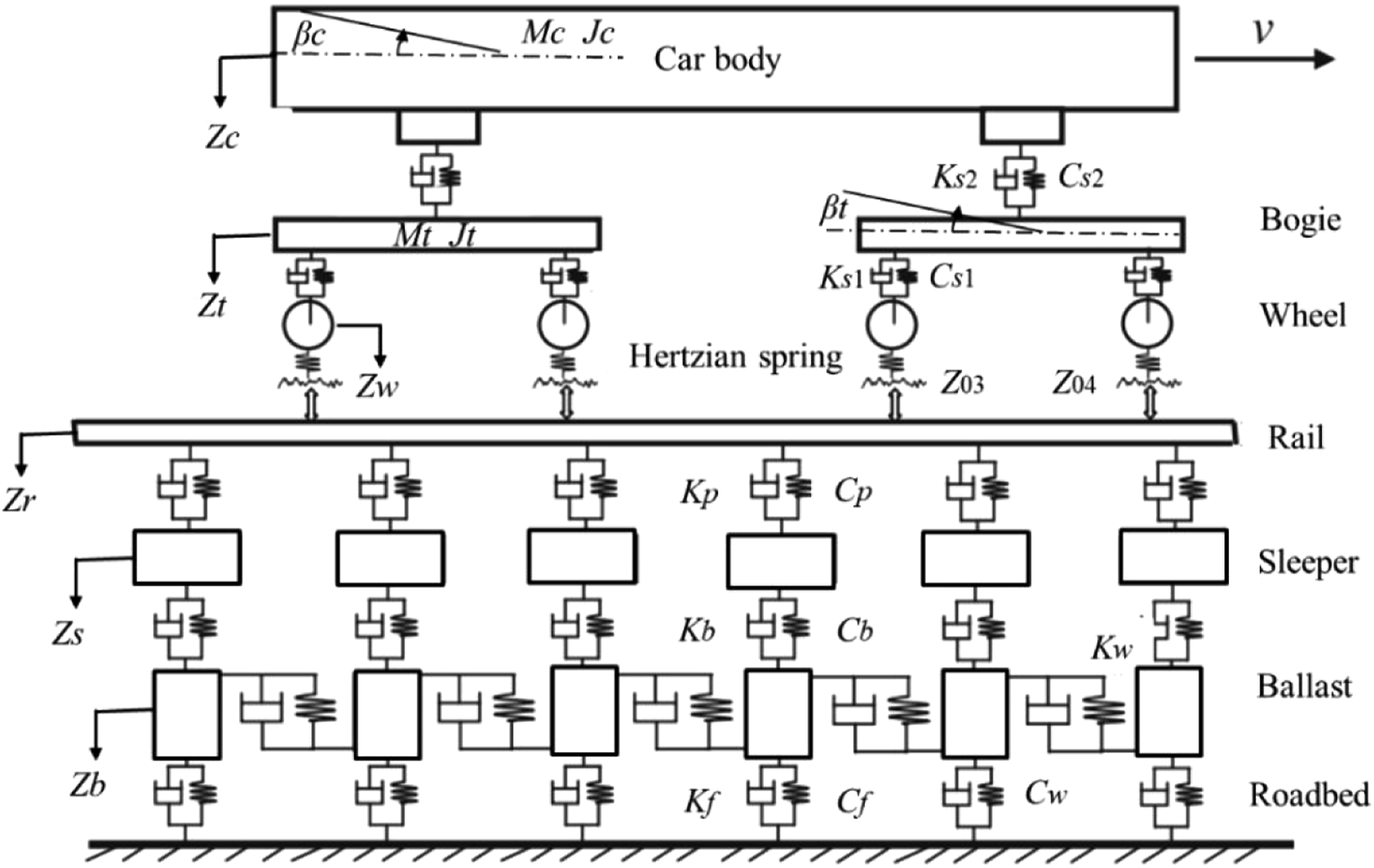
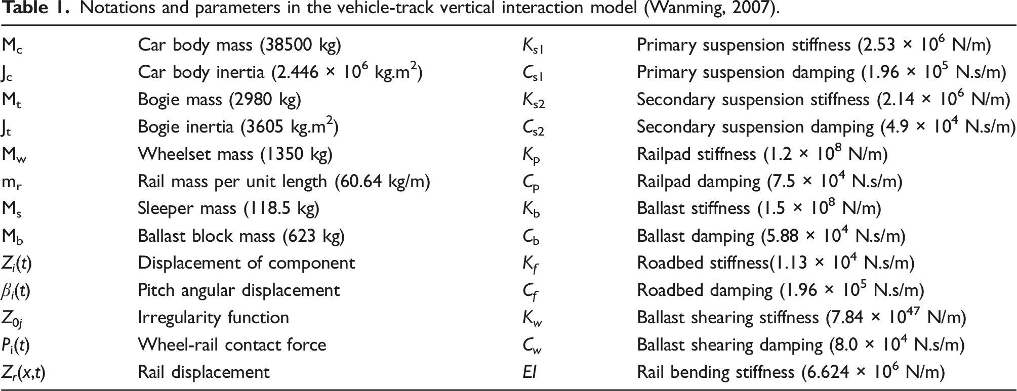
The vehicle sub-system and track sub-system are coupled at the wheel-rail interface by Hertzian nonlinear elastic theory. The vertical wheel-rail contact force at the jth wheel is calculated as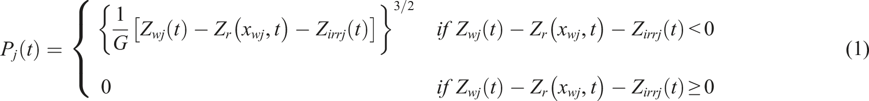
Without loss of generality, the motion equations of the vehicle-track coupled system can be formulated as follows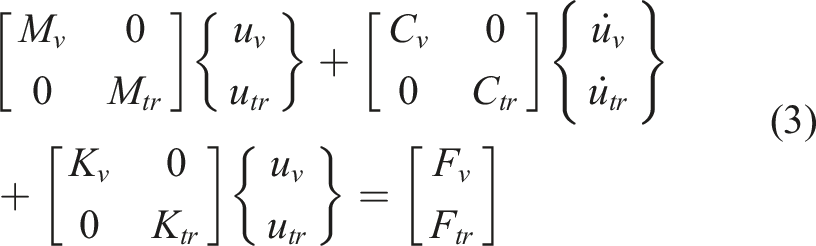
3. Characterization of the wheel-rail impact responses
3.1. Wheel-rail impact force in the time domain
Figure 2 shows the calculated wheel-rail impact force at wheel 1 in the time domain. In this case, the running speed is 100 km/h. The depth and width of the defect are 0.1 mm and 40 mm, respectively, which is the size of a typical singular rail defect, such as a rail squat or scratch (Deng et al., 2019; Jin et al., 2004). At t0 = 3 s, wheel 1 starts to pass the rail defect. Afterward, the impact force response is taken from wheel 1 by default. We can see from Figure 2 that the impact force response can be approximately divided into four parts, indicated by red dashed lines. Before 3 s, the wheel-rail coupled system is in a quasi-static contact state, and the quasi-static load (Psta) is 110 kN. From 3 s to 3.0015 s, the wheel-rail coupled system is in a forced vibration state excited by the defect geometry, with a local valley at 3.0004 s and a local peak at 3.0009 s. Between 3.0015 s and 3.015 s, the wheel-rail coupled system is in a free vibration state with gradual attenuation of the impact force. After 3.015 s, the system returns to a quasi-static state and the contact force is equal to the quasi-static load of 110 kN. The wheel-rail impact force at wheel 1 in the time domain.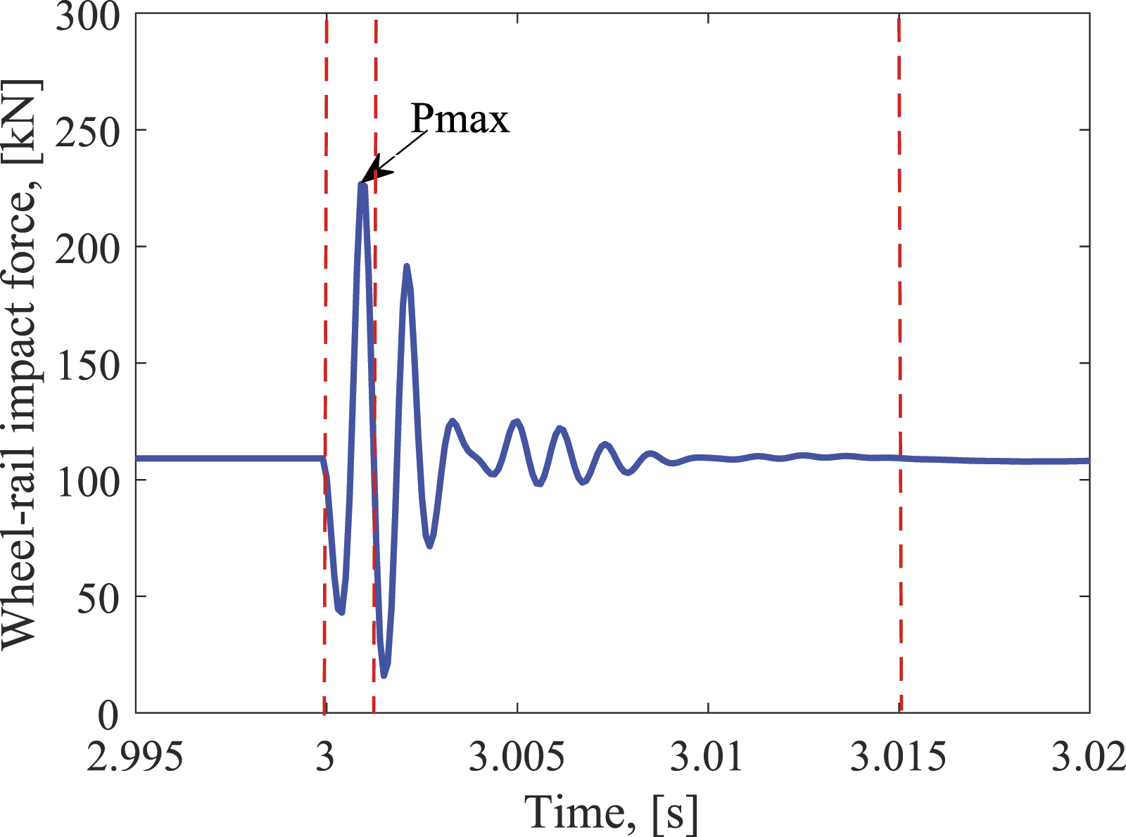
The maximum wheel-rail impact force (Pmax in Figure 2) is 227 kN. In the literature, the dynamic amplification factor or impact factor is defined as the quotient of the maximum wheel load and the static load (Pmax/Psta) to describe the maximum acceptable wheel load. In this case, the impact factor is approximately 2.0. Since the impact factor is taken as an important indicator for the new track design, the effective reduction of maximum wheel-rail impact force is necessary. Figure 3 shows the influence of the running speed and rail defect depths on the maximum wheel-rail impact force Pmax. It can be seen that Pmax almost linearly increases with increasing speeds and depths. Therefore, for the new design of higher-speed lines, the impact factor may exceed the acceptable limit using the current vehicle-track parameters. The corresponding mitigation measures of the wheel-rail impact force need to be developed. In addition, for the existing lines, the rail defect geometry needs to be properly maintained, for instance, by grinding, to keep the impact factor within the limit and increase the service life of the vehicle-track components. The maximum wheel-rail impact force with (a) different speeds and (b) rail defect depths.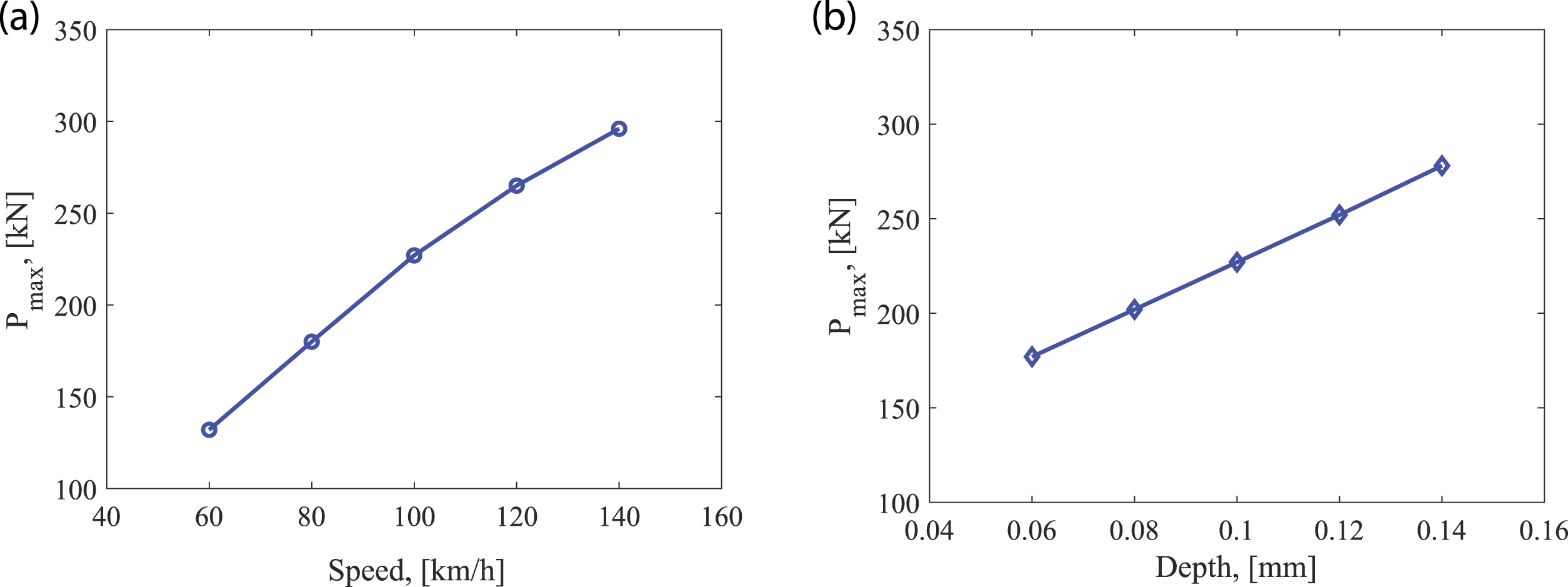
3.2. Wheel-rail impact force in the time-frequency domain
The wheel-rail impact signal is nonstationary and contains many frequency components. To process this type of signal, we employ the continuous wavelet transform (CWT), which can decompose the signal in both the time and frequency domains with high resolution. For other time-frequency techniques, the short-time Fourier transform (STFT) uses a fixed window size, and thus, a trade-off must be made between time and frequency resolutions. The Wigner–Ville distribution (WVD) can provide a high resolution of the time-frequency representation, but it is subjected to the interference of cross-term (Yang et al., 2019). In the CWT, the convolutions of the analyzed signal are calculated with a group of scaled and shifted wavelet functions. The wavelet coefficients W
n
(s) of the analyzed signal x
n
can be represented as follows (Vetterli and Kovacevic, 1995)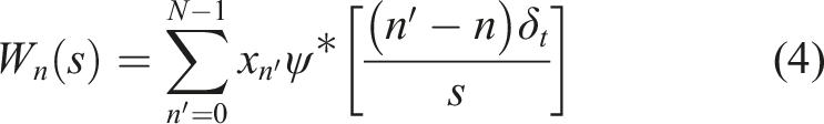
Figure 4(a) shows the WPS of wheel-rail impact force. The color contrast in this figure indicates the amount of vibration energy concentrated in a frequency range (the vertical axis) at a particular time (the horizontal axis). It can be seen that the major impact energy of the wheel-rail system concentrates on a broad frequency range of about 630–1100 Hz, marked by the white dashed box in Figure 4(a). This impact signal attenuates rapidly and can hardly be observed after 3.003 s. Figure 4(b) shows the local WPS at 3.001 s, indicated by the vertical monk line in Figure 4(a). Four characteristic frequencies of the wheel-rail impact force are identified, and they are f1 at 45 Hz, f2 at 100 Hz, f3 at 260 Hz, and f4 at 810 Hz, respectively. Among them, the vibration energy of f4 is dominant, agreeing with the observation in Figure 4(a). The wavelet power spectrum (WPS) of the wheel-rail impact force. (a) WPS. The white dashed box marks the major wheel-rail impact energy, and the monk line indicates the local WPS at time 3.001 s (b) WPS at time 3.001 s f1, f2, f3, f4 indicate the four characteristic frequencies of the wheel-rail impact force.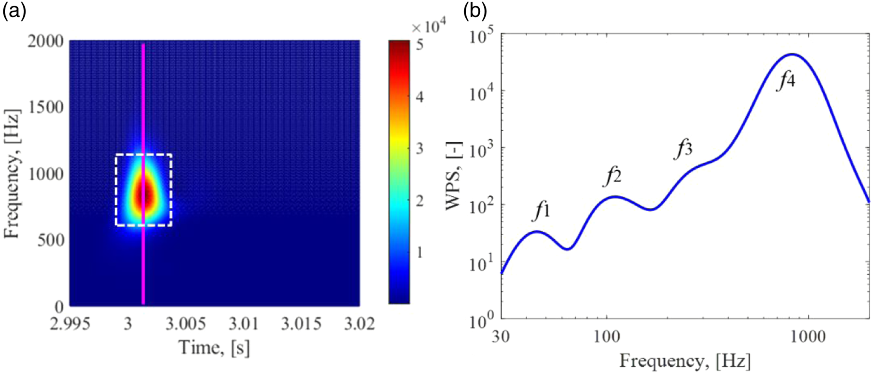
To understand the physical phenomena of these four characteristic frequencies, the track receptance is obtained, as shown in Figure 5. Track receptance presents the track displacement at each frequency per unit force, and its peaks or dips correspond to the resonance or anti-resonance modes of track structures (Grassie et al., 1982; Thompson, 1993). It can be seen from Figure 5 that four peaks are observed in the receptance function, indicated by r1, r2, r3, r4. Figure 1 shows that the current track model is a three-layer discretely supported model, including the rail, sleepers, and ballast blocks, connecting by springs and dampers. We perform modal analysis and find that peak r1 at 55 Hz corresponds to the ballast resonance mode, which is dominated by the ballast block mass and roadbed stiffness. Peak r2 at 160 Hz corresponds to the sleeper resonance mode, which is mainly determined by the sleeper mass, ballast stiffness, and railpad stiffness. Peak r3 at 336 Hz corresponds to the rail resonance mode, for which the rail mass and railpad stiffness are the major contributors. Peak r4 at 1070 Hz corresponds to the pinned-pinned resonance mode, which is a vertical bending mode with a wavelength of twice sleeper span. Track receptance. r1, r2, r3, r4 indicate four track resonance modes.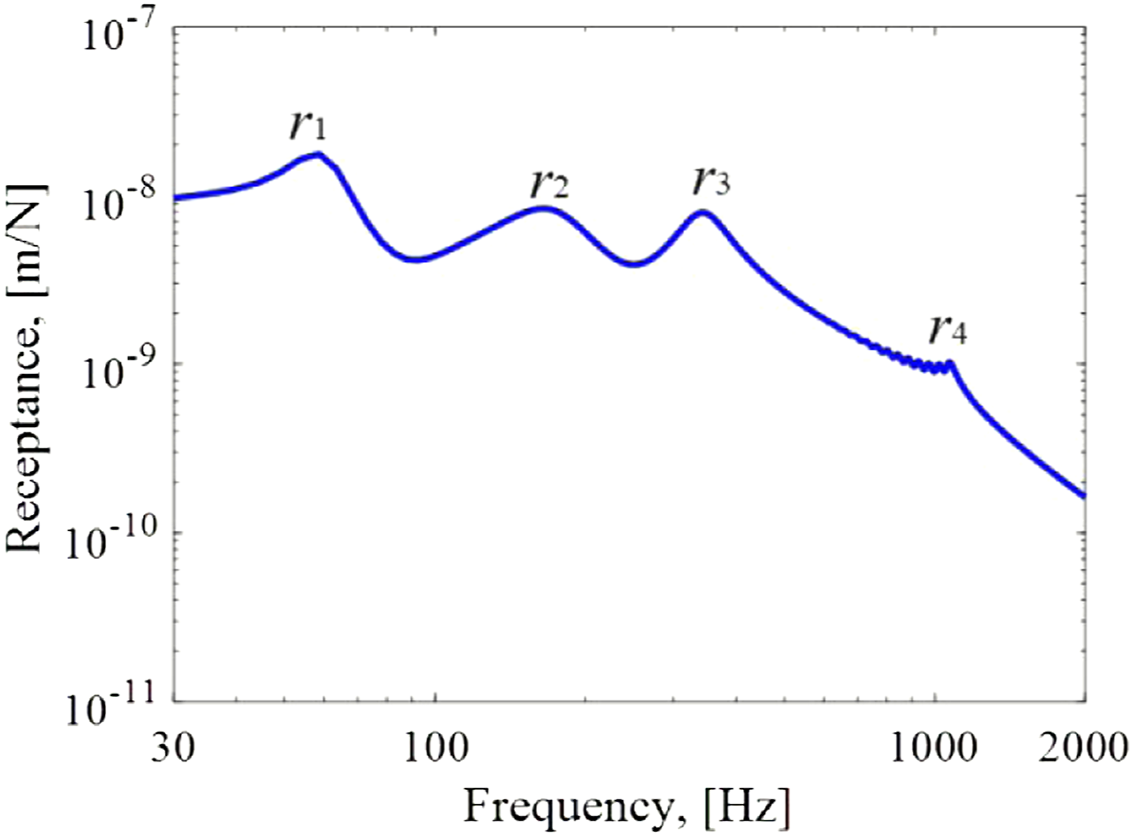
Compared to Figure 4b and Figure 5, it is clear that the characteristic frequencies f1, f2, f3, f4 of wheel-rail impact force should be correlated to the four track resonance modes, r1, r2, r3, r4, which are ballast, sleeper, rail, and pinned-pinned resonance modes. It is noted that frequencies of f1, f2, f3, f4 is smaller than those of r1, r2, r3, r4, which is possibly caused by the unsprung mass from the vehicle system that adds the vibration mass of the track system and reduces the mode frequencies (Grassie et al., 1982; Thompson, 2009). The excitation frequency from the rail defect is 695 Hz, calculated by v/L, where v is the running speed and L is the defect width. The pinned-pinned resonance (1070 Hz) could be excited due to the wheel-rail impact. The defect excitation frequency and the track’s natural pinned-pinned mode together cause the wheel-rail impact energy to concentrate on the frequency range of 630–1100 Hz with a peak at f4.
Figure 6 shows the characteristic frequencies of the wheel-rail impact force with different rail defect widths. It is found that f1, f2, f3 are independent of the defect width, indicating they are the eigenfrequencies of the vehicle-track coupled system, which are determined by the vehicle-track parameters. In contrast, f4 increases with the smaller defect width, corresponding to the higher excitation frequency. This result indicates that f4 is determined together by the eigenfrequency of the vehicle-track coupled system (pinned-pinned resonance mode in this case) and the excitation frequency. The influence of the rail defect width on wheel-rail impact characteristic frequencies.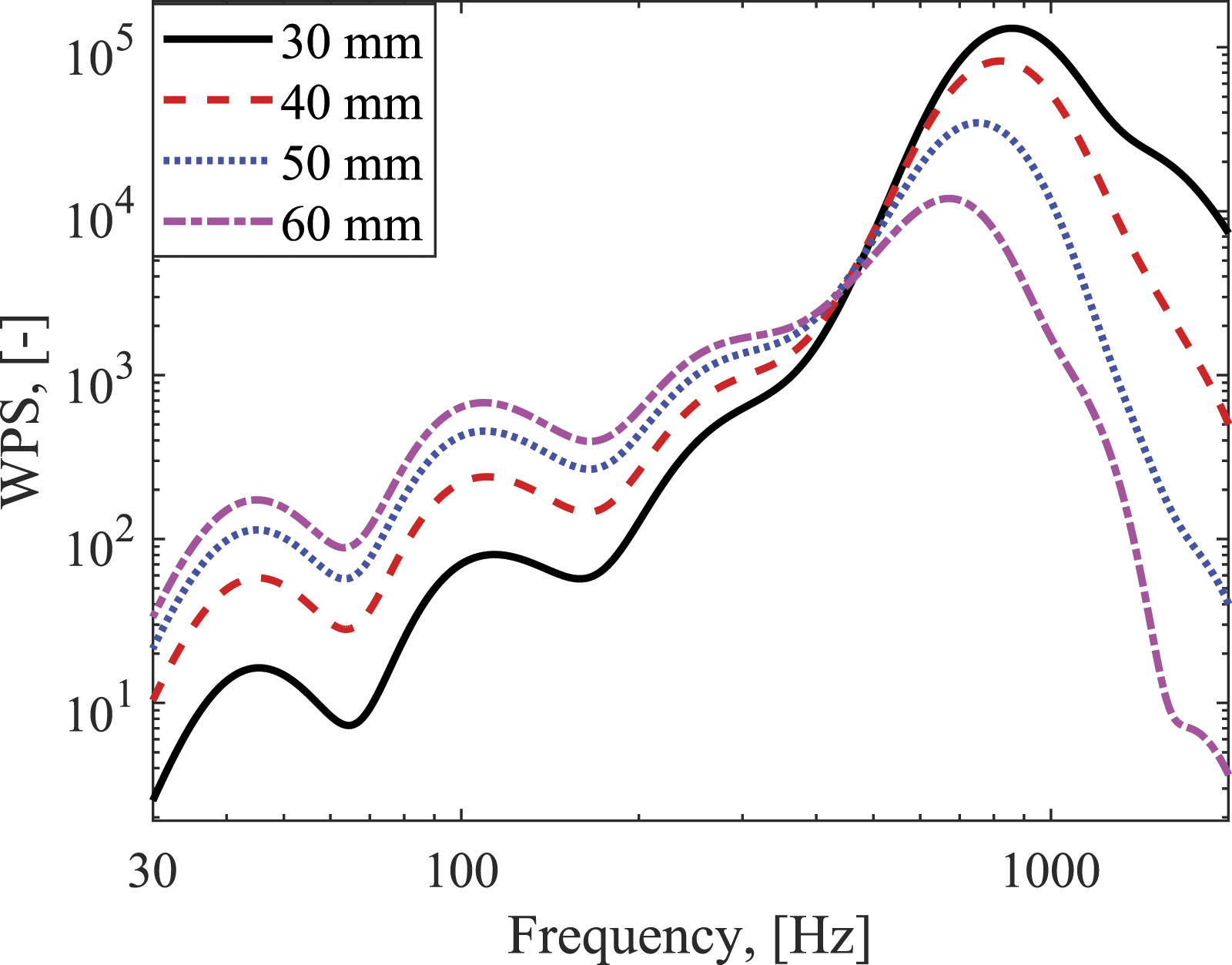
4. Sensitivity analysis of vehicle-track parameters for mitigation of wheel-rail impact
To develop the mitigation measures of the wheel-rail impact, we perform a sensitivity analysis of dynamic parameters of elastic components in the vehicle-track coupled system, including the railpads, ballast, roadbed, and suspension systems. In the sensitivity analysis, the stiffness and damping of these elastic components are scaled to their 1/3 or 3 times, and their influences on the wheel-rail impact force in both the time and frequency domains are analyzed.
4.1. The influence of railpad parameters
Figure 7 shows the wheel-rail impact force at a singular rail defect with different railpad stiffness values. It can be seen from Figure 7(a) that the maximum impact load significantly decreases from 226 kN to 183 kN when the railpad stiffness becomes three times larger, but increases to 248 kN when the railpad stiffness is reduced to its one third. Therefore, for the new design of tracks, the relatively stiffer railpad should be used to mitigate the maximum wheel-rail impact force, which can extend the service time of the railway components and reduce the maintenance cost. The influence of railpad stiffness on the wheel-rail impact force in the time and frequency domains. (a) Time domain; (b) frequency domain.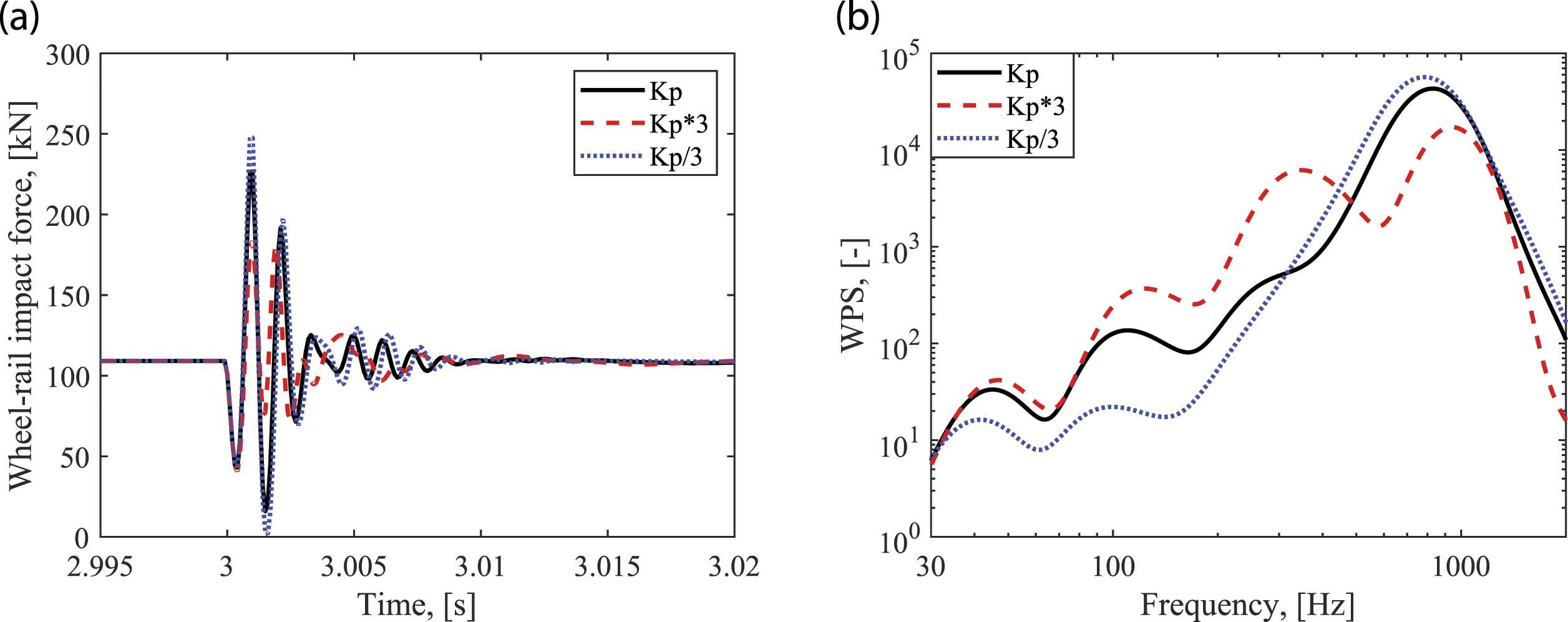
Figure 7(b) shows the influence of the railpad stiffness on wheel-rail impact force in the frequency domain. It can be seen that the four characteristic frequencies f1, f2, f3, f4 are all shifted to higher frequencies with the three times larger railpad stiffness. Their increments are 2 Hz, 17 Hz, 77 Hz, and 123 Hz, respectively, indicating f3, f4 corresponding to the rail and pinned-pinned resonance modes are more sensitive to the railpad stiffness variations than those of sleeper and ballast resonance modes f1, f2. Further, the dominant vibration energy at f4 is considerably reduced to around 1/3 when the railpad stiffness increases three times. Meantime, the vibration energy at the other three characteristic frequencies increases, especially at f3 which becomes more pronounced. When the railpad stiffness is reduced to one-third, the opposite trend is observed: the dominant vibration energy at f4 increases; characteristic frequencies f1, f2, f4 are shifted to lower frequencies; and the peak at f3 becomes so less pronounced that cannot be observed in the figure.
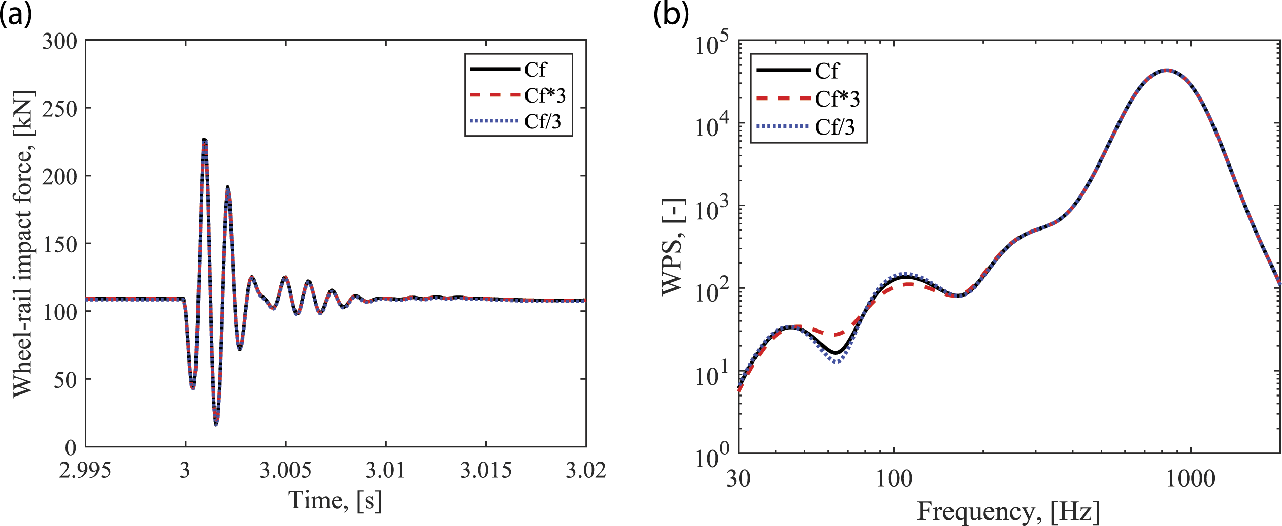
Figure 8 shows the influence of railpad damping on the wheel-rail impact force in the time and frequency domains. We can see from Figure 8(a) that the fluctuation of the impact force attenuates much slower and does not return to quasi-static load even at 3.02 s when the railpad damping becomes 1/3 smaller. This fluctuation force may cause differential wear and plastic deformation at the rail surface, which gradually accumulate after multiple wheel passages, leading to the formation of short pitch rail corrugation (Jin et al., 2004; Wen et al., 2008). In contrast, with a larger railpad damping, the fluctuation of impact force attenuates rapidly within 5 ms (e.g., from 3 s to 3.005 s). In addition, it is observed that the wheel-rail impact force between 3 s and 3.0015 s, including the maximum impact force slightly changes with different railpad damping values. Therefore, we can conclude that the railpad damping has an insignificant influence on the wheel-rail impact response in the forced vibration stage but significantly influences the impact attenuation in the free vibration stage. Figure 8(b) shows that the increase of railpad damping effectively reduces the vibration energy at the major frequency f4. The four characteristic frequencies are not changed by different railpad damping. The peak at f3, corresponding to the rail resonance mode, becomes more pronounced with a smaller railpad damping. The influence of railpad damping on the wheel-rail impact force in the time and frequency domains. (a) Time domain; (b) frequency domain.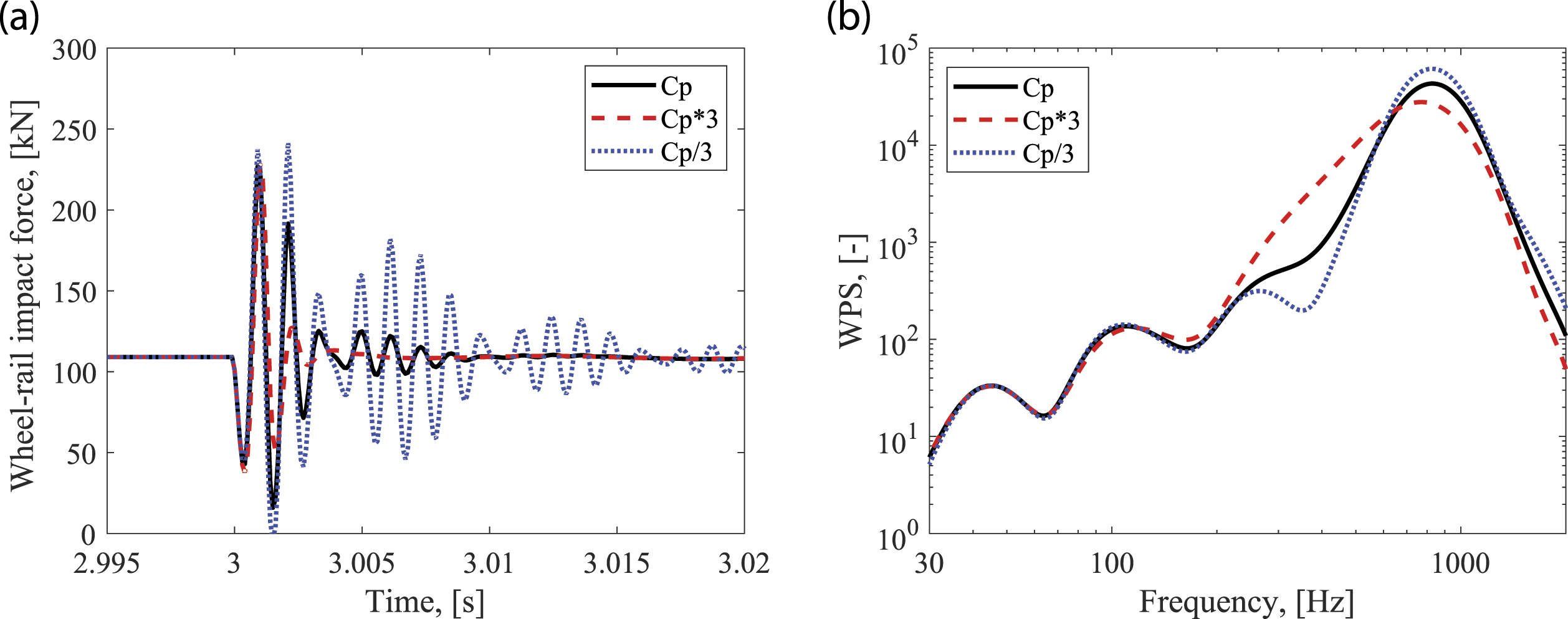
Overall, the increase of railpad stiffness can effectively reduce the maximum wheel-rail impact force, and thus the impact factor, which is an important indicator for the new design of tracks. Besides, the increase of railpad stiffness and damping can significantly reduce the dominant vibration energy at the frequency f4. The peak at f3, corresponding to the rail resonance mode, is the most sensitive to the railpad parameter variation.
4.2. The influence of ballast parameters
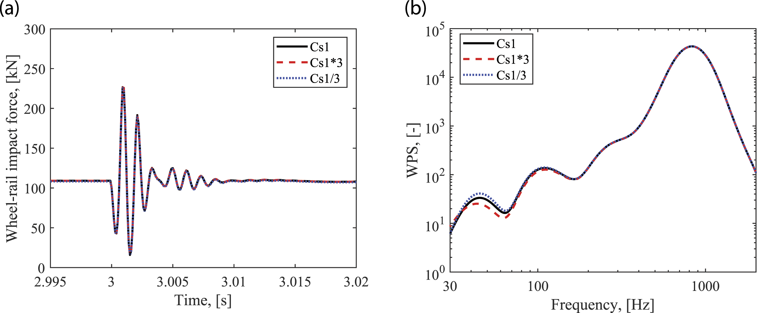
Figure 9 shows the influence of ballast stiffness on the wheel-rail impact force in the time and frequency domains. It can be seen from Figure 9(a) that the ballast stiffness has insignificant influences on the time-history of the impact force. Slight deviation between these three cases is observed at 3.003 s and 3.005 s. Figure 9(b) shows that the ballast stiffness does not influence the impact force at the major frequency of 820 Hz (f4), but mainly influence the energy distribution at lower frequencies below 400 Hz. Specifically, the larger ballast stiffness shifts the three characteristic frequencies f1, f2, f3 to the larger values and makes the sleeper resonance mode f2 more noticeable and rail resonance mode f3 less noticeable, and vice versa. Figure 10 shows the influence of ballast damping on the wheel-rail impact force. The ballast damping has a very slight effect on the time-history impact force but influences the frequency domain response between 100 Hz and 400 Hz. It is found that the smaller ballast damping makes the sleeper resonance mode f2 more noticeable and rail resonance mode f3 more pronounced. The influence of ballast stiffness on the wheel-rail impact force in the time and frequency domains. (a) Time domain; (b) frequency domain. The influence of ballast damping on the wheel-rail impact force in the time and frequency domains. (a) Time domain; (b) frequency domain.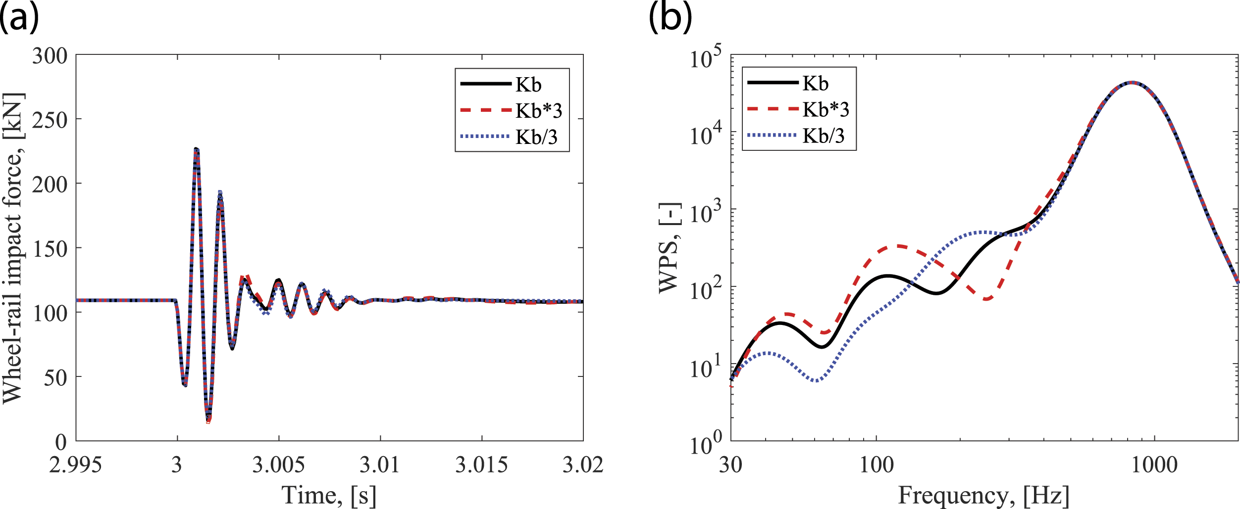
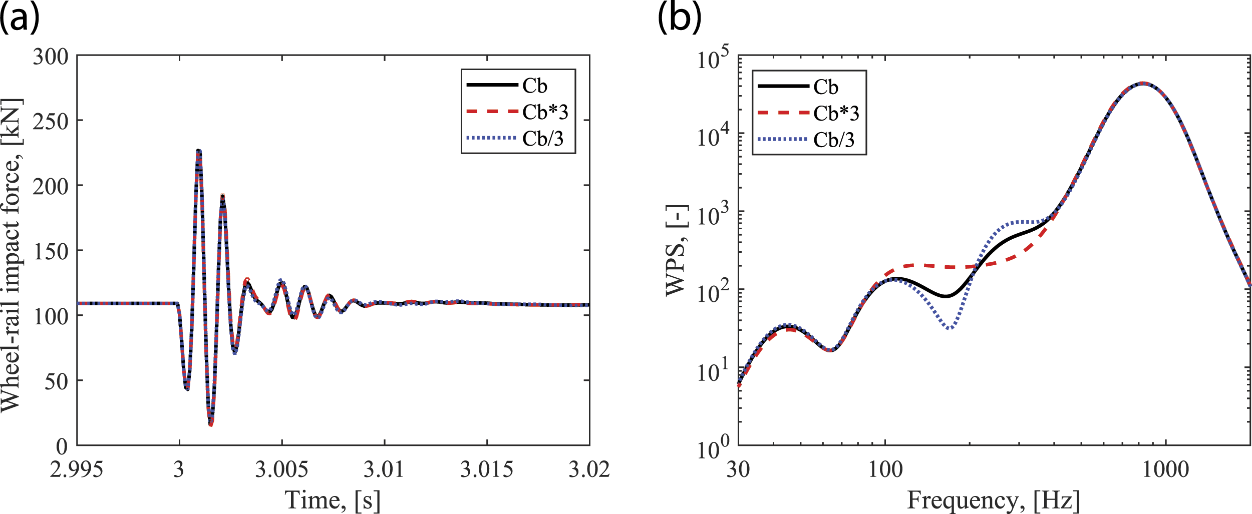
In summary, ballast parameters have an insignificant influence on the wheel-rail impact force in the time domain but can change the energy distribution in the frequency domain below 400 Hz. Especially, the larger ballast stiffness makes the sleeper resonance mode f2 more noticeable and rail resonance mode f3 less noticeable, while the larger ballast damping makes f2 and f3 both less pronounced.
4.3 The influence of roadbed parameters
The influence of roadbed stiffness on the wheel-rail impact force is shown in Figure 11. Figure 11(a) indicates the time-history of the impact force barely changes with different roadbed stiffness, despite the very slight deviation after 3.008 s. In the frequency domain (Figure 11(b)), we can see that the roadbed stiffness mainly influences the impact responses at a lower frequency than 200 Hz, the ballast resonance mode f1 and the sleeper resonance mode f2, and has negligible influence on those at the rail resonance mode f3 and the pinned-pinned resonance mode f4. Specifically, larger roadbed stiffness shifts the f1 and f2 to larger frequencies and makes the f1 more pronounced and f2 less pronounced. Figure 12 shows that the roadbed damping does not influence the wheel-rail impact force in the time domain but slightly change the magnitude of vibration energy in the frequency domain below 200 Hz. Overall, the roadbed parameters barely influence the wheel-rail impact force in the time domain and mainly change the energy distribution in the frequency domain below 200 Hz. The influence of roadbed stiffness on the wheel-rail impact force in the time and frequency domains. (a) Time domain; (b) frequency domain. The influence of roadbed damping on the wheel-rail impact force in the time and frequency domains. (a) Time domain; (b) frequency domain.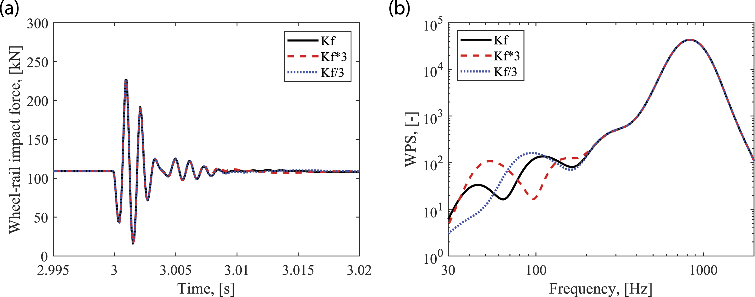
4.4. The influence of suspension parameters
Figure 13 and Figure 14 show the influence of primary suspension stiffness and damping on the wheel-rail impact force, respectively. It can be seen that primary suspension parameters overall do not affect the wheel-rail impact responses in the time domain and have a slight influence on the magnitude at ballast resonance f1 in the frequency domain. Besides, we analyze the influence of secondary suspension parameters, which also do not affect the wheel-rail impact responses. Therefore, it is concluded that the optimization of the vehicle suspension parameters does not contribute to the mitigation of wheel-rail impact at the singular rail defect applied in this work. The influence of primary suspension stiffness on the wheel-rail impact force in the time and frequency domains. (a) Time domain; (b) frequency domain. The influence of primary suspension damping on the wheel-rail impact force in the time and frequency domains. (a) Time domain; (b) frequency domain.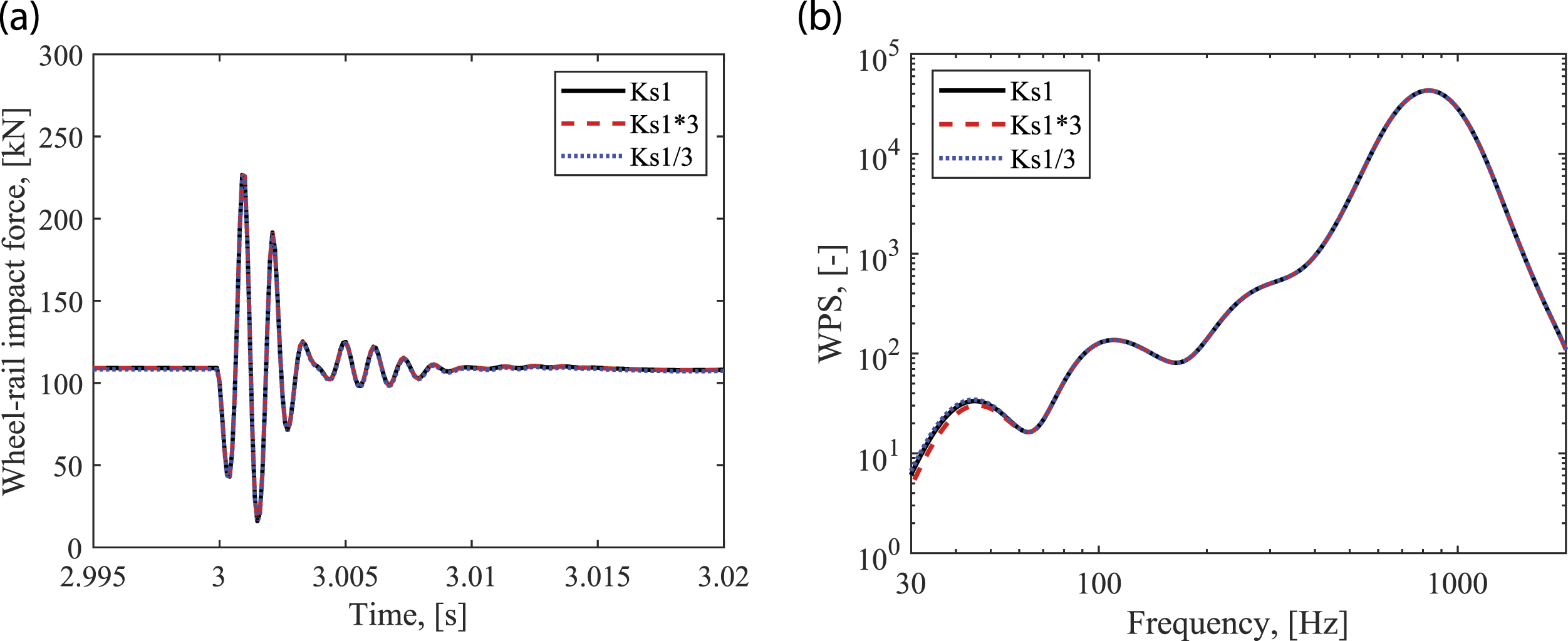
5. Conclusions
This paper investigates the characteristics and mitigation of the wheel-rail impact at a singular rail defect. A vehicle-track vertical interaction model is built up considering nonlinear Hertz contact. The wheel-rail impact force is characterized in both the time and frequency domains with different running speeds and defect geometries. A parameter sensitivity analysis of the vehicle-track system, including railpads, ballast, roadbed, and suspension systems, is performed to identify the mitigation measures of the wheel-rail impact. The main conclusions are drawn as follows: (1) The wheel-rail impact force is characterized in four stages in the time domain, the quasi-static stage before the impact, the forced vibration, the free vibration, and the quasi-static stage after the impact, respectively. (2) The maximum wheel-rail impact force almost linearly increases with larger speed and defect depth. (3) Four characteristic frequencies are identified in the wheel-rail impact response, f1 at 45 Hz, f2 at 100 Hz, f3 at 260 Hz, and f4 at 810 Hz, respectively. Among them, f4 is determined together by the pinned-pinned resonance mode and the defect excitation frequency and has the dominant vibration energy. f1, f2, f3 correspond to the ballast, sleeper, and rail resonance modes, respectively, which are independent of the defect geometry. (4) The increase of railpad stiffness can effectively reduce the maximum wheel-rail impact force, and thus the impact factor that is an important indicator for the new design of tracks. Larger railpad stiffness and damping can significantly reduce the dominant vibration energy at about 810 Hz of f4. (5) Ballast parameters have insignificant influence on the wheel-rail impact force in the time domain but can change the energy distribution in the frequency domain below 400 Hz. Specially, the larger ballast stiffness makes the sleeper resonance mode f2 more noticeable and rail resonance mode f3 less noticeable, while the larger ballast damping makes f2 and f3 both less pronounced. (6) Roadbed parameters barely influence the wheel-rail impact force in the time domain and mainly change the energy distribution in the frequency domain below 200 Hz. (7) The optimization of the vehicle suspension parameters does not contribute to the mitigation of wheel-rail impact at the singular rail defect applied in this work.
Overall, this paper contributes to a better understanding of the wheel-rail impact and a new design of new railways with more impact resistance. In future work, a more advanced model may be used to consider the moment exerted by the car body weight and the nonlinear properties of the railpads and ballast to achieve better simulation accuracy.
Footnotes
Declaration of Conflicting Interests
The author(s) declared no potential conflicts of interest with respect to the research, authorship, and/or publication of this article.
Funding
The author(s) received no financial support for the research, authorship, and/or publication of this article.