
Abstract
We describe a formal approach to identifying human factor design vulnerabilities and usability concerns in the context of automated control systems. We present an initial analysis of the design of the B737MAX that has suffered two fatal accidents. We highlight two main design vulnerabilities and one usability concern. Key formal generic properties used to identify these vulnerabilities and usability concerns are defined. These generic properties, and others referenced in this paper, can be applied to the analysis of any human-automation system.
Every human-machine system can be characterized by a set of “models” (Degani et al., 2022). A “machine model” can be used to characterize how the system’s technology is working. An “information-interface model” can be used to represent the information available to human operators that guides their interaction with the system. Based on this information, as well as training and experience, operators develop a “user model” that represents their conceptualization of how the human-machine system works.
Whereas the first two models are static, the user model is dynamic in the sense that it is constantly evolving: people forget and re-acquire information, develop a different understanding of system behavior with experience, or completely revamp their understanding based on what others tell them (Gentner & Stevens, 1983).
Comparison of these three models can help pinpoint potential design vulnerabilities and usability concerns. For example, operators may believe that they have control over a process when in fact that control is conditional. Similarly, a system that is controllable at one point may become uncontrollable and unsafe when a certain threshold is crossed. Each of these vulnerabilities and concerns has a generic form, called a property, which when captured and understood, is part of a “toolset” that can be applied to any design by searching for it in the system. To do so, a formal description of the system is mandatory.
Formal Methods
Formal methods utilize a range of languages to describe technological systems in order to support the design process and its many iterations (e.g. Harel, 1987; Harel & Politi, 1998). Formal methodologies are also used to identify design problems. This is generally referred to as “verification” (Leveson, 1995). They can also be used for automatic generation of code and interface solutions (Heymann, & Degani, 2007). The choice of a formal method depends on the specific goal of the analysis, such as hardware integration, software analysis (c.f. the Therac-25 accident, Leveson & Turner, 1993; Toyota unintended acceleration, NASA, 2011), and human-machine interaction (Degani et al., 2013). The “finite state machine” modeling language is frequently employed in these formal methods to capture the behvior of the system.
Figure 1 depicts a simple reading lamp to illustrate how behavioral modeling language work. The system has two states:
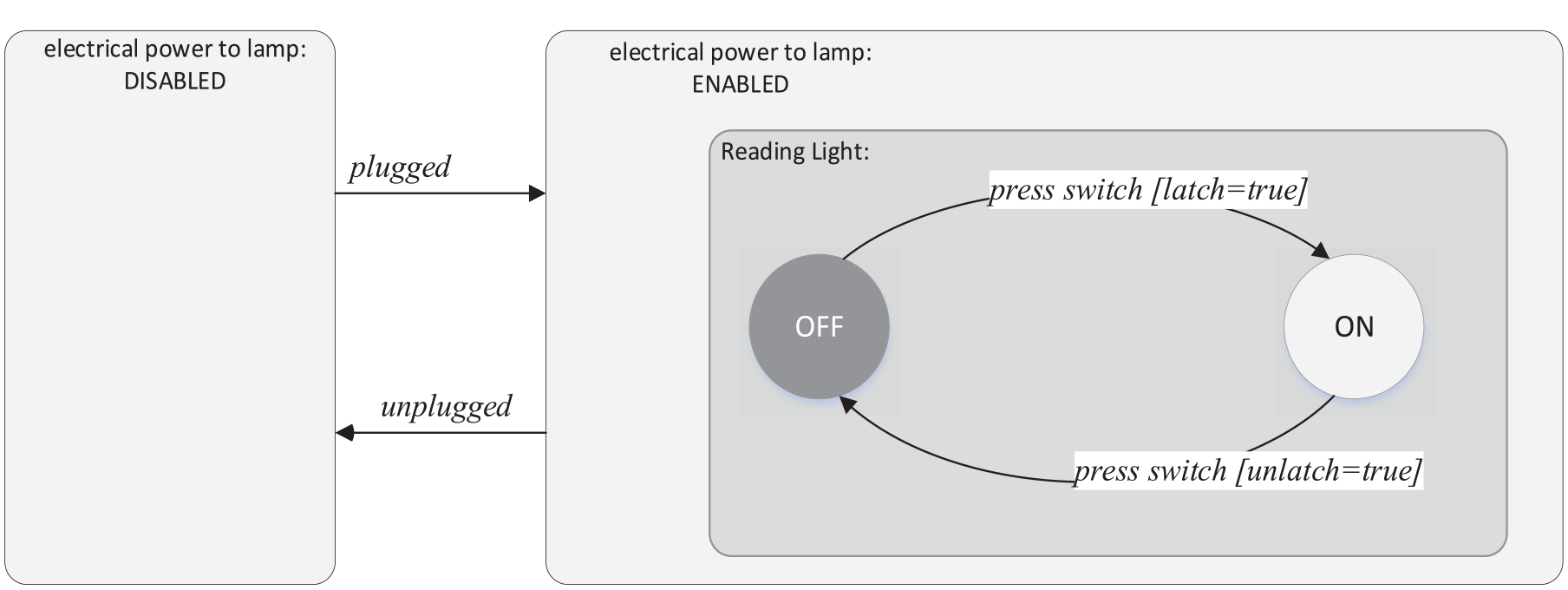
Machine model of a reading lamp.
However, if the switch does not latch, the current will not flow, and the light will not go on. The model indicates this condition by qualifying a conditional [latch=true] for the switch press event. A user, however, is not privy to whether the latch is true or false and cannot reliably determine if the transition to
These behavioral features of the reading lamp system can be depicted in the machine model. Note, however, that the formal model says nothing about the size of the lamp, the materials it is made of, its color, or the luminosity of its bulb—or anything about the switch’s shape and ergonomics.
This type of model nevertheless enables a designer to identify those features of a design that could lead to operator confusion (see, e.g., Degani et al., 2022). For example, if the switch is pressed and the light fails to go on, the user does not know whether the latch did not occur, the electrical power was not enabled, or the lightbulb had burned out. Formal methods of this kind can be used to identify potential design vulnerabilities and usability concerns in far more complex systems, such as the one described next.
Boeing 737NG and 737MAX
The Boeing 737 is the most widely used airliner model in the history of aviation. At any given time, there are more B737s in the air than any other transport aircraft. The two fatal B737MAX-8 accidents—one in Indonesia in October 2018 (National Transportation Safety Committee [NTSC], 2019) and one in Ethiopia in March 2019 (EAAIB, 2022)—shook the aviation industry and led to the unprecedented global grounding of the MAX fleet.
Pitch/Trim System
In both accidents, the pilots failed to overcome the inputs of the Maneuvering Characteristics Augmentation System (MCAS) to the horizontal stabilizer (see Barshi et al., 2023). The stabilizer is a large surface on the airplane’s tail that can be moved up or down. The airplane’s pitch trim system utilizes the aerodynamic impact of these movements to relieve the amount of pressure that needs to be applied from the flight controls when the aircraft is maneuvered along its pitch axis (nose up or nose down) as well as to maximize aerodynamic efficiency. The act of moving the stabilizer to relieve control pressure is called “trimming.” For instance, when pilots want to decrease airspeed while maintaining their altitude, they reduce power and gradually increase the airplane’s pitch attitude to produce the lift needed to hold altitude. Instead of continuously pulling back on the control column, the pilot can trim the horizontal stabilizer to a position that will maintain the desired pitch attitude, removing the need for continual manual force on the control column.
In the B737, the pilots can directly trim the stabilizer in two ways: either by manually rotating the large trim wheels located on the center pedestal between the pilots, or by pressing a pair of two thumb switches located on the control yoke that activate an electric motor that moves the trim wheels and the stabilizer itself. The autopilot of the B737 also uses an electric trim when it controls the aircraft, as well as the speed trim system that is standard in all B737 models, and MCAS, which is a subcomponent of the speed trim system that is only found on the B737MAX. The B737MAX is a derivative of the B737NG (Next Generation); that is, the design and the regulatory certification of the MAX were based on the certified and widely used B737NG model. The MAX was designed to be minimally different from the NG to reduce certification changes and training requirements. The most important difference between the NG and the MAX was new engines that are more efficient, quieter, and less polluting. Although the pitch trim systems on the two aircraft models only varies slightly, this difference was influential in these accidents.
Pitch Trim System of the B737NG
The design of the pitch trim system involves several subsystems and multiple components. Here we focus on the transition of the electric trim motor from the engaged state to the disengaged state, which is related to the introduction of MCAS. There are two cardinal states:
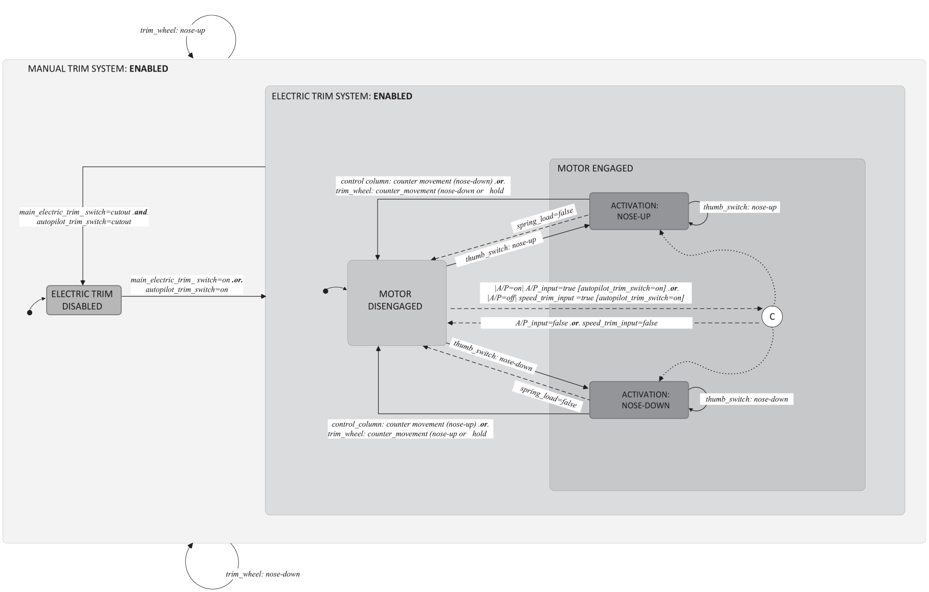
Machine model of the B737NG trim system.
If erroneous input is transmitted to the electric trim motor, the aircraft can transgress into a potentially dangerous pitch attitude that can either be too high, potentially leading to an aerodynamic stall, or too low, leading to a dive. The pilot may be able to momentarily hold the controls to prevent the aircraft from reaching an undesirable pitch attitude. However, the stabilizer aerodynamic forces at an extreme deflection are very powerful and difficult to overcome and may exceed the pilot’s physical ability to manually counter the pitch movement generated by the stabilizer.
This extreme deflection, when it occurs automatically as a result of erroneous inputs, is referred to as a “runaway trim” in aviation lingo. To limit the extent of possible pitch mis-trim, pilots can use a mechanism installed under the cockpit floor (referred to as the “floor switch”) that automatically disengages the electric trim motor when the pilot moves the control column substantially in a direction opposite to the trim input. For instance, if the speed trim system erroneously commands continuous nose-up trim, the pilot, to maintain the desired flight path, can respond by pushing the control column forward. When the floor switch threshold is attained, the trim motor is stopped. This stops the trim motor from moving the stabilizer any further. The control column countermovement is represented in the model as one of the two events that can trigger the trim motor to transition from the ENGAGED to the DISENGAGED state.
On the B737NG, moving the control column in the opposite direction to the movement of the stabilizer stops the movement regardless of whether the electric trim motion is commanded by the pilot’s electric thumb switch or by the automation (autopilot and speed trim system). The same logic applies for aircraft nose down and aircraft nose up movements.
Pitch Trim System of the B737MAX
(Note that the discussion below is focused on the original design of the pitch trim system on the B737MAX. Significant changes to that design were made following the accidents and the grounding of the MAX fleet).
The introduction of new engines on the B737MAX led to major changes in the aircraft’s aerodynamics. To counter the aircraft’s tendency toward nose up, the MCAS was designed to create forward pressure on the control column during manual flight (i.e., when the autopilot is not engaged), flaps retracted, and at a high angle of attack approaching a stall condition (NTSB, 2019). This forward pressure was induced by commanding the horizontal stabilizer on the aircraft’s tail to be trimmed nose down. Because the MCAS was designed to produce forward pressure on the control column when the pilot is pulling the control column back, this counter action could not be allowed because it would cause a trim motor disengagement. The MAX’s floor switch was therefore disabled when the MCAS was moving the horizontal stabilizer in the nose down direction (NTSB, 2019). Note that this modification of the floor switch only applied to the MCAS nose down activation but not to the MCAS nose up activation.
Analysis of the Trim/Pitch System
Figure 3 is a model of the pitch trim system of the B737MAX. It depicts this specific disablement modification as well as all the other differences from the B737NG model. The control column counter-movement is depicted as an event triggering the transition from the
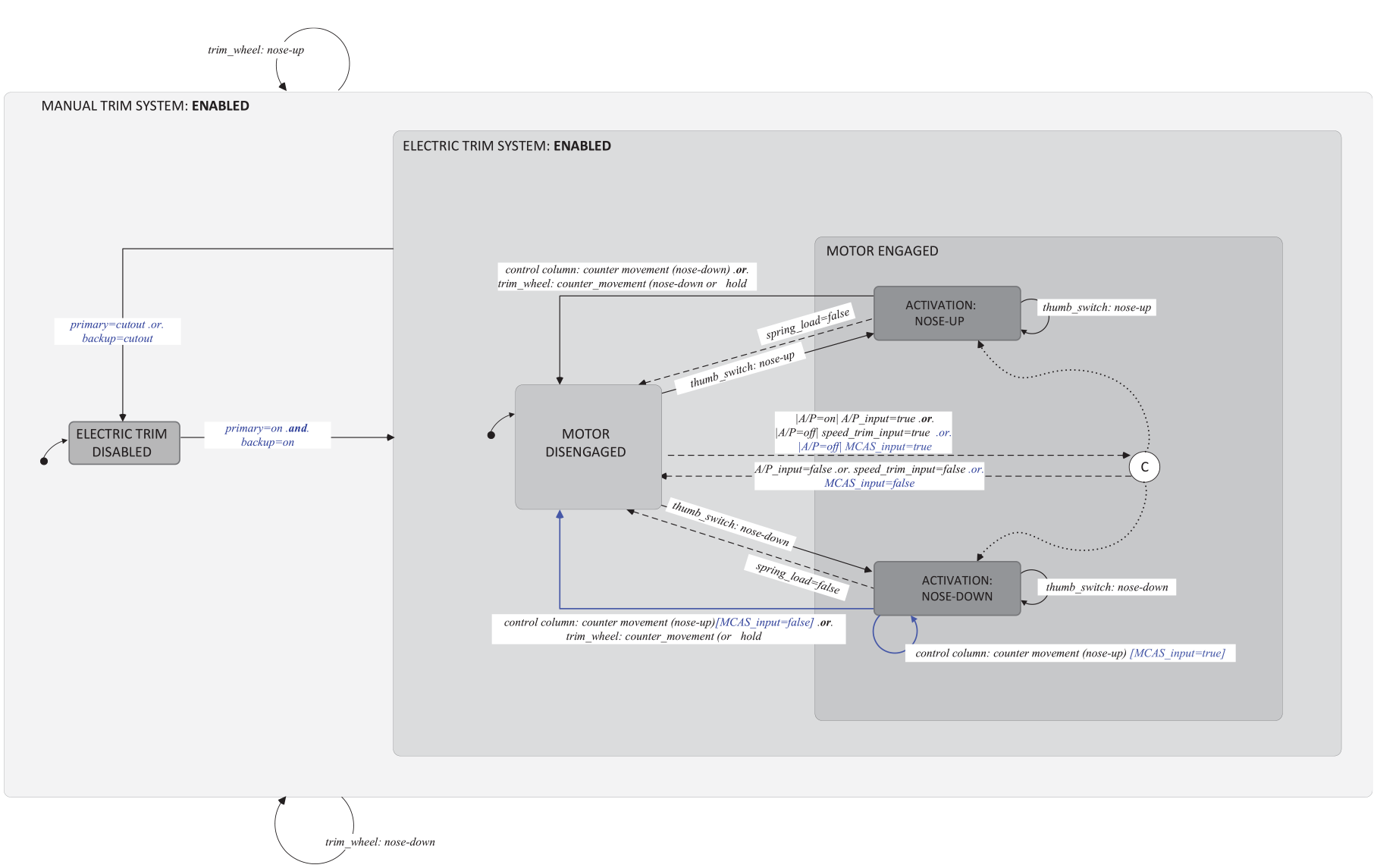
Machine model of the B737MAX trim system superimposed on the same system of the B737NG (changes from the NG are marked in blue).
Our analysis revealed that this modification produces a design vulnerability and usability concern that can lead to operator confusion. This design vulnerability was thus related to the pilots’ inability to reliably predict the result of counter-movement actions of the control column. Pulling back on the control column when the electric trim motor was moving the stabilizer nose down was expected to disengage the motor when the movement was commanded by thumb switches, the autopilot, or the speed trim.
However, when the nose down movement was commanded by MCAS, pulling back on the control column did NOT disengage the motor, and nose down activation continued. Since the flight deck interfaces do not indicate which system is providing trim input, it is impossible for the pilot to predict the outcome of his or her counter-movement. From the pilot’s perspective, the system is unpredictable in the sense that it behaves non-deterministically.
The usability concern results from the lack of symmetry between the motion of the electric trim motor in nose down versus nose up inputs. In the B737MAX, when the electric trim moved the stabilizer nose up, the control column movements in a direction opposite to the stab movement would always disengage the motor regardless of which automated system (autopilot, speed trim, MCAS) was commanding the trim motor. However, when the motor was moving the stabilizer nose down, control column movements in the opposite direction to the stabilizer movement would disengage the electric motor in some cases (when the autopilot or speed trim provide input), but not in others (when the MCAS provides input).
This lack of symmetry between the nose up and nose down movement of the stabilizer engenders confusion because it violated the internal coherency of the design (Brunswik, 1943). Note that this specific usability concern (“lack of symmetry between motions in response to user actions”) could not be resolved even if the MCAS inputs were made visible on the interface and would always lead to potential confusion (See Nielsen, 1994, on “consistency;” Norman & Draper, 1986 and Norman, 1990, on “symmetry” and “mapping”).
Hence a pilot transitioning from flying the B737NG to flying the B737MAX would expect that control column movements in either direction would stop the stabilizer trim motion (whether commanded by the yoke-mounted electric switch or by any automated system). By comparing the machine model to the user model (or in this specific case, by comparing the machine model of the B737NG and the machine model of the B737MAX), the discrepancy between the models makes the source of the expectation confusion quite clear.
MCAS Control
MCAS, when enabled, monitors several aircraft parameters, including speed and angle of attack. The MCAS compares these parameters to respective threshold values. If the current aircraft parameters were within the normal range (i.e., below threshold), the MCAS stayed disengaged. However, when the parameters were above threshold, the MCAS engaged and sends inputs to activate nose down stabilizer trim motions. These trim movement commands produced nose down inputs at a fixed rate of 0.27 degrees per second. After the target value was met, the MCAS stopped the activation of the electric trim motor. The MCAS function would reset, allowing a potential reactivation, if a pilot made a trim input. In the accident flights, each time one of the pilots activated their electric trim thumb switches, MCAS was reset after a delay of 5 seconds (NTSB, 2019).
After the 5 second reset, if the parameters were still above threshold, another activation took place. The original design of the MCAS control logic had no limits with respect to the number of activations. These activations, if not fully countered by the pilot with adequate opposite trim could exceed the pilot’s ability to manually counter the pitch movement generated by the stabilizer (see Degani, 2004, Chapter 15 on transgressions between safe and unsafe regions of operations).
The possibility and the unannounced nature of the transition between a “safe” control region (where the pilot could recover from MCAS accumulation using manual force) to an “unsafe” one (where it exceeded the pilot’s manual force) thus constituted another vulnerability of the original MCAS design. Following the two accidents and the grounding of the MAX fleet, the control logic of the has been changed such that only a single MCAS activation is allowed. Accumulations, either within the pilot manual control region or beyond it, are prevented from occurring.
Discussion
The analysis described here identified one design vulnerability and one usability concern related to the control column modification: non-deterministic behavior of the control column countermovement when the MCAS is active, and the lack of symmetry of control column responses between nose up and nose down while the MCAS is active.
A second design vulnerability concerns the control logic of the MCAS. Because the original MCAS control logic allowed for unlimited nose down activation, the lack of pilot correction in the form of nose up trim inputs led to an accumulation of stabilizer deflection. This accumulation evolved to a point where aircraft pitch control entered an unsafe region of operation, from which the pilots could no longer arrest the aircraft dive using the manual trim wheels or manual control column movement (ECAA, 2019).
Footnotes
Declaration of Conflicting Interests
The author(s) declared no potential conflicts of interest with respect to the research, authorship, and/or publication of this article.
Funding
The author(s) received no financial support for the research, authorship, and/or publication of this article.