
Abstract
A novel damage evolution model for unidirectional (UD) composites is established in this paper in the context of continuum damage mechanics (CDM). It addresses matrix cracking and it is to be applied along with the damage representation established previously. The concept of damage driving force is employed based on the Helmholtz free energy. It is shown that the damage driving force can be partitioned into three parts, resembling closely three conventional modes of fracture, respectively. A damage evolution law is derived accordingly based on the newly obtained expressions of the damage driving force. The fully rationalised Tsai-Wu criterion is employed in the model for predicting the initiation of matrix cracking damage and fibre failure, assisted with the rationalised maximum stress criterion for identifying the damage modes. A mechanism is introduced to describe the unloading behaviour as a part of the proposed model. The predictions were validated against experimental results, showing good agreement with the experiments and demonstrating the capability and effectiveness of the proposed model.
Keywords
Introduction
The concept of damage in the field of composites has been widely employed to describe the degradation of effective properties based primarily on the fact that failure of composites is often a process instead of an incident, starting from initiation of micro-cracks to the final rupture.
The continuum damage mechanics (CDM) is one of the approaches to defining the constitutive behaviour associated with damage. The damage is expressed in terms of a state variable so that the constitutive relationship involving damage can be formulated to describe the effects of damage, as opposed to studying individual cracks at a micro-scale, which is not always practical.
Unlike macro-cracks in metallic materials, where a single dominant crack often dictates the eventual failure, micro-cracks in composites are often dispersed in the matrix, sometimes distributed nearly uniformly (Talreja and Singh, 2012). Due to such distribution of micro-cracks, damaged composites can therefore be regarded effectively as a continuum the effective properties of which can be characterised using an appropriate representative volume element, as well as the damage variable introduced to describe the problem of damage. This lays the basis for CDM.
Damage representation
In the framework of CDM, damage models for composite materials normally comprise two major parts, namely, the damage representation and the damage evolution.
Damage representation interprets the physical presence of damage into a mathematical description by utilising a concept of damage variable. With an appropriate definition of the damage variable, the constitutive relationship for the damaged material could be expressed in terms of a relationship amongst stresses, strains and the damage variable.
However, there appeared to be no unique form of damage representation and different forms of constitutive relationships have been obtained as a result. In fact, this issue was exposed in (Allix and Hild, 2002) where it was also argued that some of the forms of suggested constitutive relationships involving damage that may not even be considered as physically or mathematically sound. This situation should be reviewed and improved.
One of the major differences between various damage representation formulations is the way of accounting for the relationship between the degradations of transverse Young’s modulus E2 and in-plane shear modulus G12. A simple example of such a damage scenario is matrix cracking parallel to fibre direction. This should result in degradations in both transverse modulus E2 (in tension) and the longitudinal shear modulus (G12). The experimental evidence for such damage coupling effect was obtained by Knops and Bögle (Knops and Bögle, 2006), who conducted tests on tubular glass fibre laminate specimens. It was shown that the transverse tensile modulus suffered higher extent of degradation than the in-plane shear modulus.
However, some of the well-known CDM-based damage models for UD lamina employed unrealistic restrictions to interpret this coupled damage effect. In some cases, complete independence between the degradation of E2 and G12 was assumed (Daghia and Ladeveze, 2013; Matzenmiller et al., 1995; Sapozhnikov and Cheremnykh, 2013; Zinoviev et al., 1998), while in others, identical degradations of E2 and G12 was imposed (Edge, 1998; Puck and Schürmann, 2002). None of them can be justified physically or mathematically. This issue was also identified during the third World-Wide Failure Exercises (WWFE-III) activities (Kaddour et al., 2013). Moreover, for general 3D stress problems, in presence of matrix cracks parallel to fibres, there will also be coupling between degradations of G23 in addition to that between E2 and G12, whilst the effective Poisson’s ratios in different directions will be subjected to changes accordingly due to damage.
To address the above problem, some other damage representation models were proposed based on the CDM theory in which the degradation of G12 are determined by the those of E1 and E2 (Gupta et al., 2012; Jain and Ghosh, 2009; Mohammadi et al., 2015; Onodera and Okabe, 2020; Salavatian and Smith, 2015; Thollon and Hochard, 2009; Wang et al., 2015; Zhong et al., 2015). Zhong et al (Zhong et al., 2015) proposed a damage representation model for 3D woven composites including fibre yarns and matrix. In their model, the damage variables representing the damage effects on the shear stiffness of fibre yarns were calculated by the values of the ones characterizing the degradation of longitudinal and transverse modulus. They also considered that the degradation of out-of-plane shear stiffness G23 is determined by the degradation of E2 and E3. Williams et al (Williams et al., 2003) introduced a scalar-valued history parameter to calculate the damage variable and then the residual stiffness functions defined by the damage variables were derived for damage representation.
On the other hand, Li et al. (Li et al., 2019) proposed a damage representation in which the interaction between degradations of E2 and G12 was accounted for without imposing any artificial restriction, leading to a rational model of damage. It was based on the damage formulation proposed by (Talreja, 1985), who employed a vectorial damage variable. This was a relatively simple damage representation, but it had been proven in (Talreja, 1987) that a more sophisticated tensorial damage variable tended to lead to exactly the same constitutive relationship for matrix cracking damage. By means of virtual experiments and associated mathematical derivations, seven out of eight of these damage-related constants were determined analytically. For the determination of the remaining one, a computational procedure has been developed. As a result, the proposed damage representation (Li et al., 2019) minimised the efforts required for determining damage-related material constants. This damage representation has been adopted in the present paper.
Damage initiation criterion and damage evolution law
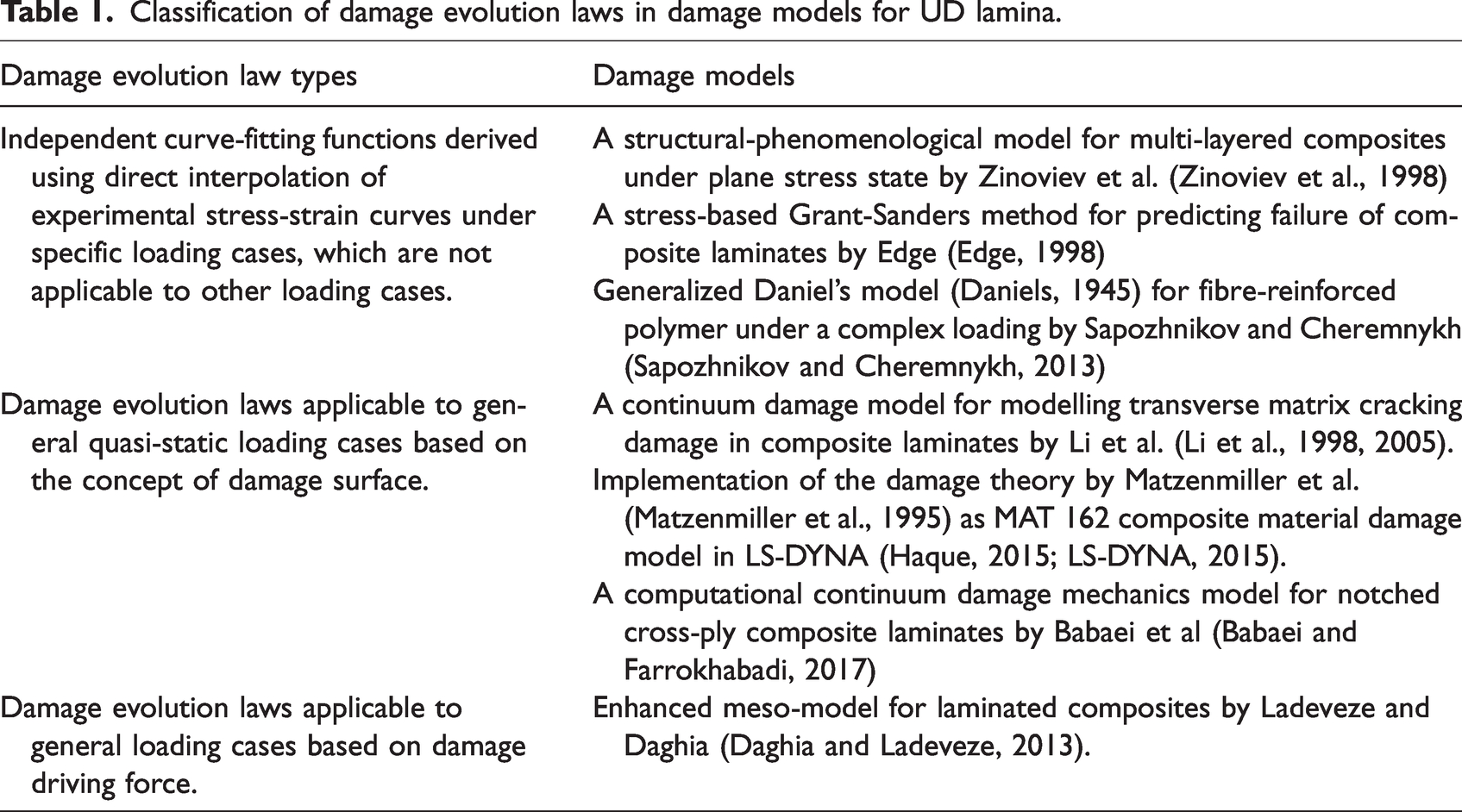
Another integral part of the damage model is a damage evolution that describes the growth of damage. Same as for damage representation, different types of damage evolution laws were also proposed by various researchers. These models can be classified into three categories in general, as shown in Table 1.
Classification of damage evolution laws in damage models for UD lamina.
Apart from the aforementioned models, other researchers proposed numerical methods to address the mechanical properties and cracking problems in UD composites (Galadima et al., 2023), including the extended finite element method (XFEM) (Abdullah et al., 2017; Dimitri et al., 2017; Swati et al., 2019), peridynamics (PD) model (Li et al., 2023; Ni et al., 2023; Sun et al., 2023), lattice model (Braun and Ariza, 2020; Braun et al., 2021, 2024) and so on. Li et al (Li et al., 2023) proposed a highly efficient bond-based PD model to simulate the progressive damage behaviour of laminated composites. In their model, critical values and damage characteristics for different damage modes at material points were defined to predict the evolution of damage in composite structures. Braun et al. (Braun and Ariza, 2020) presented an extended linear elastic lattice model for anisotropic materials. A softening constitutive law in terms of an equivalent displacement was introduced in the model to predict the progressive damage evolution in composite materials. Mukhopadhyay et al (Mukhopadhyay and Hallett, 2019) presented a new direct CDM model for matrix cracking in composites and it is implemented using Abaqus. A damage variable was introduced in the bilinear damage evolution law based on the calculated mixed-mode critical energy release rate. In their model, the fibre orientation at ply level was also used as an input so that individual matrix cracks in cracked plies could be represented and their evolution could be tracked, making their model independent of mesh pattern.
The objective of this paper is to supplement the damage representation formulated in (Li et al., 2019) for matrix cracking damage in UD composites with a novel damage evolution law based on the concept of damage driving force. Whilst retaining the necessary consistency in its formulation, a great simplification will be brought forward by some rigorous mathematical transformation in the presentation of the damage driving force, resulting in three naturally partitioned components directly associated with the corresponding stress components, resembling the conventional fracture modes.
In absence of pre-existing defects or damage, a damage initiation criterion is usually required to trigger the onset of damage process, therefore a complete formulation of the damage model should be supplemented by a damage initiation condition. Failure criteria for UD composites are often employed as the damage initiation criteria, and their comprehensive reviews can be found from the outcomes of WWFEs (Hinton et al., 2002, 2004; Kaddour and Hinton, 2013; Kaddour et al., 2004, 2013; Soden et al., 1998, 2004) and (Echaabi et al., 1996). The recently fully rationalised Tsai-Wu criterion (Li et al., 2022a, 2022b) will be employed for damage onset, assisted with the rationalised maximum stress criterion (Li, 2020) for the identification of the damage mode. The predicted damage initiation has also been compared with that obtained using the Puck criterion (Knops, 2008) in terms of damage initiation and its knock-on effects on the subsequent damage process.
In addition to predicting the onset of the transverse matrix cracking damage in laminated composites under quasi-static loading, the failure criterion employed can also help with the prediction of catastrophic failure modes like fibre failures. The model has been formulated in such a way that it is applicable to general loading conditions including unloading and reloading scenarios, a mechanism not present in many existing damage models, yet crucial in representing the effective of irreversible nature of a damage process. Finally, the predicted results will be compared to experimental data from quasi-static tests on composite laminates to validate the model developed.
Damage representation for matrix cracking in UD composites
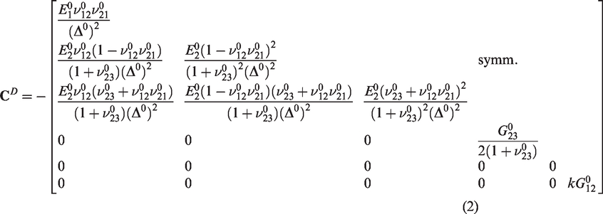
The damage representation established by Li et al. (Li et al., 2019) is adopted in this paper to incorporate the effects of damage in the form of matrix cracks on the elastic behaviour of UD composites. According to it, the effective stiffness matrix of transversely isotropic UD composites in presence of a single array of aligned matrix cracks can be given as


A novel damage evolution model for UD composites subject to matrix cracking
In order to establish a complete damage model, the damage representation should be supplemented by appropriate damage onset conditions and damage evolution law. This is pursued in the following subsections.
Damage initiation criterion
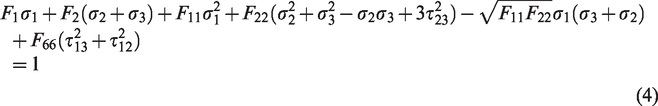
Built on top of the knowledge acquired through the World-Wide Failure Exercises (WWFEs) (Hinton et al., 2002; Kaddour and Hinton, 2012; Kaddour et al., 2013a, 2013b), two most popular criteria, viz. the maximum stress criterion and the Tsai-Wu criterion have been fully rationalised recently (Li, 2020; Li et al., 2022a, 2022b). Together, they can offer a complete damage initiation criterion, with the rationalised Tsai-Wu criterion for the damage onset and the rationalised maximum stress criterion for the crack orientation as the damage mode.
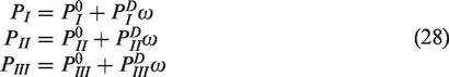
The rationalised Tsai-Wu criterion for UD composites under a general 3D stress state can be given as follows (Li et al., 2022a, 2022b)


The maximum stress criterion was rationalised primarily in the plane transverse to fibres (Li, 2020), in the sense that failure transverse to fibres should be determined by
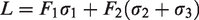
As illustrated in Figure 1(a), the transverse failure plane in UD composites is always parallel to the fibre direction. Under transverse loading, from the equilibrium conditions for the free body diagram as illustrated in Figure 1(b), the following two equations can be obtained

Illustration of transverse failure plane in UD composites.
By combining the above two equations and eliminating σM, the angle between the maximum direct stress and the coordinate axis 2 is given as

Under uniaxial transverse tension, the normal to the failure plane is identical to the direction of the applied tensile stress σM according to the rationalised maximum stress criterion (Li, 2020), on which the shear stress is equal to zero. One has θt = θ = 0.
Under a uniaxial transverse compression stress condition (when τ23 = 0), the failure is primarily due to the transverse shear stress on the fracture plane. According to the Mohr’s circle, the maximum shear stress is found on a plane ±π/4 from the direction of applied compressive stress (also ±π/4 from the direction of σM which is 0 in magnitude in this case). As θ is equal to 0, the angle between the failure plane and axis 2 can be obtained as

The experimental result is obtained as 56.5°, and a commonly-used test value is 53° (Tao et al., 2017). Besides, the Puck criterion (Knops, 2008) also predicted an angle slightly different from ±π/4.
The longitudinal shear failure is determined by the maximum longitudinal shear stress


Once damage onset is predicted by the rationalised Tsai-Wu criterion, the following ratios will be examined


UD composite matrix cracking damage orientation definition.
The damage evolution model
Having introduced the damage initiation criterion, a novel damage evolution law is proposed below to describe the evolution of matrix cracking under general quasi-static loading.
Derivation of damage driving force
To be consistent with the damage representation derived from the Helmholtz free energy density, it is natural to derive the corresponding damage evolution law based on the concept of damage driving force from the same energy as well, offering a natural connection in the theoretical framework between damage representation and damage evolution.
For vector field characterization of damage in composites, a damage vector V = [v1 v2 v3]
T
defined in (Li et al., 2019; Talreja, 1985) was introduced, which is shown as follow,

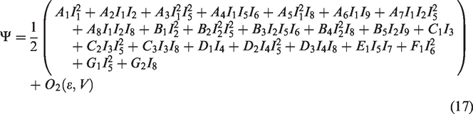
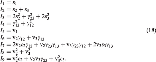
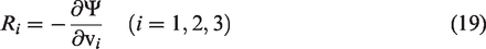
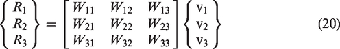
It should be noted that since energy is being released from the material during a cracking process, negative sign is introduced here to reflect this negative gain. The damage driving force can be expressed in general as follows
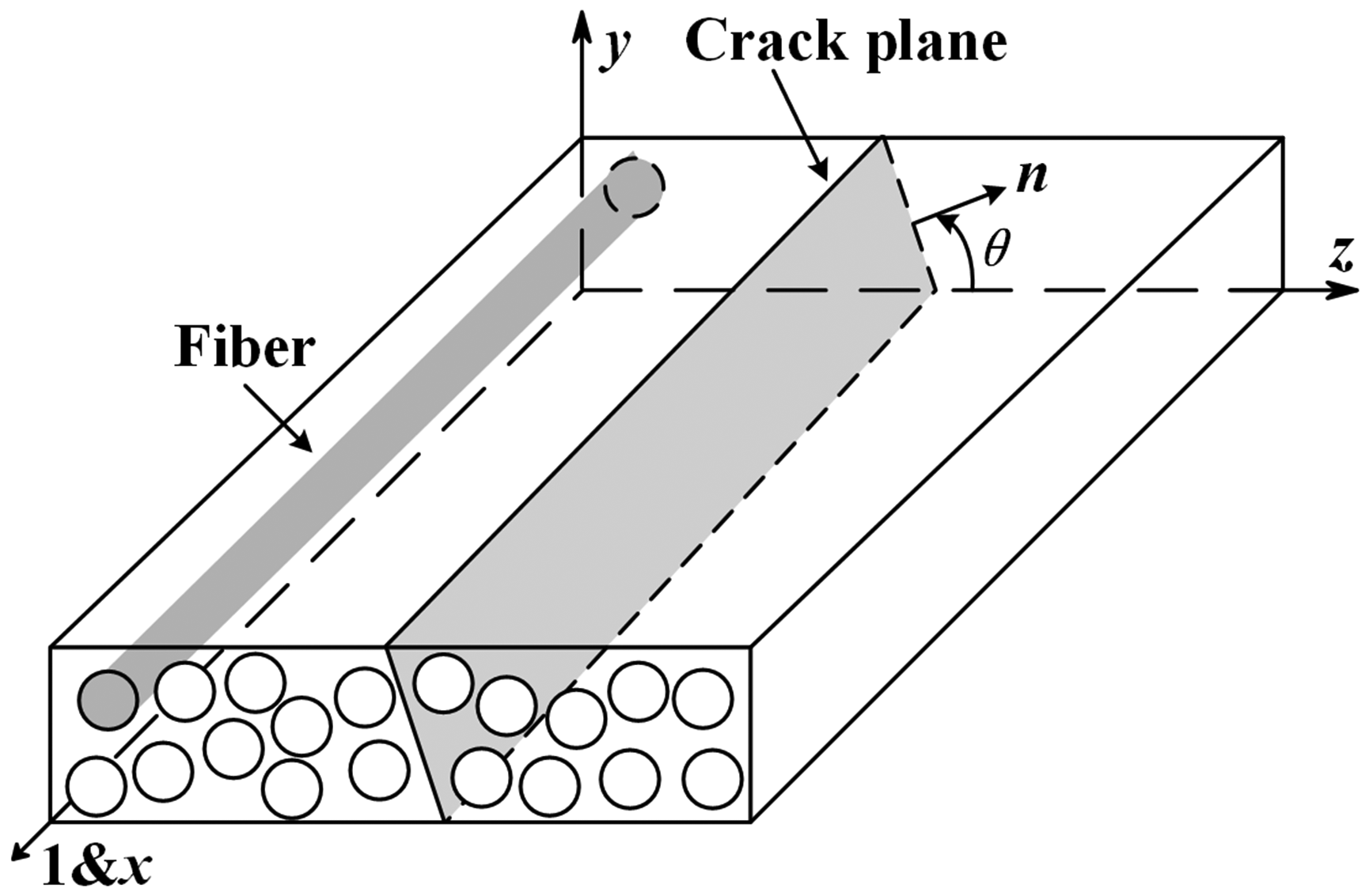
Referring to Figure 2, the local coordinate system can be so chosen that the damage vector
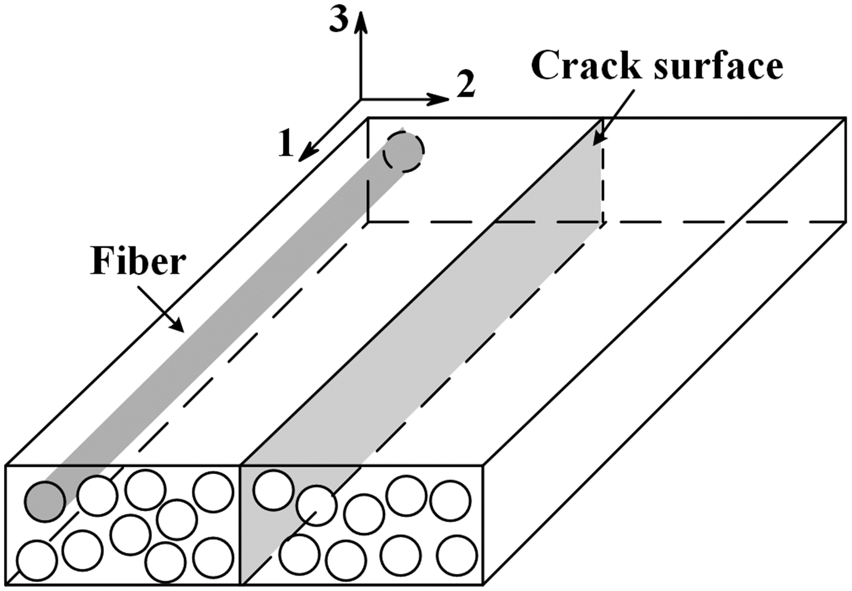
Rectangular material coordinate system assigned to UD composites.
Assume that as the damage evolves, microcracks keep their orientation, as is usually the case in the most popular scenarios of transverse matrix cracking in laminated composites. In other words, R1 and R3 would not make any difference as there is no relevant damage components for them to drive, no matter how significant their values become. Component R2 will be the only one having effects on the damage evolution. Given v1 = v3 = 0, one has


Before the material undergoes any deformation, G2 would be the only non-vanishing term in W22, implying the presence of damage driving force Ri even then, provided that damage v i is not zero. The same argument also applies to the constant term of G1 in W11. Obviously, such a scenario corresponds to a case in presence of initial damage in the material. For simplicity, G1 and G2 are set to zero, implying the absence of initial damage for the subsequent development in this paper.
Recall the relationship between damage vector component v2 and damage parameter ω in (Li et al., 2019),


After linearization with respect to ω under the assumption of small damage, i.e., ω≪1, one obtains
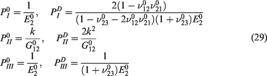
As a result, the damage driving force ρ in (25) for the specific form of damage, i.e., matrix cracking, can be expressed as
As shown in equation (27), there are only three non-zero elements in matrix [P], and they dictate the damage driving force ρ. Expressions (27) to (29) were rigorously derived analytically, although use was made of mathematical software Maple (Maplesoft, 2014) to ease the mathematical manipulations. The sparce appearance of [
The expression of the damage driving force derived above and the damage representation previously established in (Li et al., 2019) are fully consistent. Assisted with the damage initiation criterion and the identification of the damage mode as proposed in Section ‘Damage initiation criterion’, a novel and complete matrix cracking damage model has been formulated.
From (28), (29) and (30), it can be seen that the newly derived damage driving force ρ can be expressed explicitly in terms of the effective elastic constants of the undamaged UD composites, the damage parameter and stresses, without introducing any new constants as fudge factors, and its physical dimension is the same as stresses. In this case, under a loading condition in which stresses increase monotonically, damage driving force ρ would increase accordingly according to (30). In such a loading process from a stress-free initial state, the damage evolution process is triggered when the damage initiation criterion is satisfied.
If ρ is regarded as the total damage driving force, it consists of three parts as naturally partitioned in (30). Similar to the concept of mixed mode fracture, the three parts of the damage driving force should be counted independently in order to form a damage growth law in a mixed mode sense as is the subject of the next subsection.
Critical damage driving forces and a mixed mode damage growth law
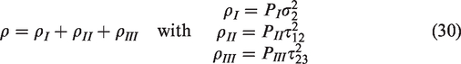
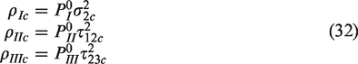
The total damage driving force ρ as obtained above is apparently not completely determined by the material properties. It is also affected by the loading conditions, i.e., different stress ratios. This is similar to the observation in fracture mechanics where critical total energy release rate is not a material property but varies with the mode ratio. It has to be partitioned into individual modes and compared with their respective critical values, GIc, GIIc and GIIIc, before the mixed mode problem can be meaningfully addressed (Anderson, 2017). The same argument applies to the total damage driving force. Critical values as material properties will have to be associated with individual modes, i.e., ρIc, ρIIc and ρIIIc. Each of these critical damage driving forces has to be obtained under a single mode of loading right up to the point of damage growth as follows:
Based on above discussion, the total damage driving force ρ is divided into three parts, which represent corresponding individual modes respectively for mixed-mode loading cases. Some kind of mixed mode damage evolution law will have to be resorted to as in the case of mixed mode fracture. Let
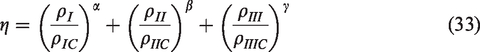

Although constants α, β and γ could each take different values and should be determined by fitting available experimental data to achieve a best fit, the lack of sufficient experimental data renders a fairly arbitrarily selected value of α = β = γ = 1 or 2 as a practical approximation as is also case in the practices of mixed mode fracture mechanics (Anderson, 2017).
Damage evolution law and incremental material constitutive relationship
From the derivation of damage driving force, the quantities driving the evolution of damage have been clearly identified, and they determine whether the damage will grow. However, an additional relationship is required between the damage driving force and the amount of damage growth.
For this, an incremental relationship is presented as follows. Since damage growth is driven by damage driving force, it is then conceivable that the magnitude of damage should be a function of the three independent components of the damage driving force, i.e.

Imagine the critical state for damage initiation is met once the values of the damage driving force components reach ρI0, ρII0 and ρIII0 at a given damage level ω0. One can expand the function in (35) into a Taylor’s series in the neighbourhood of the state. Neglecting terms of orders higher than the first, the following equation is obtained,


This is the incremental relationship between the damage and the components of the damage driving force. In general, damage-evolution-related constants for a given material system, μI, μII and μIII in (37), correspond to each of the three different modes and therefore take different values, implying that loads in different modes make different contributions to damage growth.
It also can be seen from (37) that the damage evolves only when the components of the damage driving force produce a positive value for Δω. Otherwise, unloading takes place, as will be addressed in the next subsection.
According to the continuum damage mechanics, the second law of continuum thermodynamics leads to the following Clausius-Duhem inequality (Murakami, 2012),

In our model, the inelastic strain is not considered, and a uniform temperature field is assumed. So, the above inequality leads to the following condition,

Hence, satisfying the above inequality will ensure our proposed damage evolution law thermodynamically admissible. This inequality imposes restrictions on the values of damage-evolution-related constants μI, μII and μIII such that the incremental damage value Δω predicted by (37) should always satisfy (39) after (39) is approximated by its incremental form instead of rate form.
The incremental form of ρI, ρII and ρIII can be given as
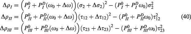
Substituting them into (37) yields
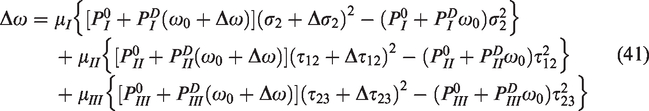
It should be noted that the incremental stress terms Δσ2, Δτ12 and Δτ23 in (40) are also dependent on incremental damage Δω. Based on the constitutive relationship (3), one has
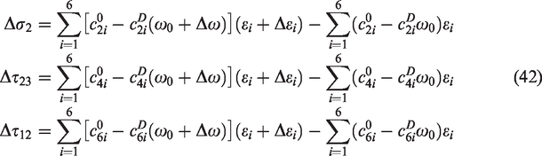
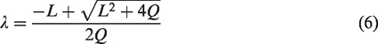
It is obvious that (41) is a nonlinear and implicit algebraic equation of the damage increment Δω. To solve for Δω from (41), Newton’s iterative method is employed with (42) incorporated in the algorithm as presented in Appendix 1.
The tangential stiffness matrix could also be obtained as given in (52) in Appendix 1 as a part of the Newton’s iteration mentioned above. It is required in an implicit finite element analysis (FEA) solver, such as ABAQUS™/Standard when a user defined material subroutine is resorted to for the implementation of the above damage model in a structural finite element analysis. It should also be pointed out that there are many damage evolution laws in commercial software based on energy or displacement. The present model is a material model. It defines the state of damage and the evolution of the damage at a material point. In practice, the model will be applied to each integration point. Existing damage models in commercial software are different. For instance, the continuum damage model in Abaqus is defined on a plane or surface, through which decohesion is simulated, as conventionally described as cohesive zone model. Such planes or surfaces, have to be predetermined so that cohesive elements can be pre-planted
Unloading and reloading scenarios
It should be noted that when the material is unloaded after loading, the value of Δω becomes negative according to (37). However, damage evolution is an irreversible process, unless the material possesses self-healing function which is not available for conventional composites. Therefore, once negative value for Δω is predicted, it signifies the start of unloading process. The damage evolution should pause and the current level of damage should remain unchanged during the unloading process. An appropriate unloading criterion can be given as

With the unloading process introduced, there is also the issue of reloading when the previously unloaded material is loaded up again. For such a scenario, since damage evolution process has been suspended during previous unloading process, a reloading criterion is needed to indicate that the damage evolution process is expected to resume during reloading stage. It should be the logical opposite of the unloading criterion, .i.e.

Unless it is satisfied, the damage state will still remain unchanged.
Incorporation of instant failure criteria
Apart from capturing the effects of damage growth associated with matrix cracking, the possibility of fibre failure should also be monitored. If a fibre failure mode is identified from (14), i.e., either of the ratios exceeds 1, a fibre failure is predicted. It should be noted that the fibre failure predicted here is a local failure mode. The ultimate failure of the structure like a composite laminate is characterised by the loss of load carrying capability of the structure concerned. However, any local fibre failure often appears as a close precursor to the ultimate failure in a composite structure.
Implementation of proposed damage evolution law and its verification and validation
The damage model has been formulated under a general 3D stress condition. It is therefore applicable to problems of such nature. However, due to the availability of experimental data that can be employed as validation cases, the subsequent discussion will be specialised to a plane stress state for its applications to structures of laminated composites that can be analysed based on the classic laminate theory (CLT). As a result, the orientation of the microcracks become predetermined so that they fall into the category of so-called transverse matrix cracks. It should be also pointed out that in this paper the proposed damage model was implemented in the software MATLAB (Mathworks, 2017) as the experimental cases adopted for model validation and verification were of macroscopically uniform stress field in each ply.
However, the proposed model could also be implemented easily in the finite element (FE) software to analyse the damage evolution in composite structures under quasi-static loading. To implement the model in this paper, the tangential stiffness matrix has been derived as presented in equation (52) in Appendix 1, which is a matrix variable required to be updated in the subroutine. To calculate the change of damage variable in a loading increment, the Newton’s iterative method is employed in our model, as presented in Appendix 1, and the obtained values are also updated in the subroutine as required. With the use of subroutine, the proposed damage model will become applicable to the analysis of problems involving macroscopically non-uniform stress.
Several experimental results of glass fibre laminates were adopted for model verification and validation. Due to the limitation of test equipment, only the strain-stress curves of composite laminates were recorded in the tests, and the longitudinal stiffness degradation was derived from it for comparison with the predicted results of longitudinal stiffness properties of these composite laminates.
Among the adopted experimental results, two laminate test cases are employed to determine damage-related material property μI as a first attempt. The corresponding experiments are as follows:
Uniaxial tensile tests on UD laminates in their transverse direction to determine the transverse tensile strength Yt which is associated with the initiation of matrix cracking in mode I. Uniaxial tensile test on cross-ply laminates of UD laminae to determine the damage-related constant μI for mode I type matrix cracking damage.
Verification with E-glass/MY750 composite laminates
Determination of material parameters
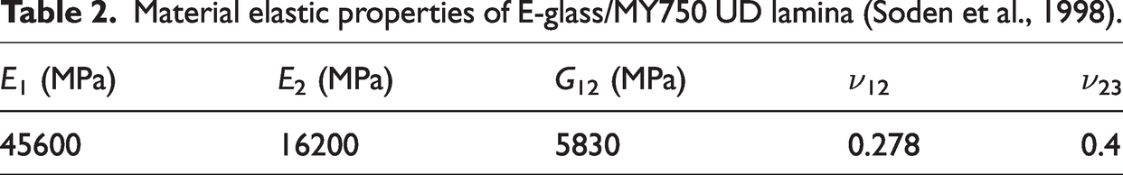
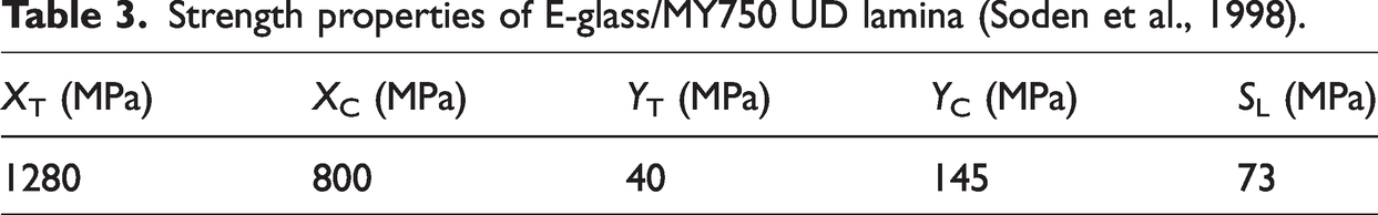
Experimental data obtained for the E-glass fibre [0/90]s laminate in WWFE-I (Soden et al., 1998, 2002) were adopted to validate the proposed damage model. The particular laminate of interest consists of UD laminae, which was made of Silenka 1200tex E-glass fibre and MY750 epoxy. The corresponding UD lamina material elastic properties and strength properties as provided in (Soden et al., 1998) are summarised in Table 2 and Table 3, respectively.
Material elastic properties of E-glass/MY750 UD lamina (Soden et al., 1998).
Strength properties of E-glass/MY750 UD lamina (Soden et al., 1998).
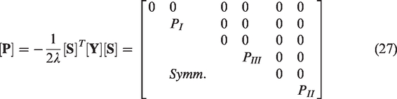
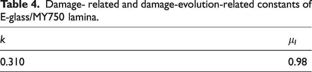
In the model, the value of factor k for the coupling effects of damage between the transverse tension and in-plane shear was determined in the same manner as in (Li et al., 2019) and the obtained value is given in Table 4. In order to determine the damage-evolution-related constants μI in the damage evolution law, use has been made of the experimental data obtained under uniaxial tension. In general, the stiffness reduction of the cracked lamina, i.e., the damage parameter ω, can be extracted from the laminate stiffness reduction based on CLT, provided that the specimens for the test are so designed that under the loading condition, there is only one lamina that is subjected to cracking damage. Similarly, the effective stress transverse to fibres in the cracked lamina could be extracted from the average stress in the laminate, given the uniaxial loading condition to the laminate, also based on CLT. The damage driving force ρI in the cracked laminae can be obtained from (30). Only the non-zero element PI in [P] in (27) can be evaluate, given (28) and (29), and the value of ω. The relationship between ω and ρI directly obtained from experimental results were plotted in Figure 4 as discrete data points. Damage-evolution-related constant μI was obtained as the gradient of the straight line fitted to the experimental data, as shown in Figure 4, and the obtained value is given in Table 4.
Damage- related and damage-evolution-related constants of E-glass/MY750 lamina.
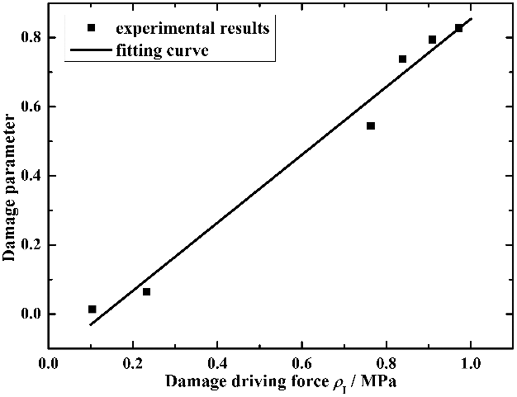
Determination of damage-evolution-related constant μI based on experimental results.
Results and discussion
To assess the accuracy of predictions, stress-strain curve for E-glass/MY750UD fibre cross-ply laminate under tensile loading was calculated and compared with experimental results from (Soden et al., 1998, 2002) in Figure 5. Close agreement between the predicted and the experimental stress-strain curves is apparent. Given that some of the input data were derived from the experimental results, the agreement can only serve as a necessary ‘sanity check’, an important verification.
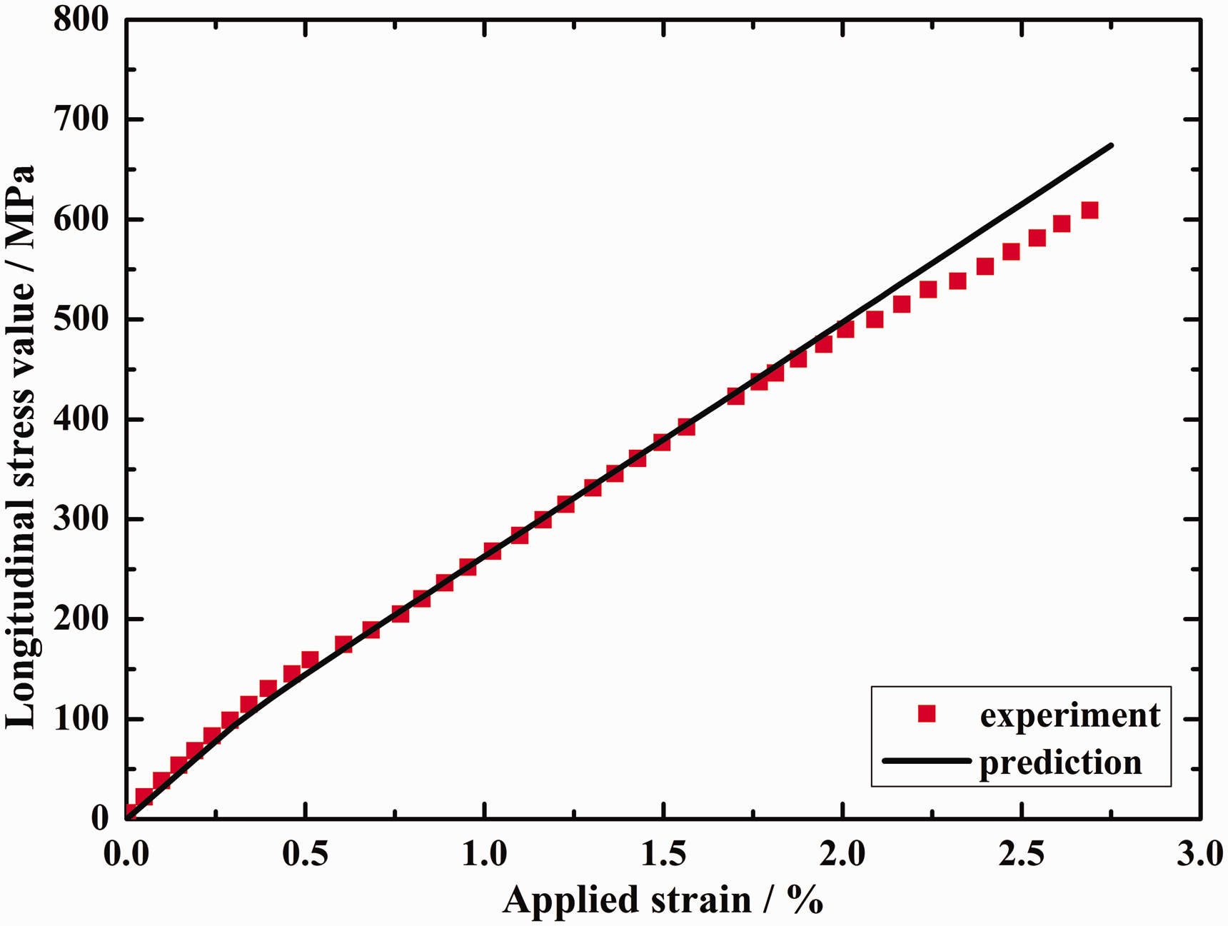
Comparison of the stress-strain curve with the experimental results for E-glass/MY750 [0°/90°]s laminate.
The variation of the predicted damage variables in the 90° and the 0° plies with the applied strain has been plotted in Figure 6. As can be seen, in addition to cracking damage in the 90° plies, damage was also predicted in the 0° plies at later stage, once the transverse stress in the 0° plies reached transverse tensile strength and thus triggered transverse matrix cracking in the 0° plies. The Poisson’s effect and the constraint provided by the fibres in the 90° plies to the 0° plies were responsible for this. Specifically, as the laminate was gradually loaded, the 0° plies tended to shrink in the transverse direction due to Poisson’s effect. However, stiff fibres in the adjacent 90° plies tended to impede this tendency, resulting in the transverse tensile stress build up in the 0° plies, which eventually resulted in transverse cracking in 0° plies, which was sometimes described as longitudinal splitting damage in the 0° as reported in the cross-ply laminate specimen in (Daniels, 1945), when tensile strain exceeded 1.25%.
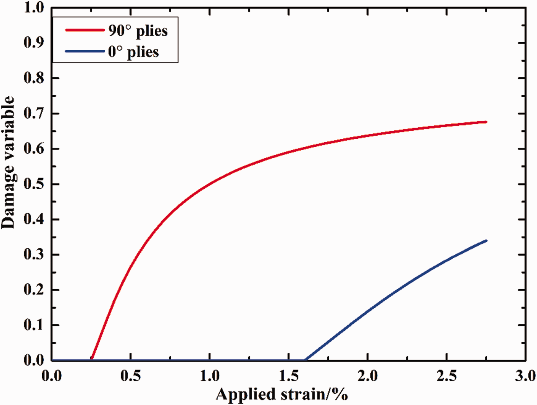
Damage parameter as function of strain in E-glass/MY750 [0/90]s.
Verification and validation against E-glass/YPX3300 laminates
In order to validate the proposed model in predicting the degradation of stiffness properties of composite laminates, experimental results of E-glass/YPX3300 cross-ply laminates as reported in (Shen et al., 2017) were employed, involving two different lay-up configurations, [0°/90°4]s and [0°2/90°4]s. The experimental results from the former had been employed to extract the required material properties as the input to the model. Independent predictions were made to both laminates. Whilst the prediction made to the [0°/90°4]s laminate served as a necessary verification, the agreement between the prediction and the experimental data for the [0°2/90°4]s laminate offered a meaningful case of validation. Key experimental data employed either for material property extraction or for comparisons with the predicted results were the average stress-strain curves, from which longitudinal moduli of the laminates at different states of damage could be obtained. The obtained tangential moduli were presented graphically after being normalized with respect to the longitudinal moduli of the laminates at their undamaged states.
Determination of material parameters
The elastic and strength properties of E-glass/YPX3300 UD lamina are shown in Table 5 and Table 6, respectively.
Material elastic properties of E-glass/YPX3300 UD lamina (Shen et al., 2017).
Strength properties of E-glass/YPX3300 UD lamina (Shen, 2016).
The damage-related constant for E-glass/YPX3300 was determined following exactly the same procedure as described previously, utilising the experimental stress-strain curve for [0°/90°4]s laminate from (Shen, 2016). The obtained value is given in Table 7.
Damage- related and damage-evolution-related constants for E-glass/YPX3300 lamina.
Results and discussion
Employing the obtained damage-evolution-related constants and applying the damage model to both laminates, i.e. [0°/90°4]s and [0°2/90°4]s, the deformation and damage process in both laminates can be predicted. The results in terms of normalized longitudinal modulus are compared with the experiment data in Figure 7. The first case is in fact not truly predictive as the experimental results had been employed to extract the damage-evolution-related constant. The degree of agreement as shown in Figure 7(a) serves at least as a promising verification. The discrepancy indicates the level of error in the damage model, given various simplifications and approximations introduced in the model. In the model, both the damage representative and damage evolution model deals with transverse matrix cracking damage in composite materials, which dominates the early stage of damage evolution process. Experimental results show that the typical damage evolution process in composite materials could be divided into three main parts (Talreja and Singh, 2012). At early stage, the main damage mode is transverse matrix cracks. As the increase of loading, the matrix cracks tend to saturate and local delamination starts to emerge at the tips of matrix cracks, leading to a further degradation of stiffness properties of materials. At the later period, fibre breakage and some other diffuse damages would exist, and these damages could cause the final failure of composite structures. Since the present model only addresses the transverse matrix cracks, the influence of other damage modes is not considered, leading to the differences between prediction and experimental results, especially when the applied stress load is large. Moreover, The proposed model also ignored the nonlinear elastic behaviour of composite materials under quasi-static loadings. Experimental results show that the longitudinal modulus of composite laminates start to decrease due to the tensile nonlinearity before the initiation of matrix cracks (Shen et al., 2017), but this effect is not included in our present model, leading to the differences between the prediction results and experimental results. Given the complex nature of the damage problem, the error should fall in an acceptable range for engineering applications.
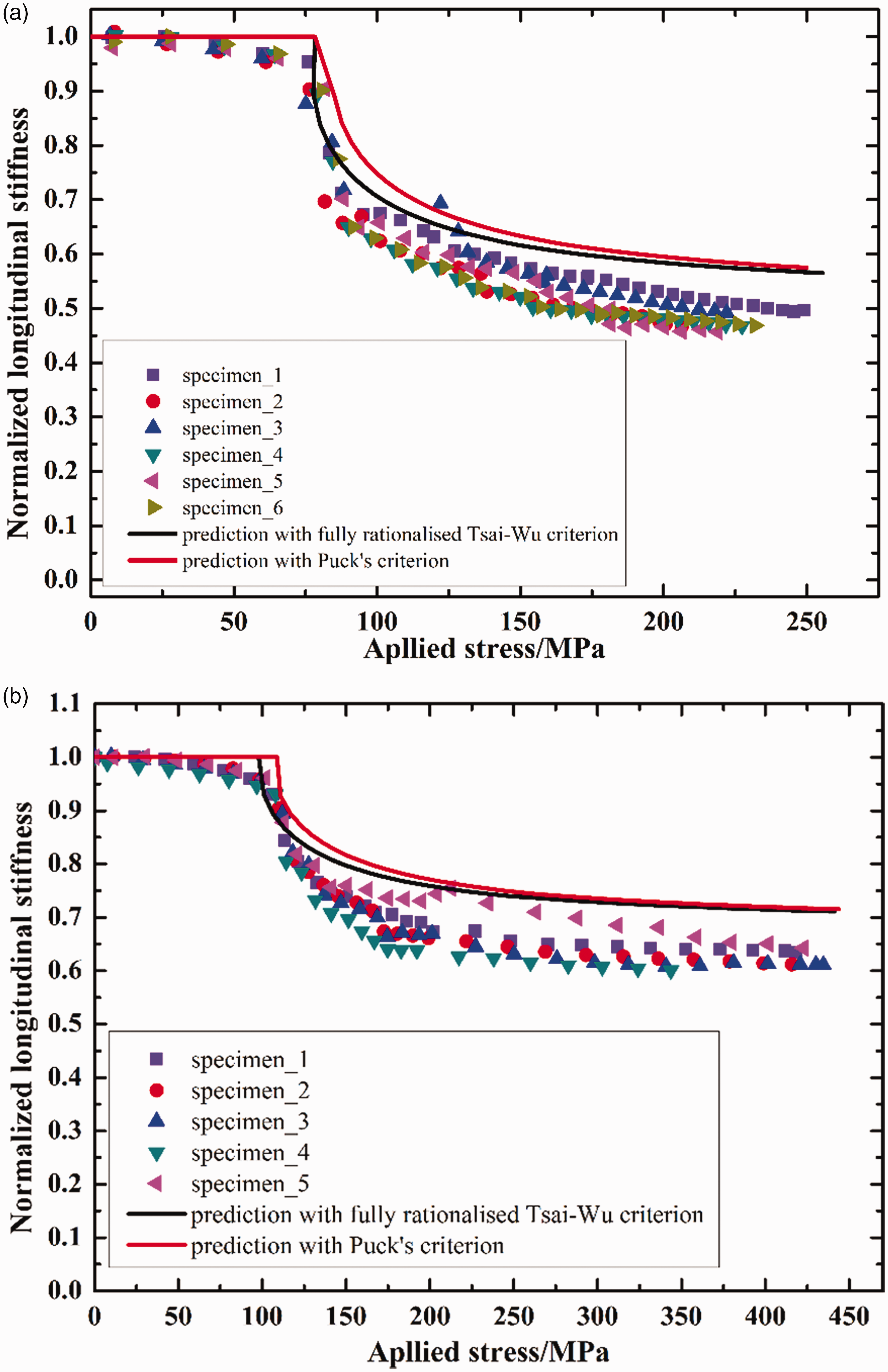
Comparison of normalized longitudinal modulus between prediction results and experimental results of E-glass/YPX3300 laminates. (a) [0°/90°4]s, (b) [0°2/90°4]s.
The results as presented in Figure 7(b) should be considered true predictions in a sense that the experimental results for this case had not been employed directly or indirectly. The agreement with experimental data is certainly satisfactory, at least no worse than that in Figure 7(a).
Note that there are two curves shown in Figure 7(a) and (b). One in black corresponds to the damage model where damage onset is predicted with the rationalised Tsai-Wu criterion, while for red curve, damage initiation was predicted based on the Puck criterion, as was originally used in (Yu, 2016). No significant differences have been observed. However, recent efforts on the full rationalisation of the Tsai-Wu criterion (Li et al., 2022a, 2022b) rendered the formulation free from any fudge factors and it is also much simpler to implement than the Puck criterion. The identification of failure modes can be satisfactorily accommodated by adopting the mode identification scheme based on the rationalised maximum stress criterion (Li, 2020) as described in subsection ‘Damage initiation criterion’ previously.
Model verification with fiberite/HyE 9082Af composite laminates
Apart from the verification in predicting the stiffness degradation of cross-ply laminates, experimental results in (Joffe and Varna, 1999) were also adopted to validate the proposed model in predicting the stiffness degradation of composite laminates with off-axis plies. In their experiments, the specimen was made from Fiberite/HyE 9082Af, and the configuration of laminates was [±θ/90°4]s with θ = 0°, 15°, 30° and 40°.
Determination of material parameters
The basic elastic properties and strength properties of Fiberite/HyE 9082Af UD lamina are shown in Table 8 and Table 9, respectively (Joffe and Varna, 1999; Moure et al., 2014). Out of the four laminates, the experimental results from the [30°2/90°4]s laminate were employed to extract the damage-evolution-related constant of this type of composite and the obtained value are listed in Table 10. The comparison with the experimental results obtained from the remaining three laminates would serve as validation cases.
Material elastic properties of Fiberite/HyE 9082Af UD lamina (Joffe and Varna, 1999).
Strength properties of Fiberite/HyE 9082Af UD lamina (Moure et al., 2014).
Damage-related and damage-evolution-related constants of Fiberite/HyE 9082Af lamina.
Results and discussion
The comparisons between the predictions and experimental results are shown in Figure 8 in terms of the degradation of the normalized longitudinal modulus. Out of the four laminates corresponding to Figure 8(a) and (d), the case for Figure 8(c) should be considered as a verification, as it is meant to reproduce the test case from which the input data were extracted. It is a laminate with off-axis plies. Under uniaxial tension, an in-plane along-fibre shear stress is generated. Any discrepancy between the prediction and the experimental data gives a good indication of possible errors in the model due to the assumptions and approximations employed. The agreements as shown in the remaining three cases in Figure 8(a), (b) and (d), respectively, for laminates of different layups are valid cases of validation of the model.
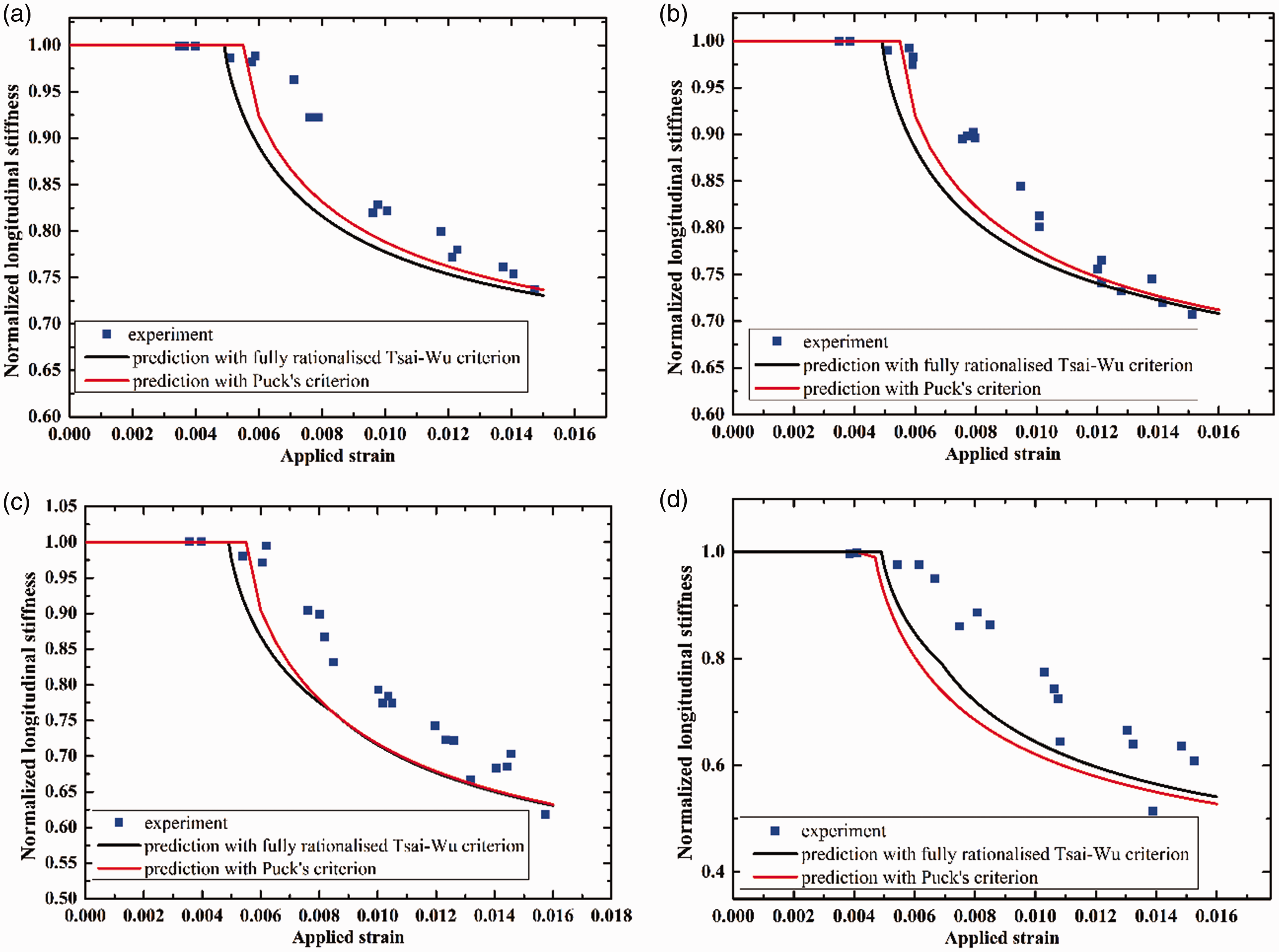
Comparison of normalized longitudinal modulus between prediction results and experimental results of Fiberite/HyE 9082Af laminates. (a) [0°2/90°4]S, (b) [15°2/90°4]S, (c) [30°2/90°4]S, and (d) [40°2/90°4]S.
The predicted results of stiffness degradation of composite laminates with off-axis plies as shown in Figure 8 are generally in good agreement with experimental results, indicating the capability of proposed model in predicting stiffness degradation of both cross-ply laminates and laminates with off-axis plies due to transverse matrix cracking damage under quasi-static loading.
It should be noted that the in-plane shear nonlinearity in presence of off-axis plies in the laminate makes the problem significantly more complicated if the interactions between this nonlinearity and that caused by damage are considered (Li et al., 2005). A consistent approach of incorporating along-fibre shear nonlinearity under a general 3D stress state has been formulated in (Li et al., 2021). Whilst it is of interest to incorporate such interactions in the new damage model, it is beyond the scope of this paper and will be pursued as a future development. A significant part of the disparity between the predicted results and the experimental data can be attributed to this consideration. In addition, the neglect of other damage modes, e.g., local delamination at crack tips at increasing loading would lead to the further errors between the prediction results and experimental results, as discussed in part of subsection ‘Verification and validation against E-glass/YPX3300 laminates’.
Again, predictions using the Puck criterion for damage initiation have also been included in Figure 8. They remain comparable with the present results.
Conclusion
In this paper, a new damage evolution model is formulated based on the concept of damage driving force to predict the initiation and evolution of transverse matrix cracks in composite materials under quasi-static loading. The expression of the damage driving force can be presented in a decoupled form with each component corresponding to a mode resembling one of the three well-known modes of fracture. At the implementation level, the Newton’s iterative method has been derived to deal with the nonlinearity involved in the problem. This damage evolution law is formulated at macro scale, although it is to model the effects of micro cracks in the composite. First attempt has been made to incorporate the fully rationalised Tsai-Wu failure criterion (Li et al., 2022) to predict the damage initiation and the fully rationalised maximum stress criterion (Li, 2020) to predict the damage modes in the composite. The newly formulated damage evolution model takes account of unloading and reloading based on appropriately proposed criteria for these processes respectively to duly reflect the irreversible nature of damage. Hence the model could be used to predict the deformation of composite structures involving damage initiation and evolution when the structure is under complex loading conditions. With the help of classical laminate theory, it can also be applied to laminates of arbitrary layups although for the examples in the present paper only one of them has been used. The application of the new model requires only three newly defined damage-evolution-related material properties that can be extracted from a set of appropriate tests on a simple laminate layup before the model can be applied to laminates of arbitrary layups under arbitrarily loading cases.
Several sets of the experimental results for glass fibre reinforced composite laminates were adopted for the verification and validation of new model, including the stress-strain curves and stiffness reduction as a function of the applied load. Good agreements have been observed in general.
It should be pointed out that due to the neglect of nonlinear elastic behaviour of composite materials, the proposed model cannot deal with damage behaviour of composite materials involving significant nonlinearity, and this would be addressed in the further work. Besides, both the damage representative model and damage evolution model in the present model deal with transverse cracking damage only in uniaxially fibre reinforced composites, which dominates the early stage of damage evolution process. The evolution of some other damage modes, for instance, local delamination and fibre breakage, are not considered. These damages often initiate and develop after the saturation of transverse matrix cracks and would lead to the final failure of composite structures. Hence, the present model is only limited to transverse cracking damages and cannot analyse further damage and failure behaviour of composite materials after the saturation of transverse cracking damage. Considering the difference between fatigue loading and quasi-static loading, the proposed damage evolution model is only valid for predicting the evolution of transverse matrix cracks in composite materials under quasi-static loadings, and it cannot predict the matrix cracks initiation and evolution in composite materials under fatigue loading.
Footnotes
Declaration of conflicting interests
The author(s) declared no potential conflicts of interest with respect to the research, authorship, and/or publication of this article.
Funding
The author(s) disclosed receipt of the following financial support for the research, authorship, and/or publication of this article: The financial support from AECC Commercial Aircraft Engine, Co. Ltd., China, through Grant No. RGS 106619 (from July 2012 to July 2015), is gratefully acknowledged.
Appendix 1
To calculate the increment of damage parameter Δω from (41) with relevant stress increments as given in (42), Newton’s iterative method can be employed as shown below. To facilitate this, rearrange (41) to introduce a new function as follows.
Solving (38) is equivalent to finding an appropriate value for Δω which makes f(Δω) = 0. Newton’s iteration scheme can be employed to find the root for such a homogeneous equation through the following formula:
When the above defined iterations converge, Δωk converges to Δω. It should be used to update the damage state. As a result, the stress state and the tangential stiffness matrix of damaged material incorporating evolving damage variable can be determined at a given deformation state (ε + Δε). According to stress-strain relationship as given in (3), its incremental form can be obtained in a straightforward manner, from which the current stress state can be obtained as follows, where boldface letters are employed to stand for tensor for the neatness of the expressions involved.
Differentiate the above with respect to Δ
The tangential stiffness [
Re-arranging (55), one obtains
With this, the evaluation of the tangential stiffness as given in (51) can be fulfilled.