
Abstract
In the excavation of water-related underground projects such as hydropower and energy reserves, the surrounding rock surfers complex stress path and stress state redistribution, resulting in damage and failure under the hydro-mechanical coupling condition. However, the rock hydro-mechanical coupling characteristics under complex stress paths are unclear and corresponding theoretical models are scarce. In this study, a series of tests such as triaxial compression, unloading confining pressure and cyclic loading and unloading were carried out to study the effects of different stress paths, stress levels and seepage pressure on rock deformation, strength, failure and permeability. Based on test results, the damage evolutions under three different testing paths were analyzed, a new seepage-stress coupling statistical damage model which can better simulate the compaction stage is proposed. The prediction results of the proposed model under different stress paths are in good agreement with the experimental results. Under different stress paths, the fitting relationship between parameters R0 and n and σeff is similar and has good correlation.
Keywords
Introduction
Seepage-stress coupling characteristics of rock is a hot issue in the field of rock mechanics and engineering. When rock engineering is carried out under the groundwater level, the external load and internal seepage pressure act on the rock mass with a multi-scale discontinuous structure at the same time. The coupling effect of stress and groundwater significantly affects rock strength and deformation behavior and even leads to a series of serious engineering disasters, such as the collapse of dams and earthquakes caused by injection (Rutqvist and Stephansson, 2003; Ye and Ghassemi, 2018). In addition, during the excavation and operation of rock engineering in the reservoir area, the stress states of the rock are constantly changing, the stress conditions are complex, while there are few studies on the mechanical and permeability characteristics of brittle rock under different stress paths. Therefore, it is of great significance to investigated the hydro-mechanical coupling behaviors and model of brittle rocks under different stress paths for guiding engineering project construction.
Through laboratory experiments on rocks, extensive results have been achieved in the seepage-stress effect (David et al., 2001; Zhang et al., 2016; Zhou et al., 2021). By conducting a series of triaxial compression tests, the researchers found that porosity has a great influence on the permeability of rock, and the shear zone has a great influence on the relationship between the two (David et al., 2001). From the analysis of laboratory test results of high-permeability rocks such as sandstone and shale, it can be seen that effective stress also has an important influence on the permeability and porosity of high-permeability rocks (Xu et al., 2018, 2023; Zhang et al., 2016; Zhao et al., 2017). The stress dependence of rock porosity and permeability attenuation is analyzed by exponential law and power law (Su et al., 2022). Callovo-Oxfordian and Opalinus claystones are good potential host rocks as radioactive waste repositories, and their hydraulic behavior has been extensively studied over the past decade, especially the stress-strain-permeability behavior of clay rock in the pre-failure stage (Amann et al., 2014; Jobmann et al., 2010; Popp and Salzer, 2007), establishing that the change in the permeability of clay rock with damage and remodeling can be done through empirical models (Zhang, 2016). Yang et al. (2023) studied the mechanical properties of rock crack propagation, conducted true triaxial hydraulic fracturing tests on shale, and monitored the internal failure mode of shale by acoustic emission detection system. Wang et al. (2015) analyzed the relationship between rock failure strength, deformation and permeability of sandstone and limestone under triaxial compression, and the evolution characteristics of erosion permeability before and after rock failure. High-permeability soft rock (such as coal rock, sandstone, etc.) has always been a hot topic of research, but the research on low-permeability brittle hard rock (such as granite) is relatively small.
Underground rock engineering undergoes complex stress changes, such as the construction and excavation of underground oil storage caverns and coal mining. From the perspective of mechanics, it is a typical unloading process. In past studies, unloading test research on rock mostly focused on the study of unloading stress paths (Huang and Huang, 2014; Jia et al., 2019; Qiu et al., 2014), unloading rates (Chen et al., 2018; Zhou et al., 2018) or geometric parameters (Zhou et al., 2014). Zhao et al. (2014) studied the relationship between rockburst characteristics and the unloading rate of Beishan granite under unloading conditions through the visualization of acoustic emission changes and rock failure fragments. To study the influence of cyclic loading and unloading on the surrounding rock, cyclic loading and unloading tests were carried out on coal rock, which provided the basis for the design of the support rock column of the mining well (Medhurst and Brown, 1998), and quantitative analysis of the deep landslide was carried out by introducing the loading and unloading response ratio (Zhang et al., 2006). Chen et al. (2018) conducted uniaxial stress perturbation tests on sandstone and found that cyclic stress would temporarily increase the strain rate of the rock; that is, the efficiency of stress corrosion cracking of the rock was greatly improved. Wang et al. (2021) analyzed the fracture evolution and energy characteristics of marble through a series of fatigue cyclic loading and unloading and confining pressure unloading tests. Most of the above studies focus on the mechanical properties of rocks, and there are few studies on the permeability characteristics of rocks under the conditions of unloading confining pressure and cyclic loading and unloading. Oil storage and export is a cyclic loading process on the rock mass in the reservoir area. Changes in the rock stress state will cause changes in its permeability, while groundwater infiltration often leads to engineering accidents such as seepage and water inrush. Therefore, it is necessary to conduct in-depth experimental research on the permeability characteristics of low-permeability rocks under various stress paths and different stress states, and the research results can provide experimental support for the design and operation of underground rock engineering.
To better simulate the rock stress–strain relationship, the researchers established the rock constitutive model on the basis of damage mechanics, combining mathematical statistics and continuous medium mechanics (Bai et al, 2020; Ju, 1989, 1990; Lemaitre, 1984; Zhao et al., 2021), and obtained good simulation results. Bennett and Borja (2018) established a phenomenological model to better describe and calculate the macroscopic damage mechanical behavior of rocks, but there are still some defects in the microstructure evolution of materials. Zhao et al. (2018) and Zhang et al. (2019) complement previous scholars' research by establishing a micromechanical model. Research scholars (Chen, 2020; Shen et al., 2012; Wang and Ma, 2022; Zheng et al., 2023b, 2023c, 2023e) established a model combining the two kinds of mechanics by analyzing the macro mechanics and micro mechanics of materials, and supplemented the limitations of the above two theories. Zhu (2017) established a new damage micromechanical constitutive model of porous rock based on the continuum micromechanics and thermodynamics theory by eliminating the porosity, initial porosity and the generation of new cracks in the rock, that is, the expression of the three-phase system material of rock skeleton, quasi-brittle rock material. In order to solve the problem of many parameters in the model, Sumelka (2014) introduced a new fractional plasticity theory, and researchers (Liang et al., 2019; Sun et al., 2020; Sun and Shen, 2017; Sun and Sumelka, 2019; Zheng et al., 2023a) achieved good simulation results through further development. The above model is mainly based on the characteristics of dry rock, and the damage model under water-rock coupling is less studied. There are large numbers of microcracks and microvoids inside natural rock, and there is a compaction effect, and the above models are not considered. So there is a lack of hydro-mechanical coupling damage model for rock with rich natural micro-fractures.
In order to overcome the limitations of previous studies, triaxial seepage-stress coupling tests were carried out for granite under different stress paths (triaxial compression, triaxial unloading confining pressure, and triaxial cyclic loading and unloading) in this paper. The strength-deformation characteristics and permeability evolution law of granite under seepage-stress coupling were studied. The relationship between effective stress and volume strain and permeability is analyzed, and the cause of permeability hysteresis loop is discussed. Based on the test results, a new seepage-stress coupled statistical damage model considering the intermediate principal stress effect and the initial compaction effect is established. The influence of effective stress on the failure mode of granite, the change rule of permeability under different stress paths, and the change of deformation parameters of granite under cyclic loading and unloading were further discussed.
Testing methodology
Specimen preparation and test facilities
The test rock samples are granite from the Late Proterozoic period, which was sampled by on-site core drilling in an underground cave reservoir area in China. The rock samples are located in a deep stratum, the whole is relatively complete, there is no visible crack, it is light blue–gray, there are white spots inside and the cementation is tight. According to the suggested method of the International Society for Rock Mechanics and Rock Engineering (ISRM) (Fairhurst and Hudson, 1999), the specimens are processed into a standard cylinder with a height of 100 mm and a diameter of 50 mm. A typical specimen is shown in Figure 1.
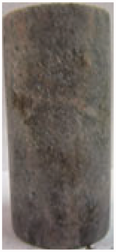
Typical granite specimen.
The test equipment employed is a rock automatic multifield coupling triaxial servo-controlled system, as depicted in Figure 2. This equipment comprises a stress application chamber, a pressure system, a stress stabilization unit, a stress servo system, a seepage pressure control facility, and an automated data storage system. High-precision control during loading can be carried out by means of automatic compensation measures and servo system; the maximum error does not exceed 0.1 MPa, the maximum axial stress is 500 MPa, the maximum confining pressure is 60 MPa, and the maximum seepage pressure is 30 MPa. The strain acquisition system of the test equipment can measure the rock deformation with an accuracy of 0.1 µm and can process and draw the stress–strain curves in real-time through the computer recording system.
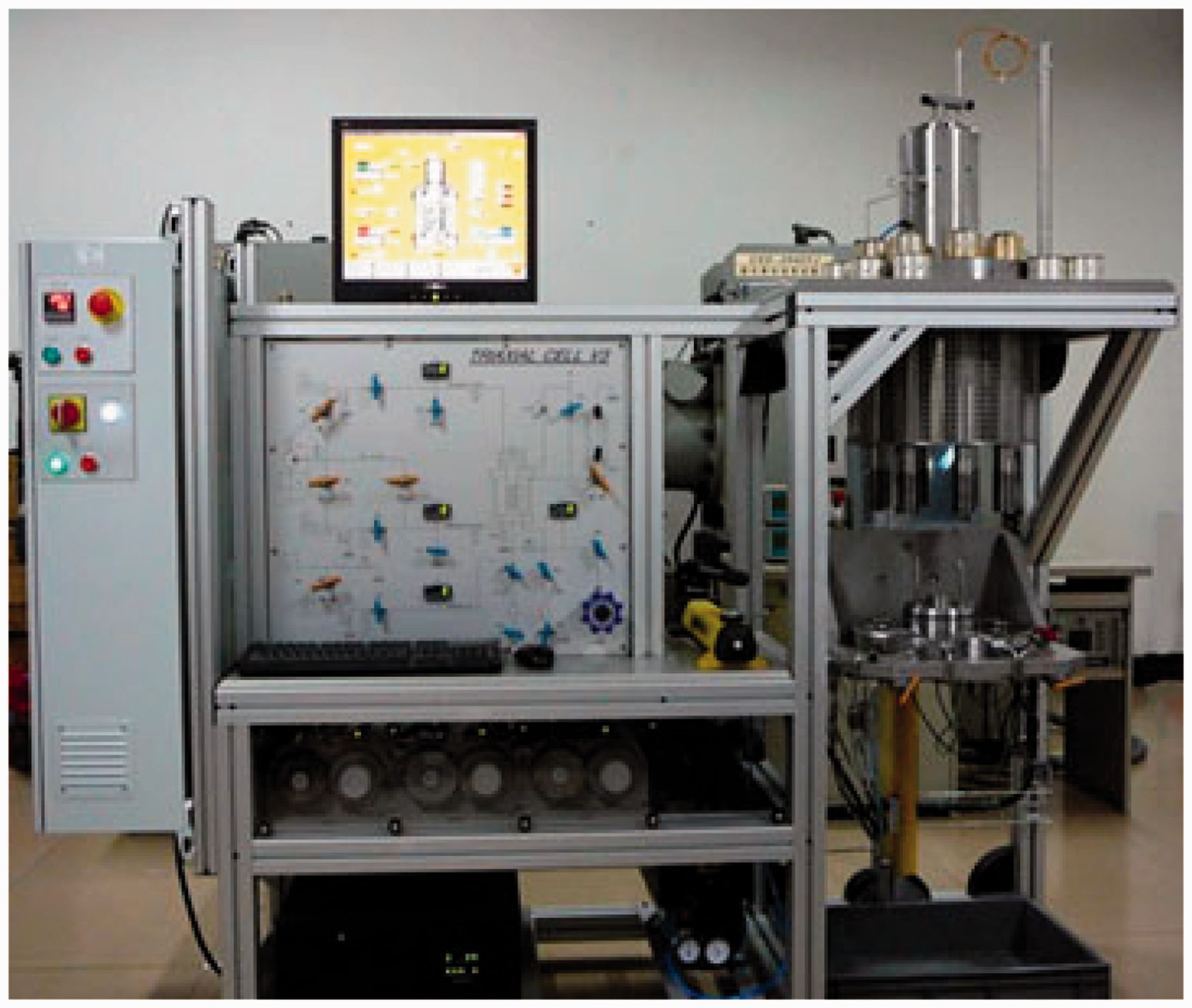
Rock triaxial servo-controlled system.
Test procedures and scheme
Through the geological exploration report of the underground cave reservoir area, considering its in-situ stress environment and hydrogeological conditions, the minimum principal stress range is between 3 and 10 MPa, the maximum principal stress is between 13 and 16 MPa, and the seepage pressure is relatively stable. Considering the diversity of the stress state of the rock environment, three test schemes of triaxial compression, triaxial unloading confining pressure, and triaxial cyclic loading and unloading of axial stress are adopted.
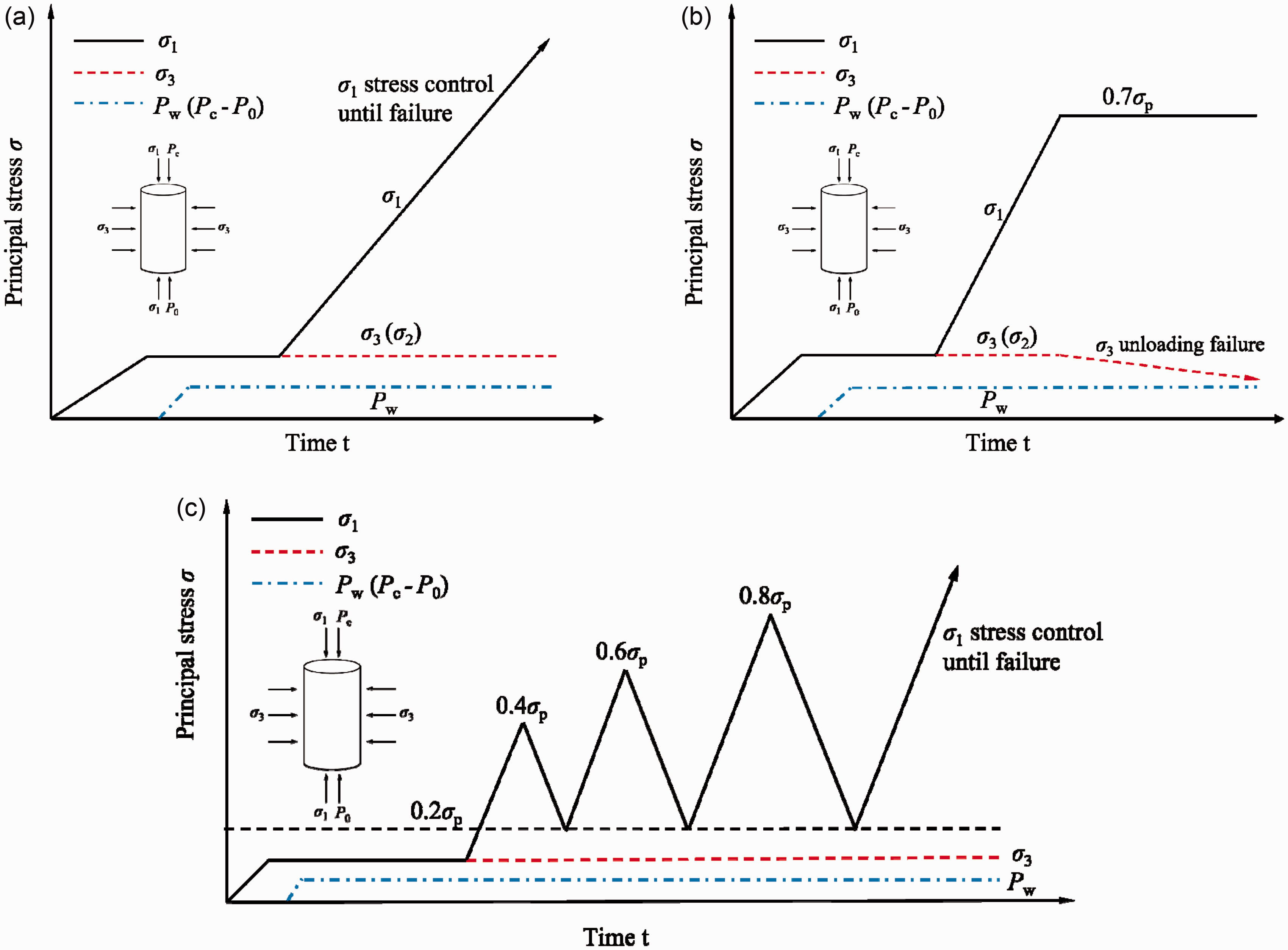
The triaxial compression test is divided into two stress situations of different confining pressures σ3 when the seepage pressure Pw is constant and different seepage pressures when the confining pressure is the same: when the seepage pressure is 1 MPa, the confining pressures are 2, 4 and 6 MPa, respectively; the confining pressure is 4 MPa, and the seepage pressures are 1, 2 and 3 MPa, respectively. The stress path of the specimen is shown in Figure 3(a). First, load the σ3 to the set value at a speed of 0.1MPa/min. Then, loading the seepage pressure Pw (Pc–P0 is the seepage pressure difference) to a predetermined value while keeping the confining pressure stable. The granite is saturated for approximately 4 h, and load the stress at the rate of 0.75 MPa/min until the granite specimen failure.
Test stress path diagram. (a) Triaxial compression test; (b) triaxial unloading confining pressure test and (c) triaxial cyclic loading and unloading test. The Pw is set to 1 MPa and the σ3 to 6 MPa and 10 MPa in the unloading confining pressure test, and the stress path is shown in Figure 3(b). The application of confining pressure and seepage pressure is the same as that of the triaxial compression test. Taking the peak strength σp under different confining pressures in the triaxial compression test, the axial compression loading is stopped when the axial stress is 0.7σp, the bias pressure is kept constant, and the confining pressure is unloaded at 3.5 bar/min until failure. The Pw is set to 1 MPa, and the σ3 is set to 2, 4 and 6 MPa in the triaxial cyclic loading and unloading test. The stress path of the specimen is shown in Figure 3(c), and the loading method of confining pressure and seepage pressure is consistent with the triaxial compression test. Stress loading was used. The cyclic loading and unloading were performed at a loading rate of 2.8 MPa/min. Taking the peak strength σp under different confining pressures in the triaxial compression test as the standard, the stress level of each stage of loading is increased by 0.2σp, and all unloading to 0.2σp.
Test results and analysis under triaxial compression
Stress–strain curve characteristics of granite under triaxial compression
To determine the mechanical properties of granite under the condition of seepage-stress coupling, the triaxial compression test was carried out. Figure 4 shows the stress–strain curves of granite under different triaxial stress conditions. Figure 4 shows that with increasing σ3 or decreasing Pw, the lateral expansion deformation capacity of the granite is limited, the bearing capacity of granite gradually increases, and the peak strength increases significantly. The stress-strain curve of granite has obvious linear correlation before the peak, and shows nonlinear behavior after the peak, which is independent of the initial stress. When the granite enters the crack propagation stage and the post-peak stage, the initiation and expansion of microcracks inside granite lead to the nonlinear stress–strain response and the degradation of elastic properties of the granite. The formation of microcracks releases a large amount of elastic strain energy, resulting in damage and fracture. With the increase of deviator stress σ1–σ3, the granite obviously changes from volume compression to volume expansion. When the confining pressure σ3 is small or the seepage pressure Pw is large, the volume expansion of granite is more obvious. As σ3 increases, the dilatancy effect is insignificant due to the limitation of deformation induced by high σ3.
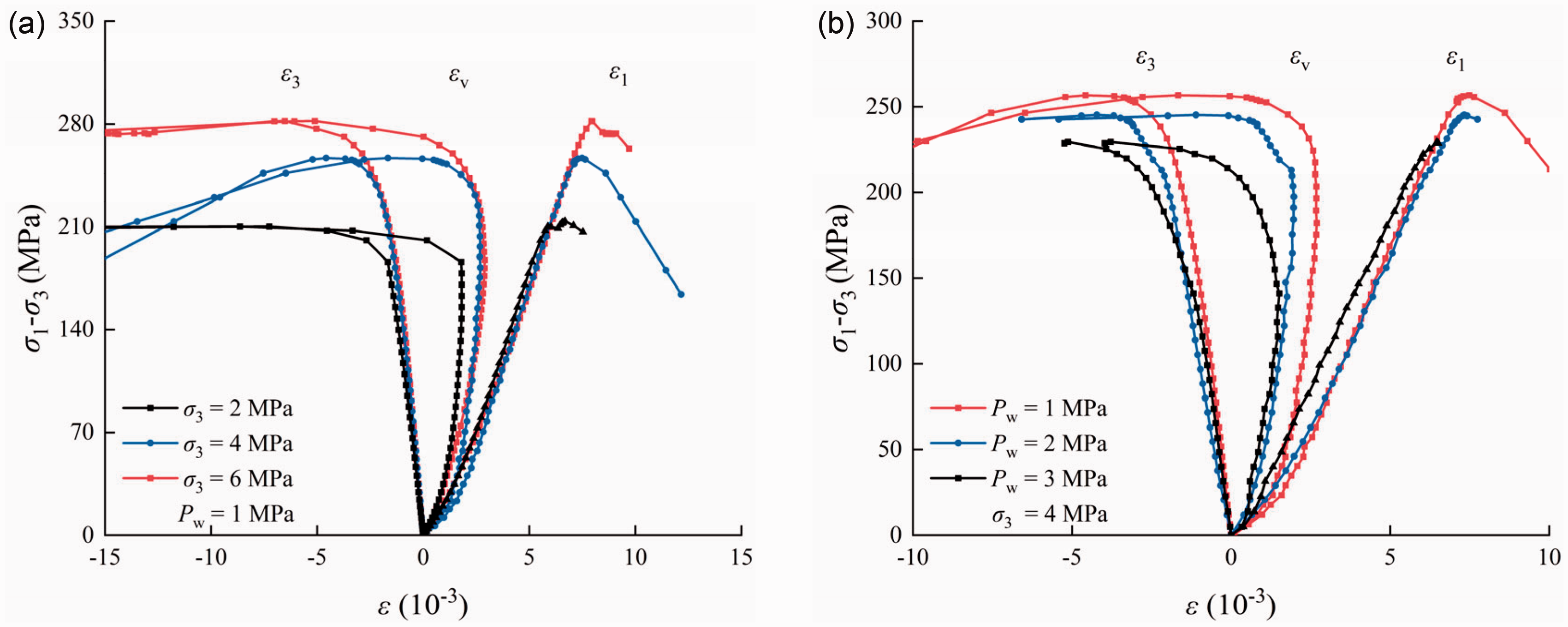
Stress–strain curves of granite under different triaxial stress conditions. (a) At same Pw (1 MPa) and different σ3 (2, 4, 6 MPa) and (b) at same σ3 (4 MPa) and different Pw (1, 2, 3 MPa).
Permeability evolution of granite under triaxial compression
Figures 5 and 6 characterizes the axial strain and permeability evolution characteristics of granite under different triaxial stress conditions. In the initial compaction stage of the granite, the fractures inside the granite are compacted or closed under the compression action of deviator stress σ1–σ3, the seepage channel is blocked, and the permeability gradually decreases. Comparing Figures 5 and 6, the influence of seepage pressure Pw on granite permeability at the initial stage of loading is less than that of confining pressure σ3. With a further increase in the deviator stress σ1–σ3, the permeability of the granite gradually decreases. When granite is in the initial stage of stable crack propagation, the permeability tends to the minimum, and the high confining pressure will increase the initial compaction degree of granite, resulting in a weaker decrease in permeability. In the stage of stable crack propagation, the generation and closure of cracks in the granite are in a relatively stable state, and the permeability is basically stable. During the stage of unstable crack propagation, microcrack generation and propagation in the rock intensify, leading to increased volume strain and the generation of numerous seepage channels. This is illustrated in Figures 7–10, and results in a significant increase in granite permeability. Figures 5 and 6 demonstrate that when the seepage pressure Pw remains constant, the plastic deformation capacity and strength of granite improve with an increase in confining pressure σ3. The greater the strain when the permeability of granite suddenly changes, the lower the corresponding permeability at the inflection point. When the confining pressure σ3 is the same, the larger the seepage pressure Pw is, the smaller the strain at the permeability mutation point, and the higher the permeability.
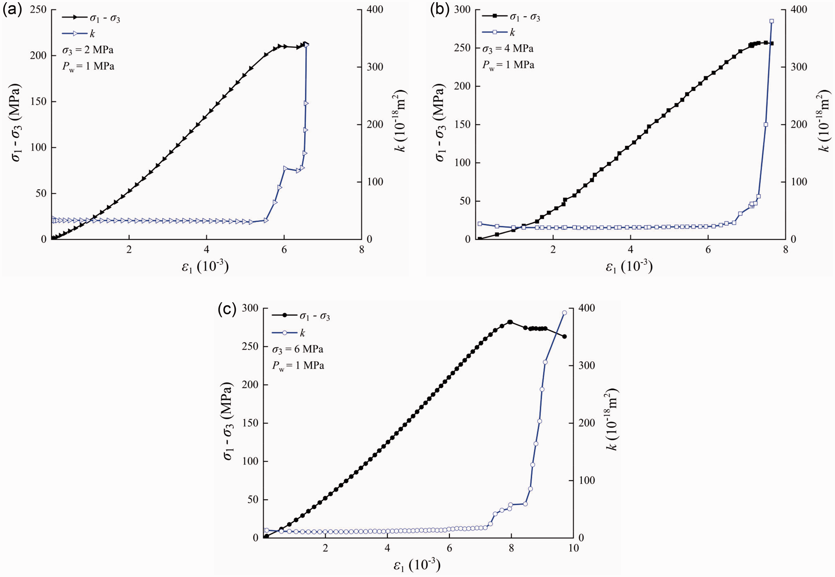
The axial strain and permeability evolution characteristics of granite under the same Pw (1 MPa) and different σ3 (2, 4, 6 MPa). (a) σ3 = 2 MPa, Pw = 1 MPa; (b) σ3 = 4 MPa, Pw = 1 MPa and (c) σ3 = 6 MPa, Pw = 1 MPa.
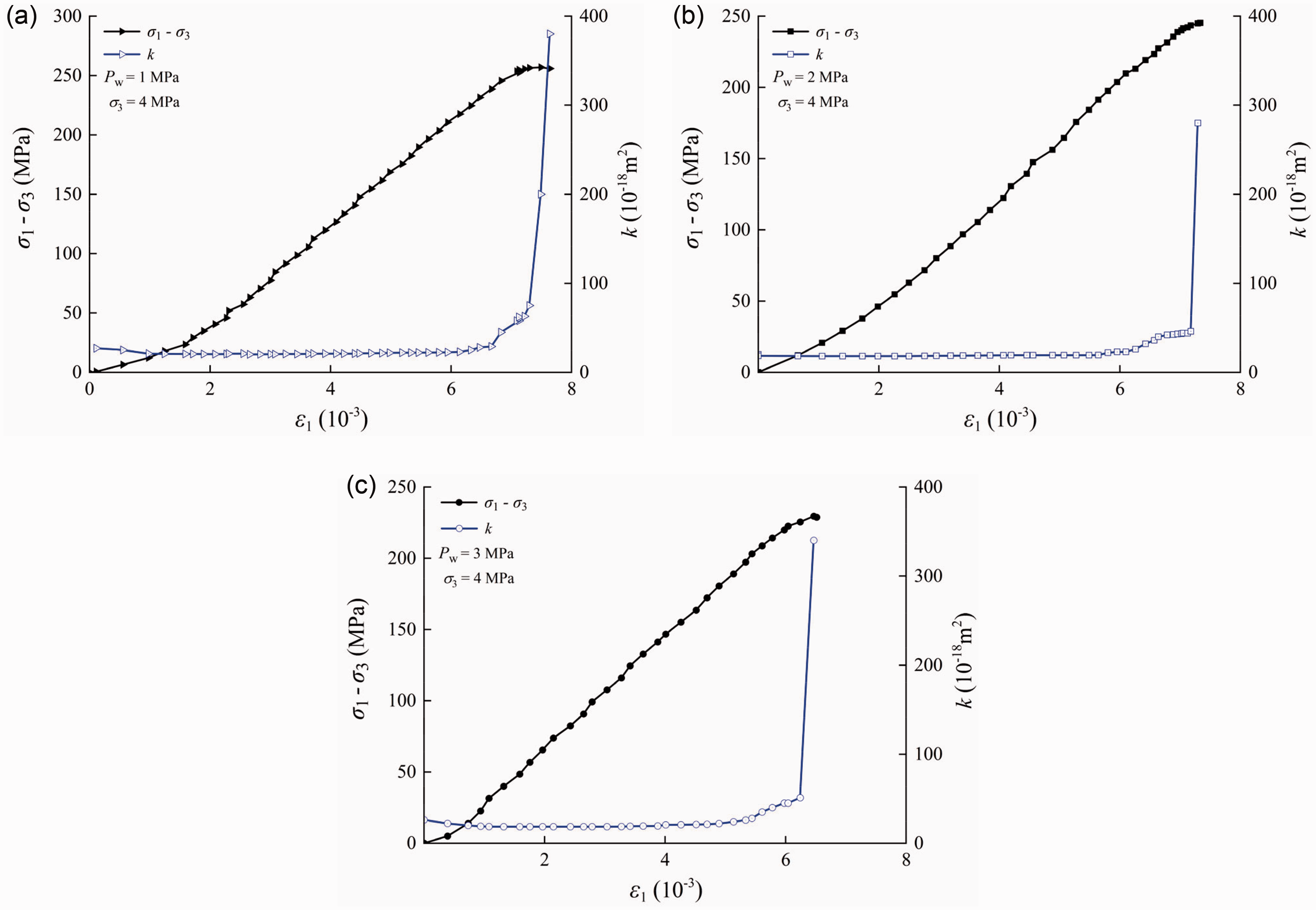
The axial strain and permeability evolution characteristics of granite under the same σ3 (4 MPa) and different Pw (1, 2, 3 MPa). (a) σ3 = 4 MPa, Pw = 1 MPa; (b) σ3 = 4 MPa, Pw = 2 MPa and (c) σ3 = 4 MPa, Pw = 3 MPa.
The lateral strain and permeability evolution characteristics of granite under the same Pw (1 MPa) and different σ3 (2, 4, 6 MPa). (a) σ3 = 2 MPa, Pw = 1 MPa; (b) σ3 = 4 MPa, Pw = 1 MPa and (c) σ3 = 6 MPa, Pw = 1 MPa.
The lateral strain and permeability evolution characteristics of granite under the same σ3 (4 MPa) and different Pw (1, 2, 3 MPa). (a) σ3 = 4 MPa, Pw = 1 MPa; (b) σ3 = 4 MPa, Pw = 2 MPa and (c) σ3 = 4 MPa, Pw = 3 MPa.
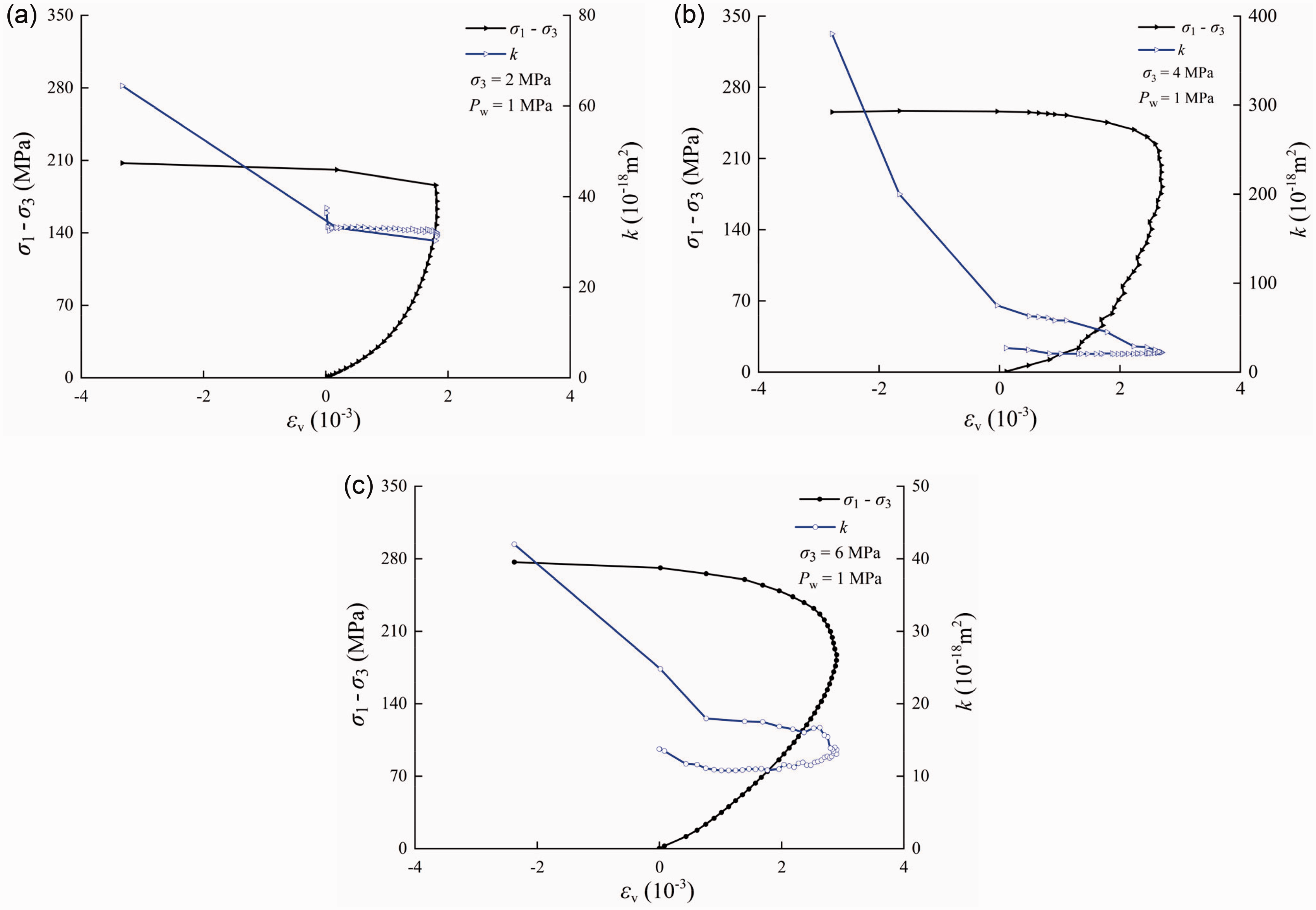
The volume strain and permeability evolution characteristics of granite under the same Pw (1 MPa) and different σ3 (2, 4, 6 MPa). (a) σ3 = 2 MPa, Pw = 1 MPa; (b) σ3 = 4 MPa, Pw = 1 MPa and (c) σ3 = 6 MPa, Pw = 1 MPa.
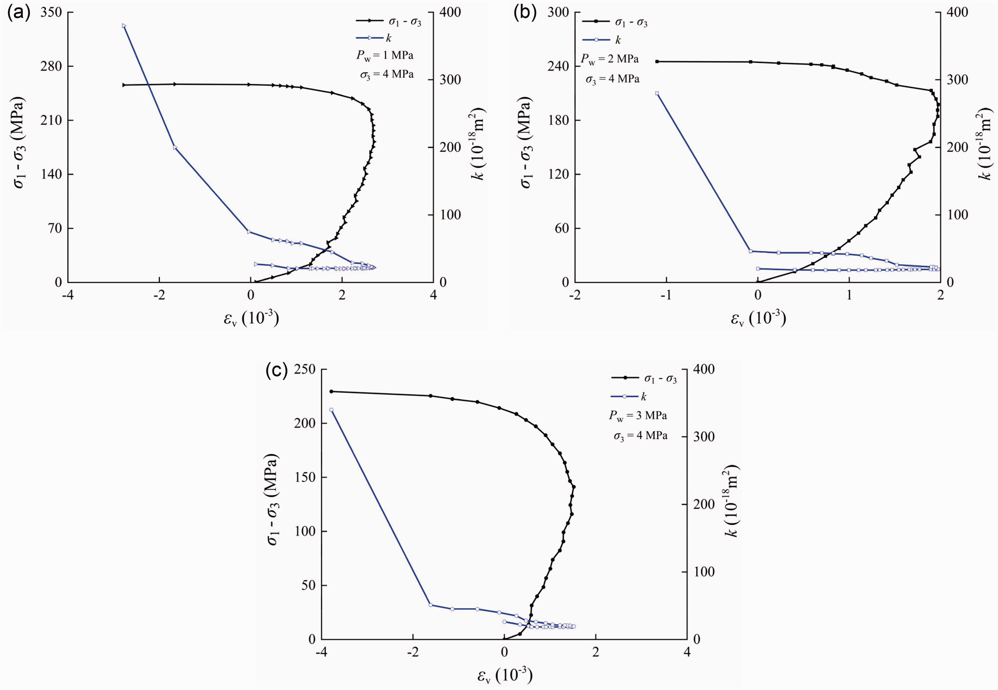
The volume strain and permeability evolution characteristics of granite under the same σ3 (4 MPa) and different Pw (1, 2, 3 MPa). (a) σ3 = 4 MPa, Pw = 1 MPa; (b) σ3 = 4 MPa, Pw = 2 MPa and (c) σ3 = 4 MPa, Pw = 3 MPa.
Test results and analysis under triaxial unloading confining pressure
Stress–strain curve characteristics of granite under triaxial unloading confining pressure
The stress–strain curve of the granite under triaxial unloading confining pressure test is shown in Figure 11. Figure 11 shows that when the confining pressure σ3 is unloaded, the axial stress σ1 remains unchanged, the granite stress–strain curve has an obvious turning point, and the turning point is consistent with the unloading point. Because the test stress paths before and after unloading are different, the deformation characteristics of granite are significantly different. The early stage of the test is a triaxial compression path, and the stress–strain of the granite is similar with that described in section 3.1. In the initial stage of confining pressure unloading, the deformation of granite is mainly lateral deformation and volume deformation, and the axial deformation is small. The stage is transformed into the expansion stage. As shown in Figure 12, the lateral deformation of the granite gradually increases at a small rate and has a good linear relationship with the confining pressure; that is, in the elastic deformation stage, no plastic deformation occurs. As the confining pressure decreases further, the slope of the lateral strain curve begins to decrease gradually, and the lateral deformation and confining pressure transform into a nonlinear relationship; that is, plastic deformation and damage occur inside the granite. When the confining pressure is unloaded to a certain level, the lateral strain increases sharply in a horizontal manner, the granite is suddenly damaged, and there is no obvious precursor before failure, indicating that the granite is more brittle when the confining pressure is unloaded.
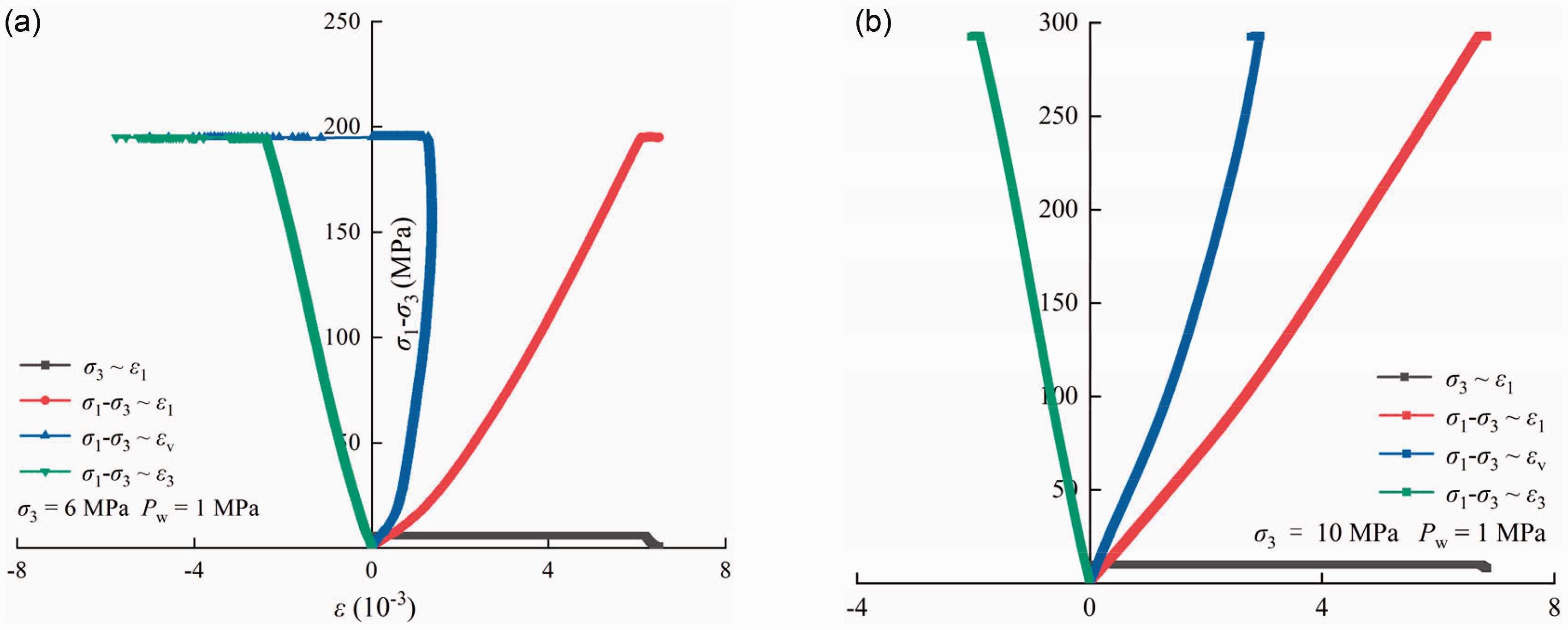
Stress–strain curves of granite under triaxial unloading confining pressure test. (a) Pw = 1 MPa, σ3 = 6 MPa and (b) Pw = 1 MPa, σ3 = 10 MPa.
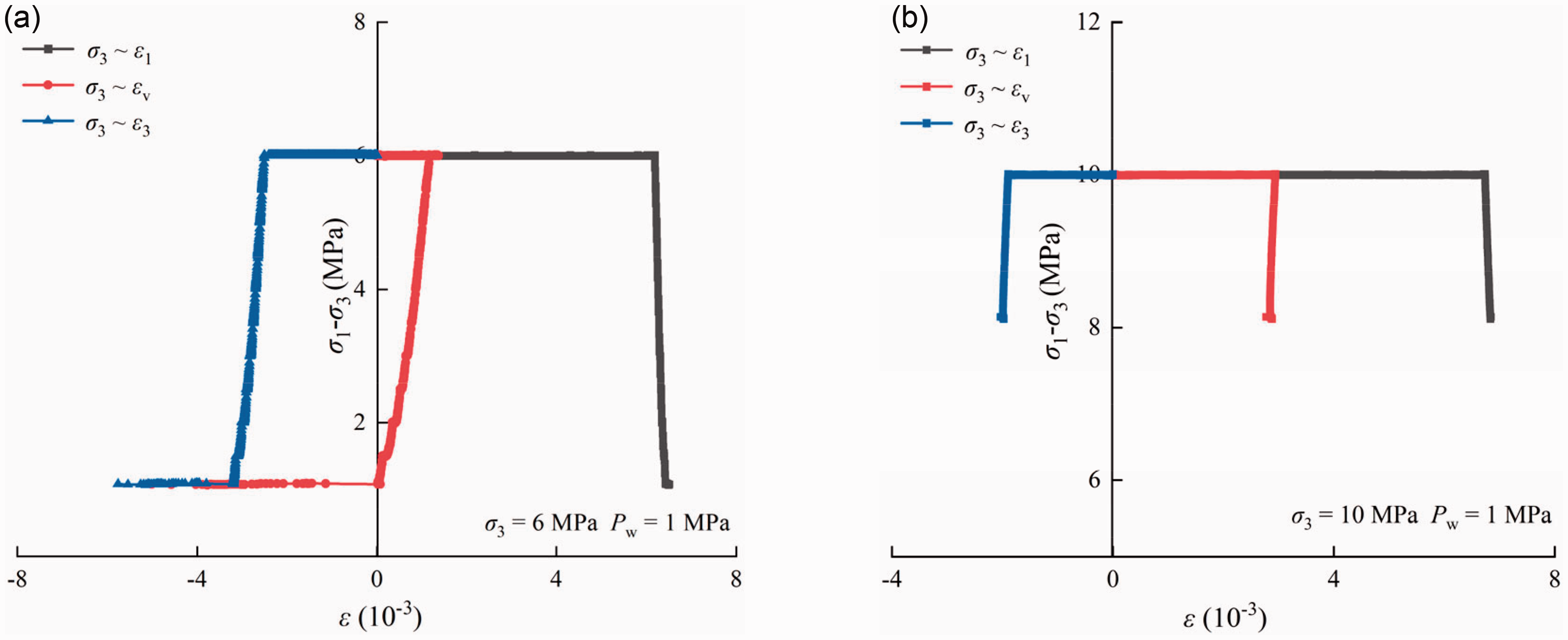
Relationship between confining pressure and strain under triaxial unloading confining pressure test. (a) Pw = 1 MPa, σ3 = 6 MPa and (b) Pw = 1 MPa, σ3 = 10 MPa.
Permeability evolution of granite under triaxial unloading confining pressure
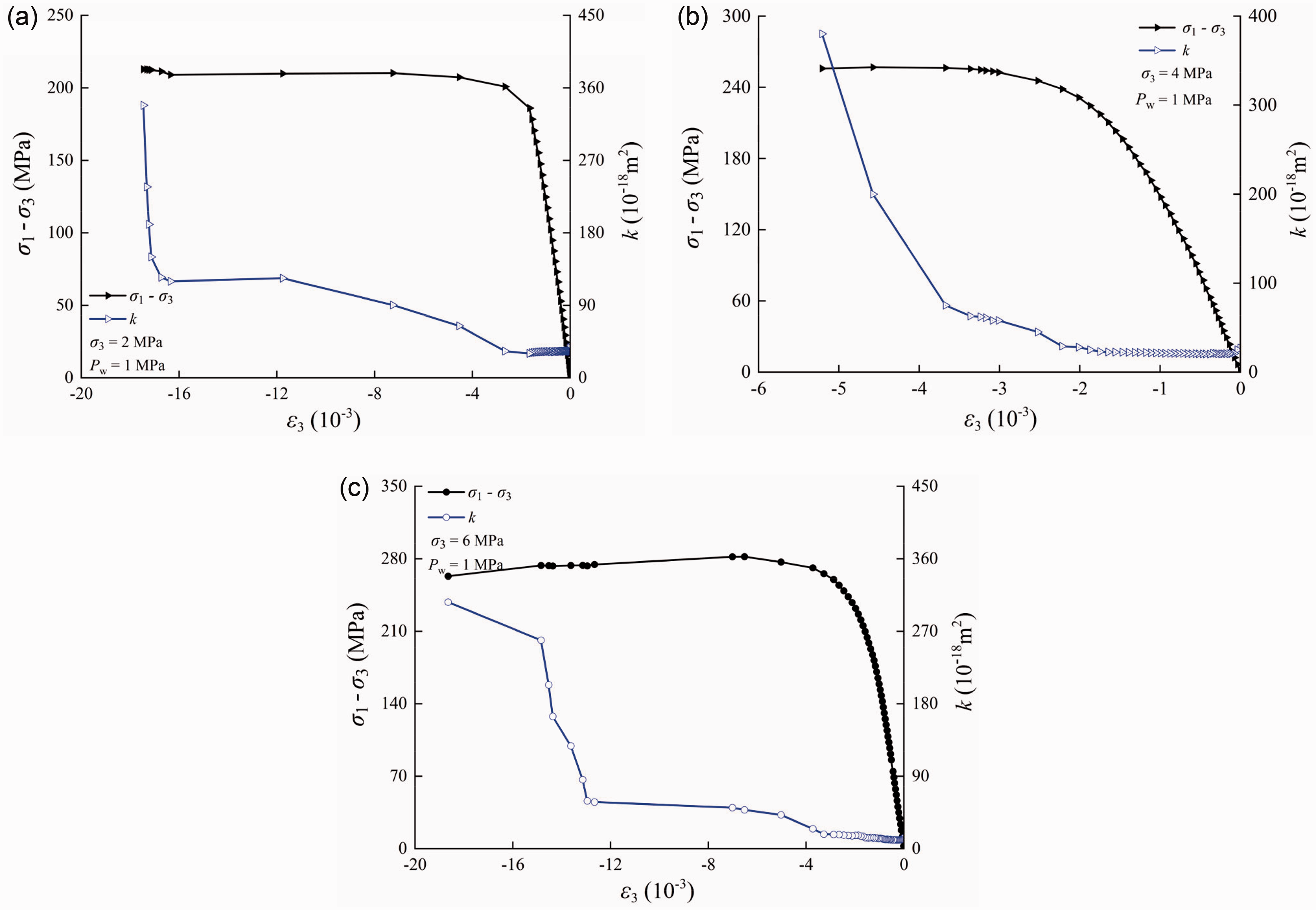
Figure 13 shows the evolution characteristics of axial strain and permeability of granite under triaxial unloading confining pressure. The permeability is closely related to the stress state of the granite. According to its changing trend, it can be divided into the following three main characteristic stages: the axial stress loading with constant confining pressure stage, keeping axial stress constant and unloading confining pressure stage and granite unloading failure stage.
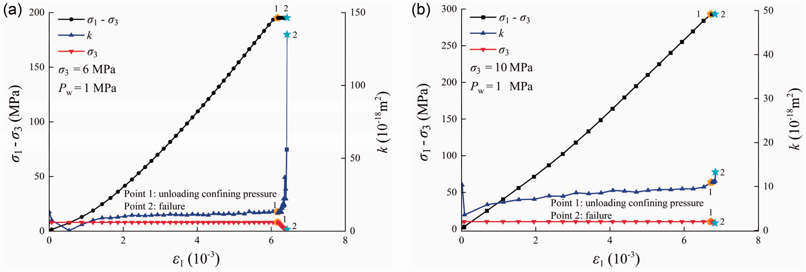
Evolution characteristics of axial strain and permeability of granite under triaxial unloading confining pressure. (a) Pw = 1 MPa, σ3 = 6 MPa and (b) Pw = 1 MPa, σ3 = 10 MPa.
Evolution characteristics of lateral strain and permeability of granite under triaxial unloading confining pressure. (a) Pw = 1 MPa, σ3 = 6 MPa and (b) Pw = 1 MPa, σ3 = 10 MPa.
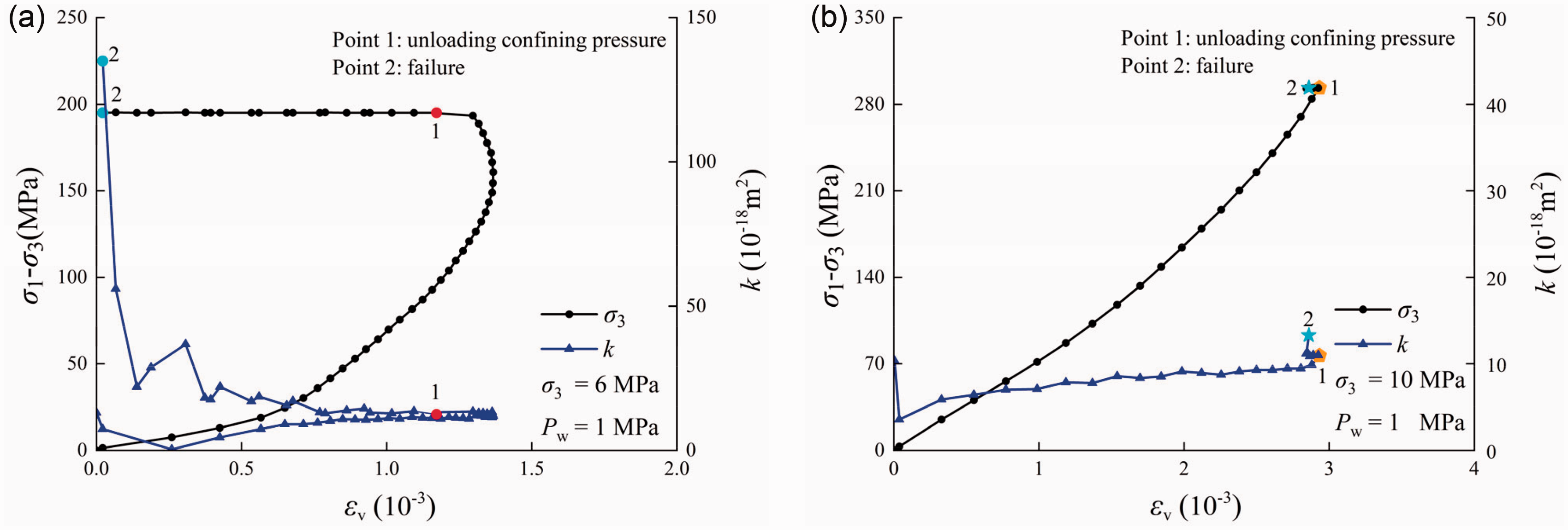
Evolution characteristics of volume strain and permeability of granite under triaxial unloading confining pressure. (a) Pw = 1 MPa, σ3 = 6 MPa and (b) Pw = 1 MPa, σ3 = 10 MPa.
The axial stress loading with constant confining pressure stage: Before the confining pressure is unloaded, it is subjected to triaxial compression, and its characteristics are the same as those of the triaxial test. In the initial loading stage of axial stress σ1, the internal microcracks and pores of the rock specimen are compacted and closed, the microcracks of the primary pores decrease, and the permeability decreases rapidly with increasing axial stress. As the axial loading level continues to increase, new microcracks begin to appear inside the rock specimen, and at the same time, the microcracks in the primary pores continue to be compressed, and the decreasing trend of permeability becomes slower. When the crack development and compression balance, the granite permeability is stable; at the same time, the confining pressure σ3 has a restraining effect on the crack development, and the permeability of the rock specimen with a confining pressure of 10 MPa is less than that of the rock specimen with a confining pressure of 6 MPa.
Keeping axial stress constant and unloading confining pressure stage: before granite failure, the permeability of granite gradually increases with the unloading of confining pressure, but the increase is small, which is related to σ3. When the granite is near to failure, the permeability increases more obviously, the granite permeability under low confining pressure has an obvious increase section, and the increase amplitude is also more obvious. From Figure 13(a), it can be seen that the initial rock of unloading confining pressure is still in the elastic stage or the stage of stable crack development. At this stage, the generation of new cracks and the closure of primary cracks inside granite are in dynamic equilibrium, and the granite permeability is stable. When the confining pressure is further unloaded, the new cracks inside the granite increase, resulting in an increase in the permeability of the granite during the process of unloading the confining pressure. When the granite is near to failure, a large number of internal cracks are generated, expanded and penetrated, and its permeability has a greater increase, even mutation phenomenon occurs. Because the unloading of the granite under high confining pressure makes it more brittle and the failure occurs more suddenly, the permeability increase section of the high confining pressure rock specimen is short and does not increase significantly, as shown in the permeability curve in Figure 13(b). The on-site excavation process in the reservoir area is similar to this stage. During the excavation process of the underground chamber, the horizontal stress in front of the excavation front is continuously unloaded and reduced, and the bearing capacity of the granite gradually increases to the limit, which reflects the change rule of reservoir permeability during excavation.
Rock unloading failure stage: the axial stress remains unchanged. With the confining pressure unloading, the bearing capacity of the granite gradually decreases. When the confining pressure is unloaded to a certain level, the stress on the granite reach its ultimate bearing capacity, and failure occurs. At this time, the permeability of the rock specimen increases sharply. Figures 13 to 16 show that when granite failure, its permeability changes abruptly, which is hundreds or even thousands of times that before the damage. This is because at this stage, a large number of pores and fissures are generated, expanded and penetrated inside the granite due to the macro damage, and even a macroscopic fracture surface is formed, which is transformed into fissure seepage. This is one of the main reasons for leakage in the process of cavern excavation and coal seam mining.
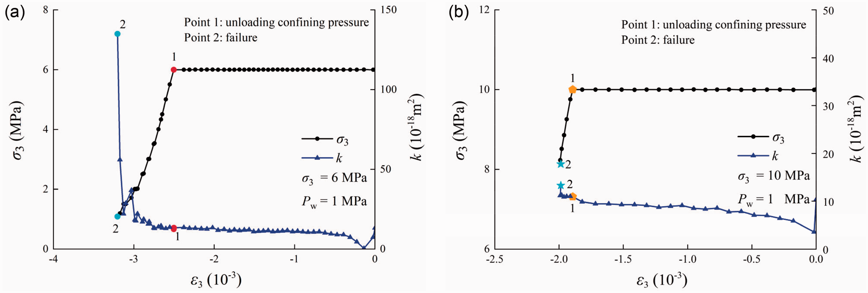
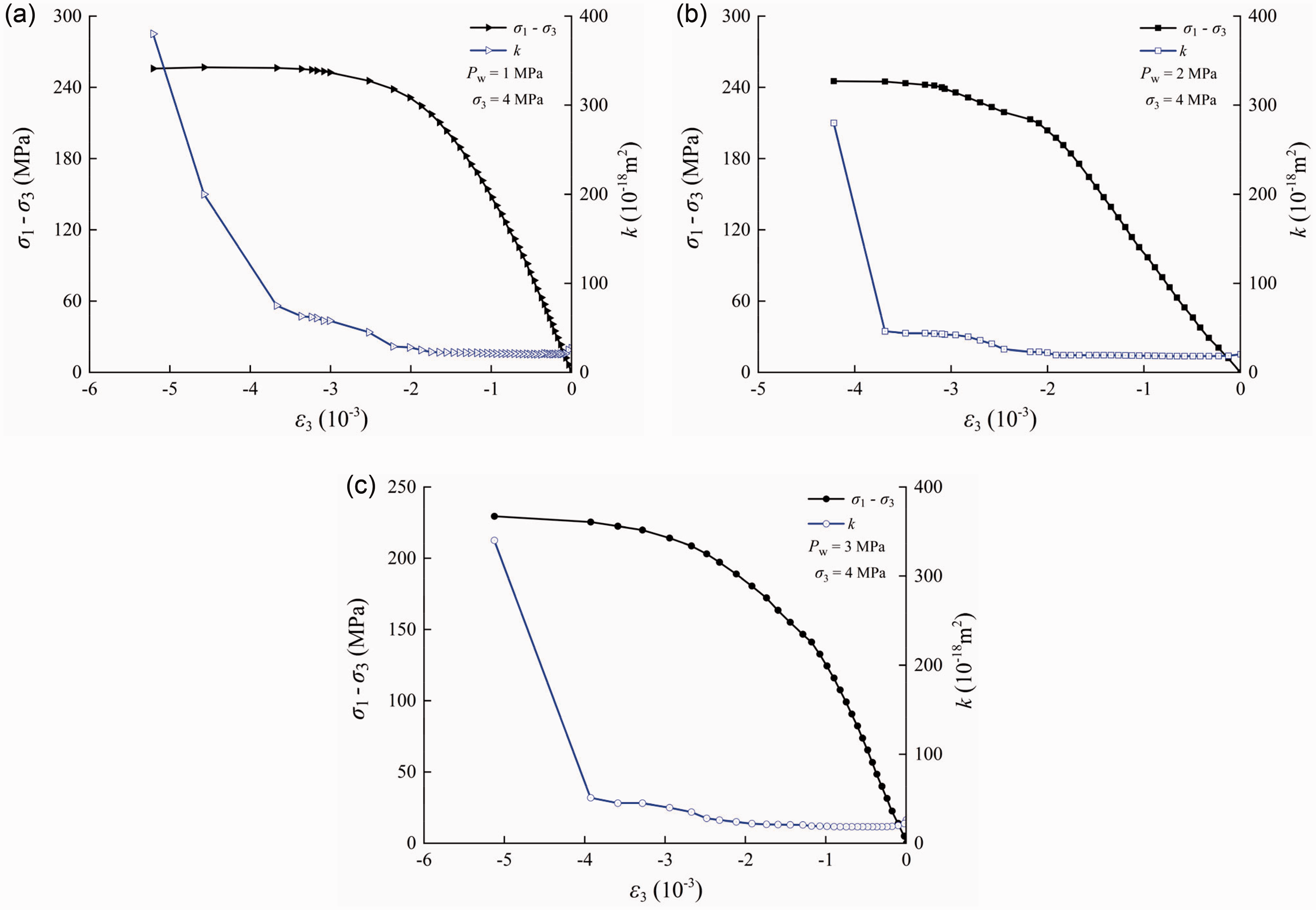
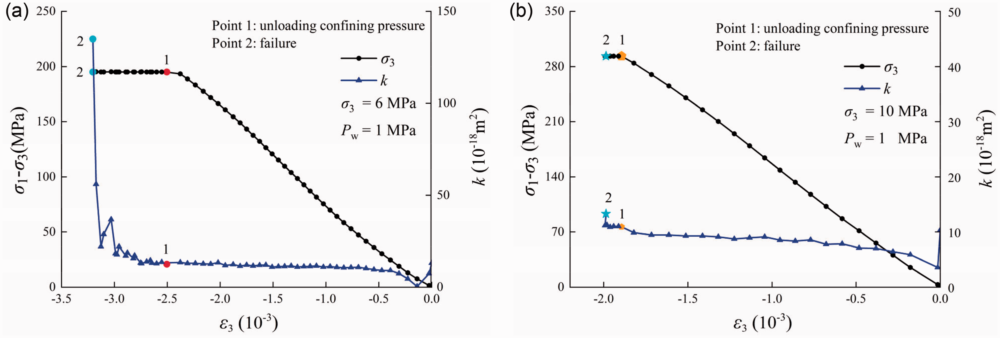
The relationship between permeability, confining pressure and lateral strain of granite under triaxial unloading confining pressure. (a) Pw = 1 MPa, σ3 = 6 MPa and (b) Pw = 1 MPa, σ3 = 10 MPa.
Test results and analysis under triaxial cyclic loading and unloading
Stress–strain curve characteristics of granite under triaxial cyclic loading and unloading
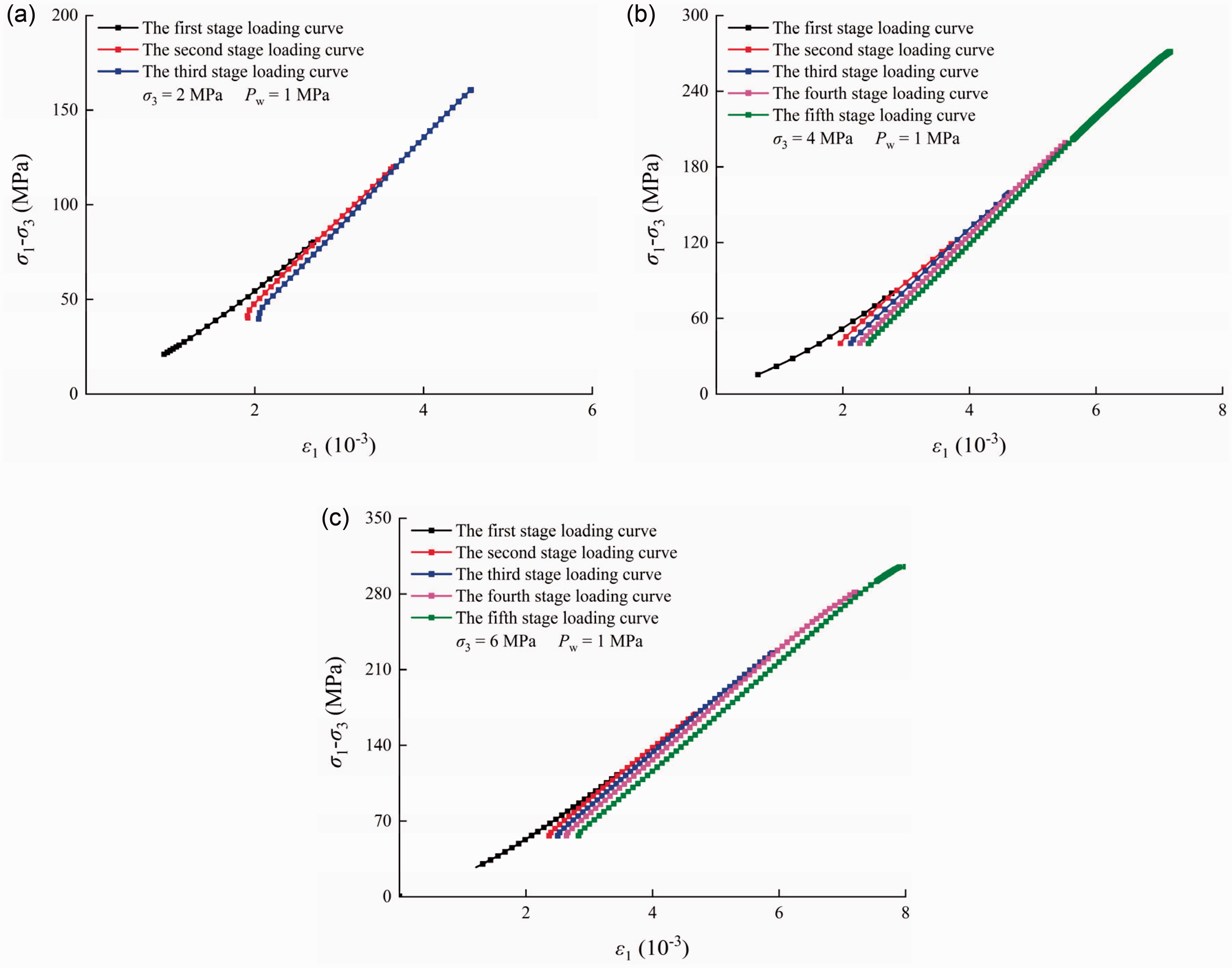
Figure 17 is the stress–strain curves of granite under triaxial cyclic loading and unloading tests. It can be seen from Figure 17 that due to the memory of granite deformation, the stress–strain curve of granite under triaxial cyclic loading and unloading still rises along the original triaxial compression test curve. In the test, the loading curves of all levels have almost the same regularity, and they all have straight line segments and curved segments at both ends. The slope of the loading and unloading curve of the first stage is obviously smaller than that of the other stages, and the slope of the loading curve of the subsequent stages is basically unchanged. With the increase of stress, microcracks in the granite are generated and expanded, and the plastic strain gradually increases, resulting in the hysteresis loops of axial strain, lateral strain and volume strain under various stress conditions, all of which appear with the increase of axial compression load level appear forward migration situation. The nonlinear starting point of the deviatoric stress-lateral strain test curve is obviously lower than the damage strength. During the loading and unloading stage of granite stress, the lateral strain enters the nonlinear stage earlier, and the lateral plastic strain accumulates continuously. The increase of lateral plasticity leads to a large increase of lateral strain. Compared with the axial strain, the plastic degree of the lateral strain is larger, resulting in the migration of the hysteresis loop of the lateral strain. In addition, the volume strain increases more than the axial deformation. Before the inflection point of granite expansion, the migration degree of the hysteresis loop is small. After the inflection point, the granite enters the crack expansion stage, the cracks in the granite are interconnected, the plastic deformation increases rapidly, and the migration degree of the strain hysteresis loop intensifies. With increasing σ3, the deformation of the granite is greatly constrained, the peak strength increases, and the migration degree of the hysteresis loop is gradually weakened.
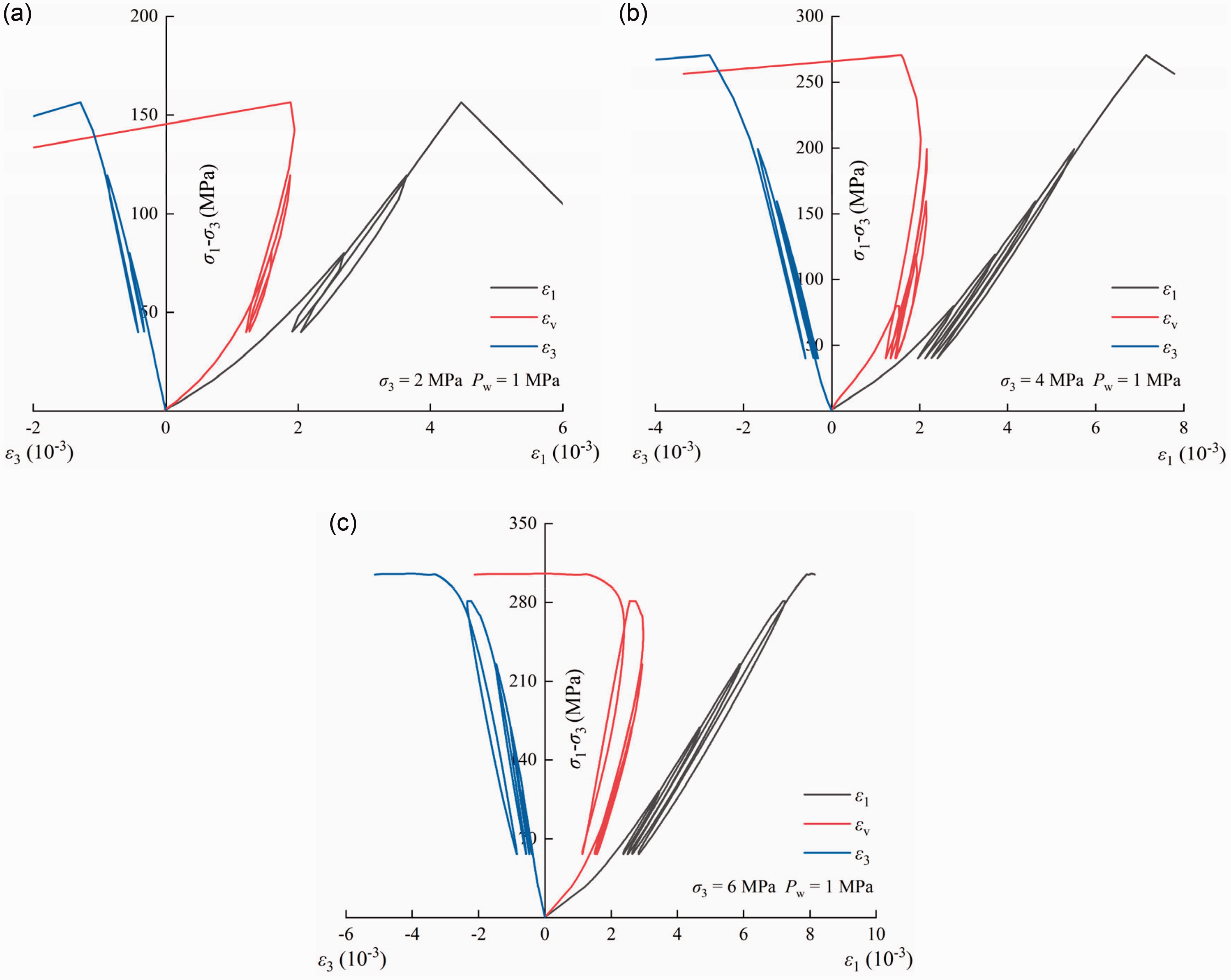
Stress–strain curves of granite under triaxial cyclic loading and unloading tests. (a) Pw = 1 MPa, σ3 = 2 MPa; (b) Pw = 1 MPa, σ3 = 4 MPa and (c) Pw = 1 MPa, σ3 = 6 MPa.
Permeability evolution of granite under triaxial cyclic loading and unloading
Figure 19 shows the evolution characteristics of volume strain and permeability of granite under triaxial cyclic loading and unloading conditions. When the σ3 is 2 MPa, the axial compression cyclic loading and unloading loads are all before the volume strain turning stress. When the σ3 is 4 MPa, the axial compression cyclic loading and unloading loads rise to the same level as the volume strain turning stress. When the σ3 is 6 MPa, the axial maximum load of compressive cyclic loading and unloading has exceeded the volume strain transition stress. Figure 19 shows that the permeability of granite is relatively stable when it is in the previous stage of expansion, and there is no obvious change. The corresponding permeability decreases for a short time and then tends to be stable again, while the granite permeability increases in the corresponding stress unloading stage, and the permeability of each stress unloading stage does not change much and is approximately at the same level. In addition, similar to the strain hysteresis loop, the permeability of the granite also has similar changes during the loading and unloading stages of the axial compression cycle at different stress levels, that is, the permeability hysteresis loop is generated. Figures 19(a) and (b) show that when the stress loading is before the volume turning stress level, the permeability hysteresis loop formed by the granite is relatively complete, but after the volume turning stress level, the granite permeability increases greatly in the stress loading stage. Although the permeability decreases in the stress unloading stage, it is still larger than the initial permeability corresponding to the cyclic loading point. In addition, it can be seen from Figure 20 that the internal cracks of granite under load are closed and the permeability is lower than that during unloading.
Figures 18 to 20 show that in the initial stage of stress loading, the granite is in the compaction stage and the linear elastic stage, and the primary fractures inside the granite are closed by compression; the granite permeability only slightly decreases. When the cracks are in the stable development stage, the original cracks are compacted, new cracks develop at the same level, and the granite permeability is stable, which is consistent with the triaxial compression properties. When the stress is unloaded, the pores and cracks closed in the previous stage are released again, and the permeability increases due to the increase in channels. As the load level exceeds the volume strain transition stress of the granite, the granite enters the expansion stage, and the permeability increases greatly in both the loading stage and the unloading stage. When unloading to the lowest stress level, the permeability is still greater than the initial permeability in the loading stage. This is because the stress load level is relatively large, the granite produces irreversible plastic strain, a large number of internal cracks are initiated and penetrated, and the seepage channels increase, which is far greater than the crack closure of the granite in the compaction stage and the linear elastic stage. The internal fissures are only closed to a certain extent, and the original closed state cannot be restored. There is a close relationship between granite permeability and granite volume strain. When the granite is in the compression stage, the granite permeability first decreases to a stable state. Before expansion, the granite permeability is approximately stable, and the granite permeability increases rapidly during the expansion stage. The critical stress of volume strain expansion can be used as an indicator of permeability change.
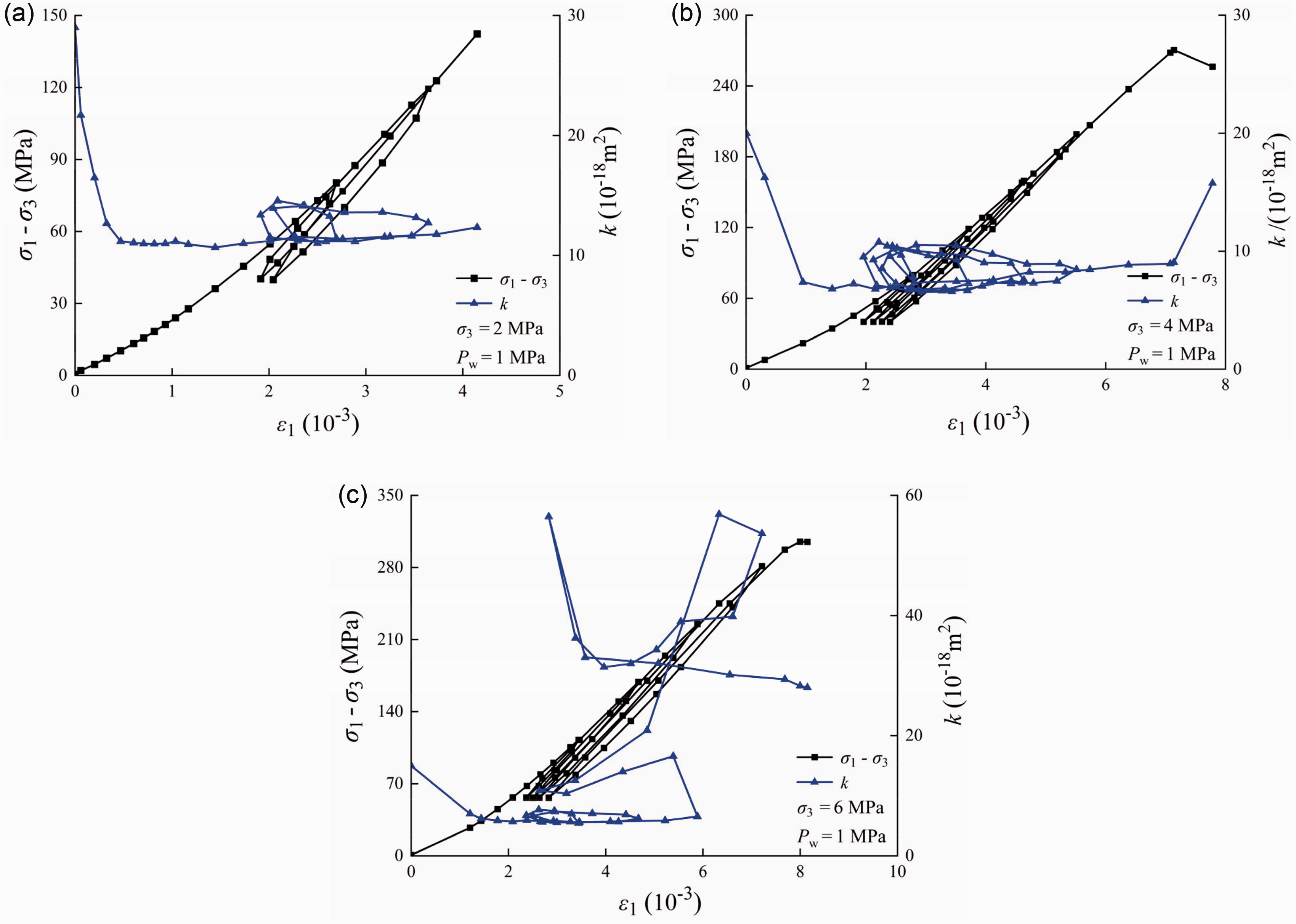
Evolution characteristics of axial strain and permeability of granite under triaxial cyclic loading and unloading under. (a) σ3 = 2 MPa, Pw =1 MPa; (b) σ3 = 4 MPa, Pw = 1 MPa and (c) σ3 = 6 MPa, Pw = 1 MPa.
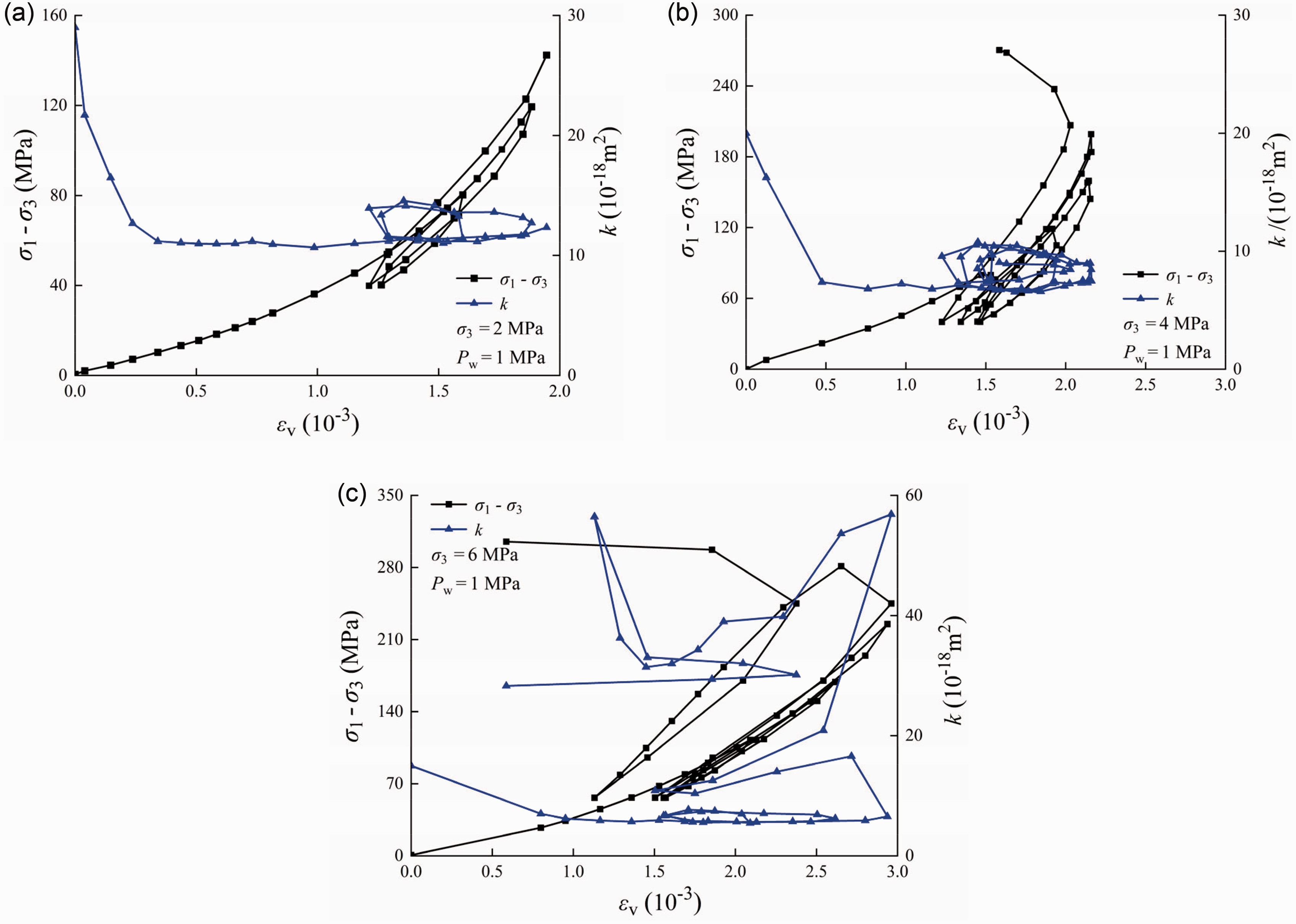
Evolution characteristics of volume strain and permeability of granite under triaxial cyclic loading and unloading conditions. (a) σ3 = 2 MPa, Pw =1 MPa; (b) σ3 = 4 MPa, Pw = 1 MPa and (c) σ3 = 6 MPa, Pw = 1 MPa.
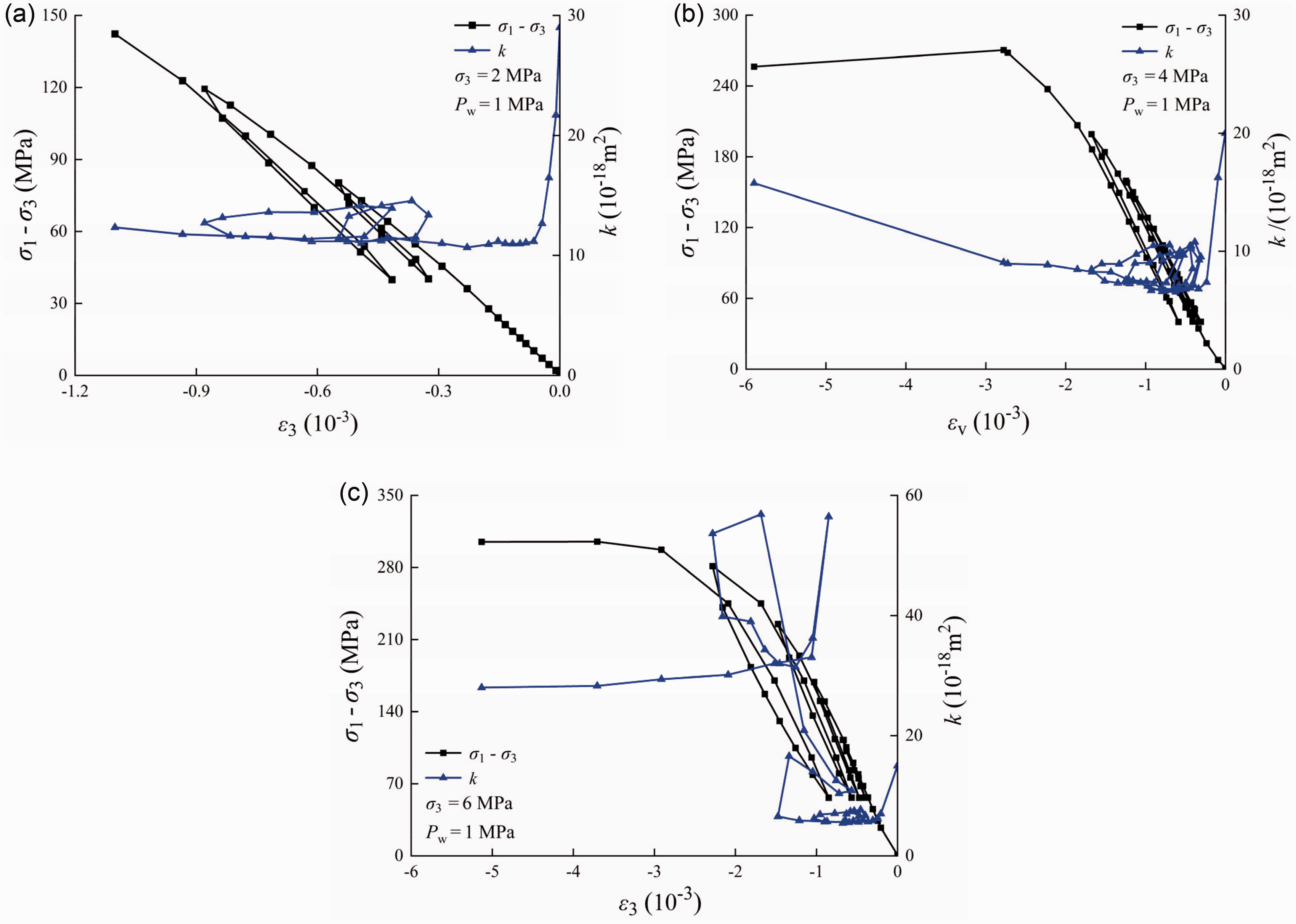
Evolution characteristics of lateral strain and permeability of granite under triaxial cyclic loading and unloading conditions. (a) σ3 = 2 MPa, Pw =1 MPa; (b) σ3 = 4 MPa, Pw = 1 MPa and (c) σ3 = 6 MPa, Pw = 1 MPa.
A new seepage-stress coupling statistical damage model
Model establishment
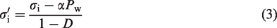
Based on Lemaitre (1984) strain equivalent theory, it can be concluded that:

Under the seepage-stress coupling effect, the expression of effective stress is (Biot, 1941):

It can be known from equations (1) and (2) that the equivalent stress under the seepage-stress coupling is:
The relationship between

Substituting equations (1) and (3) into equation (4), the seepage-stress coupling statistical damage constitutive model of rock under true triaxial stress can be rewritten as:


The rock statistical damage variable D is the ratio of the number of damaged rock micro-units Md to the total number of micro-units M in the non-destructive state (Li et al., 2012), which ranges from 0 to 1, that is,

Various defects inside the rock lead to its own destruction with great randomness. The Weibull distribution law (Tang et al., 2000; Weibull, 1951; Zheng et al., 2023d) can better reflect the random failure of rocks, and it is assumed that the probability density function of its failure is:

The failure probability can be obtained by integrating the density function:
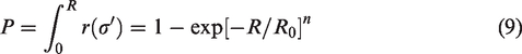
Calculate the failure number Md

Substituting equation (9) into equation (10) and then into equation (7), we can obtain:

Rock micro-element strength R is directly expressed by rock micro-element stress (Deng and Gu, 2011). Let

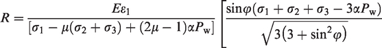
According to the transformation of Drucker-Prager strength failure criterion, R can be expressed as:


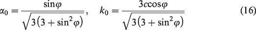
Substituting equations (3), (14) to (16) into equation (13) to yields:
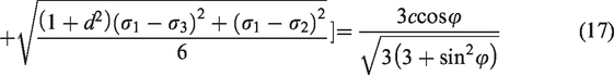
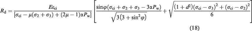
Researchers (Li et al., 2012; Wang and Ma, 2022; Zheng et al., 2022) have found that internal damage of rock will occur only when the stress applied to the rock exceeds a certain value (i.e. stress threshold). The loading stress is less than the damage threshold, and the rock is in an undamaged state, assuming that D = 0. Considering the influence of rock σ3, the σci (corresponding strain is εci) is taken as the damage threshold of rock failure, and it can be substituted into equation (17) to obtain the threshold micro-element strength Rd of different stress states.
When considering the damage threshold, equation (11) can be rewritten as:
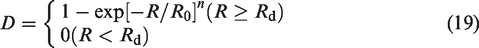
Substituting equation (19) into equation (5), The statistical damage constitutive model of seepage-stress coupling based on Drucker-Prager criterion can be obtained considering the Rd:

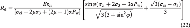
For the triaxial compression test, when σ2 = σ3 and d = 0, equations (17) and (18) degenerate into

In order to better simulate the curve shape of the rock at the initial stage of loading and compaction, the compaction coefficient C is used to fit the early stage of the stress–strain curve.

Determination method of model parameters
It can be seen from Section 6.1 that parameters n and R0 follow Weibull distribution. When R ≥ Rd, change equation (24) to fit the experimental data:

Mathematical operation on equation (25) can obtain:


Model test verification
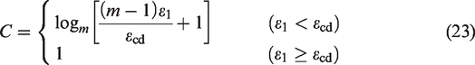
In the process of loading, the damage of rock increases continuously. In order to verify the rationality of the model, the parameters n and R0 are obtained by fitting the experimental data, and the damage variable (equation (19)) is calculated and verified. The results are shown in Figure 21.
The relationship between the damage variable D (considering damage threshold) and strain ε1 under three different testing paths. (a) Triaxial compression; (b) triaxial unloading confining pressure and (c) triaxial cyclic loading and unloading.
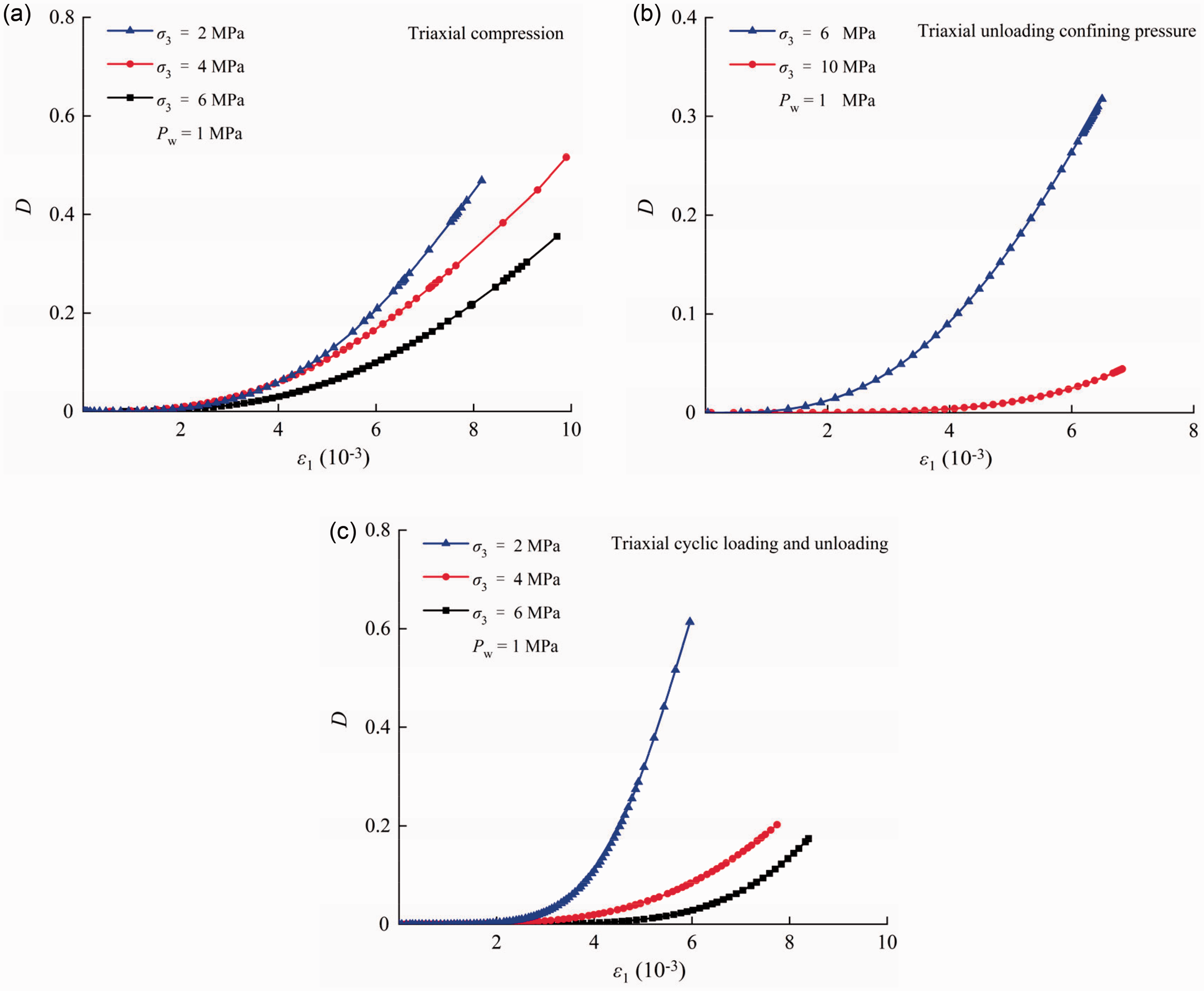
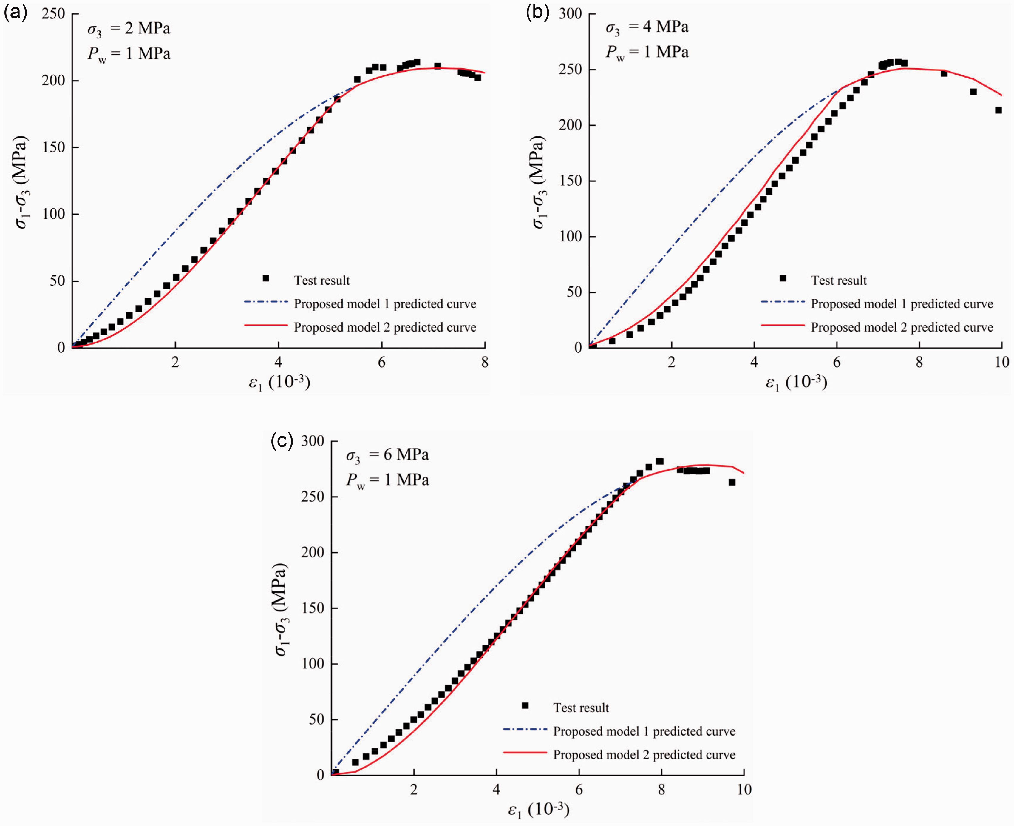
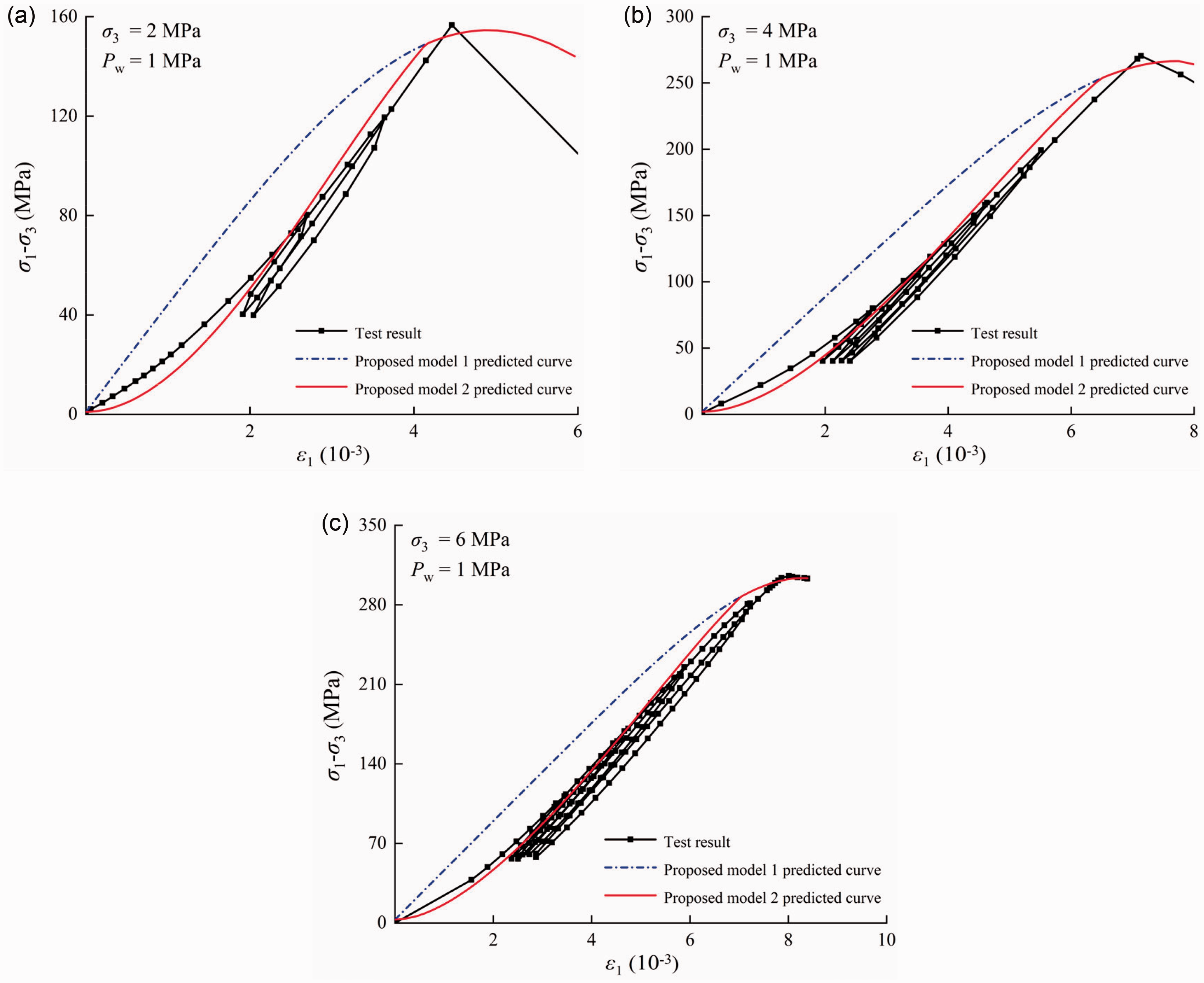
Figures 22 to 24 shows the simulation results of the two models established in Section 6.1. Model 1 (equation (20)) only considers the impact of damage threshold in the process of establishment, and the simulated curve is different from the actual test curve in the compaction stage of the rock. In order to further conform to the test results, the model 2 (equation (24)) with compaction coefficient C is consistent with the curve under three test conditions (triaxial compression test, triaxial unloading confining pressure test and triaxial cyclic loading and unloading test), and it is consistent with the progressive deformation and failure of the rock. The process is consistent, which verifies the rationality of the model.
Comparison of the proposed model prediction curves and test results of granite under triaxial compression condition. (a) σ3 = 2 MPa, Pw = 1 MPa; (b) σ3 = 4 MPa, Pw = 1 MPa and (c) σ3 = 6 MPa, Pw = 1 MPa.
Comparison of the proposed model prediction curves and test results of granite under triaxial unloading confining pressure condition. (a) σ3 = 6 MPa, Pw = 1 MPa and (b) σ3 = 10 MPa, Pw = 1 MPa.
Comparison of the proposed model prediction curves and test results of granite under triaxial cyclic loading and unloading condition. (a) σ3 = 2 MPa, Pw = 1 MPa; (b) σ3 = 4 MPa, Pw = 1 MPa and (c) σ3 = 6 MPa, Pw = 1 MPa.
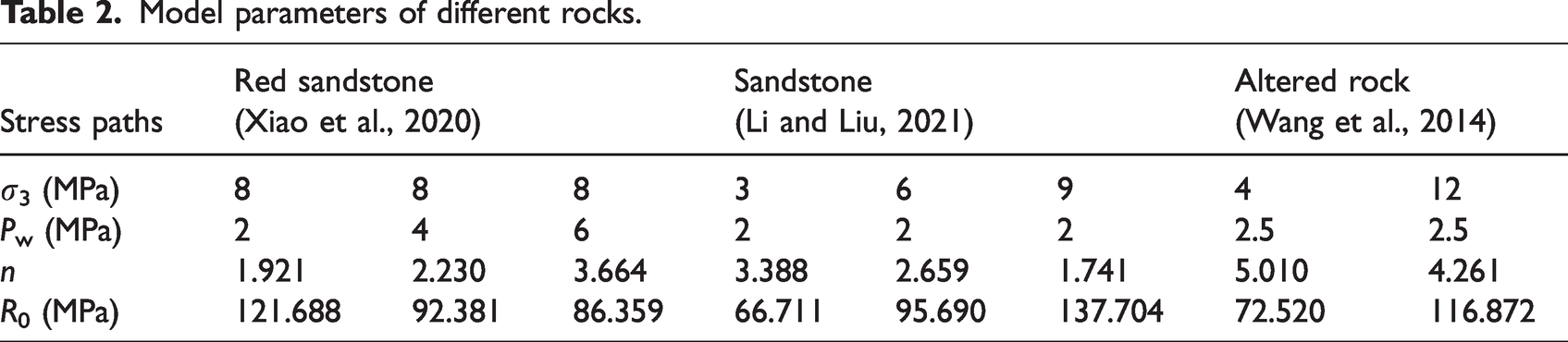
To confirm the universality of the proposed model, diverse types of rocks underwent model verification. Figure 25 presents the comparative analysis of the test curves and simulated curves for various rock types. The obtained results demonstrate that the proposed model (equation (24)) shows good simulation results the seepage stress coupling test results of red sandstone (Xiao et al., 2020), sandstone (Li and Liu, 2021), and altered rock (Wang et al., 2014), thereby providing valuable insights for exploring the seepage-stress coupling characteristics of other rock types.
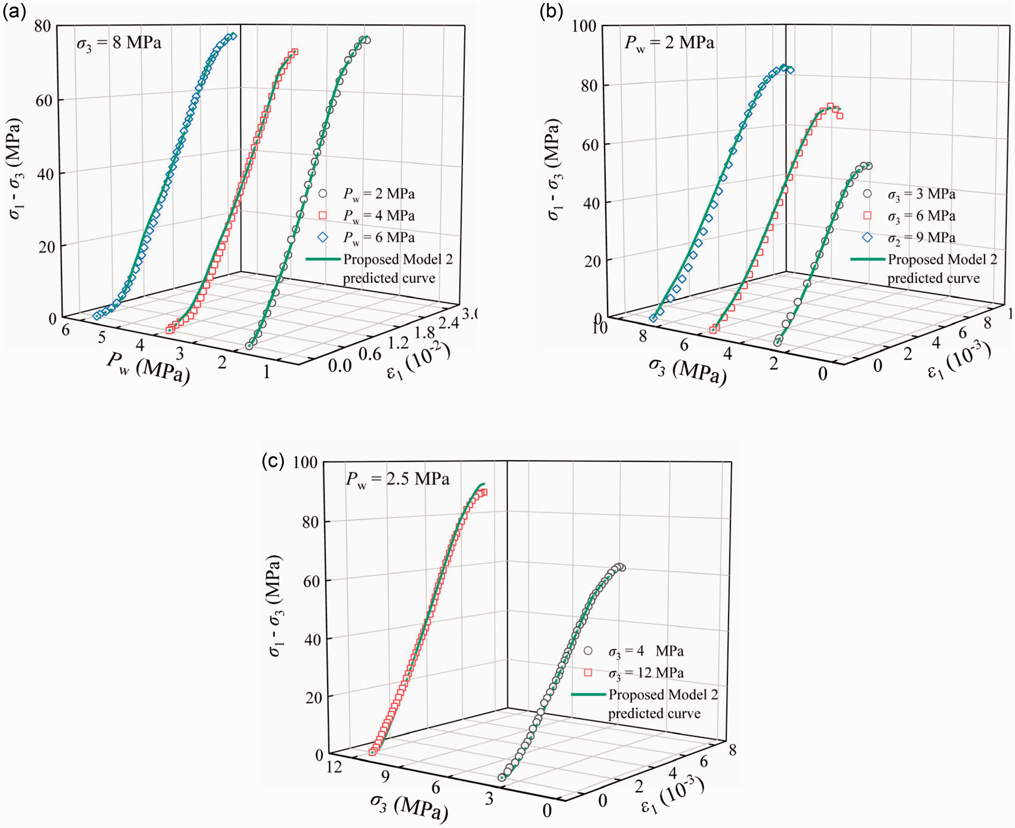
Comparison of the proposed model prediction curves and test results of different rocks under triaxial compression test. (a) Red sandstone (Xiao et al.,2020); (b) sandstone (Li and Liu, 2021); (c) altered rock (Wang et al., 2014).
Relationship between R0 and n and σeff
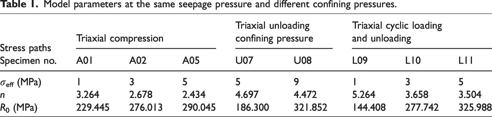
The model parameter R0 is related to the strength of the granite, and the strength of the granite increases with increasing model parameter R0. The ductility and brittleness of granite are related to the model parameter n. The smaller n is, the more discrete the microelement strength distribution of the granite is, and the greater the ductility of the rock is. Therefore, the model parameter n is also called the rock homogeneity coefficient. Researchers (Li et al., 2012) found that there was a good fitting relationship between the two groups of test data and model parameters through comparative analysis. The relationship between the model parameters R0 and n and σeff is shown in Figure 26. The model parameters R0 and n have a good correlation with σeff. Table 1 and Figure 26 show that the rock model parameters R0 and n change under the two stress paths of triaxial compression and triaxial cyclic loading and unloading. The law is roughly the same; with the increase of σeff, R0 increases linearly, and n decreases exponentially.
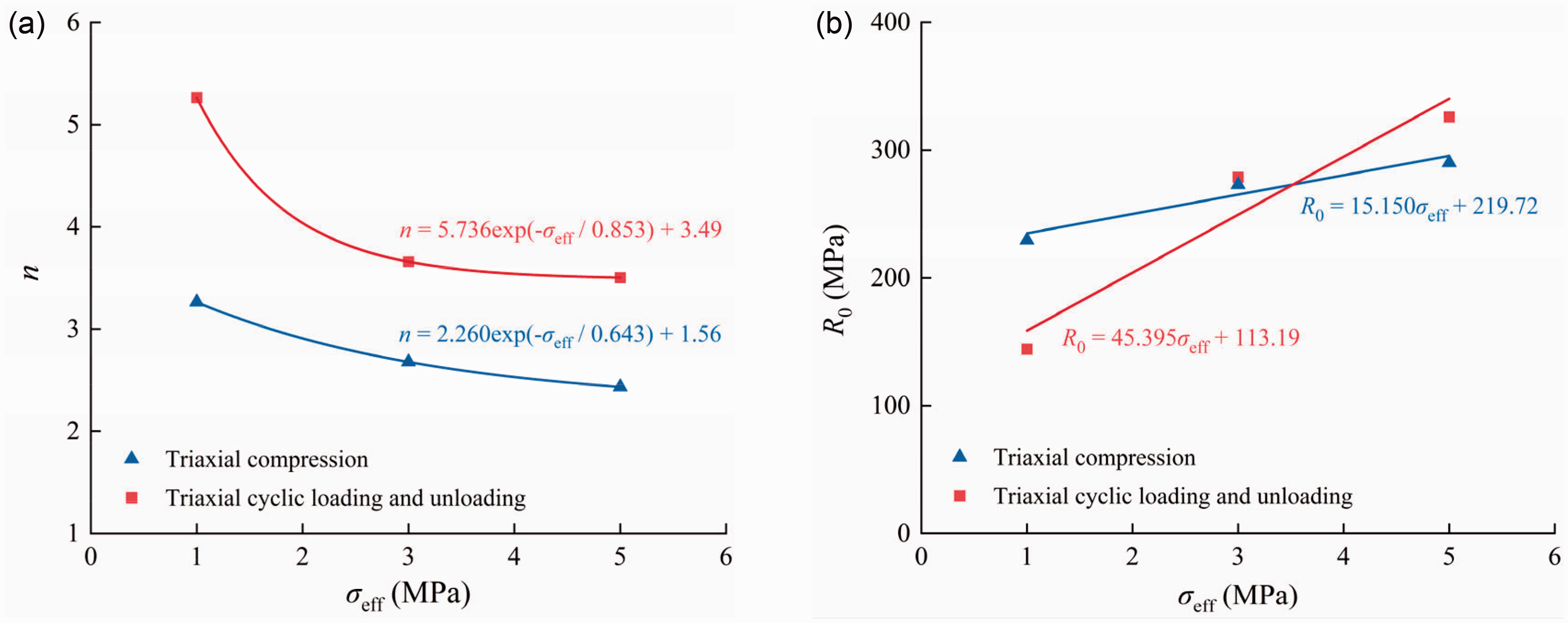
Relationships between model parameters R0, n and the effective confining pressure σeff. (a) Relationship between n and σeff and (b) relationship between R0 and σeff.
Model parameters at the same seepage pressure and different confining pressures.
Model parameters of different rocks.
Discussion
Effect of the stress paths on permeability
Figure 27 shows the relationship between the permeability and strain of granite under different stress paths when σ3 = 6 MPa and Pw = 1 MPa. From the analysis of Figure 27, it can be seen that although the stress paths of granite during loading are different, the initial permeability of granite remains basically unchanged. With further loading, there will be a small decrease, but under unloading confining pressure loading will first produce a smaller permeability. The mutation then returns to a steady state. When the permeability decreases to the minimum value, the permeability minimum value of triaxial compression loading and confining pressure unloading loading is approximately the same, while the permeability minimum value of cyclic loading and unloading is lower than that of the first two stress paths. Because of the continuous cycling during loading and unloading, the rock skeleton is compressed to drive the fractures to be further compacted. The seepage channels inside the rock are less than the first two stress paths in the stable permeability stage, and water is less permeable in the rock. The granite permeability curves under the two stress paths of triaxial compression and unloading confining pressure are roughly the same, while the permeability curves of granite under cyclic loading and unloading show multiple permeability hysteresis loops.
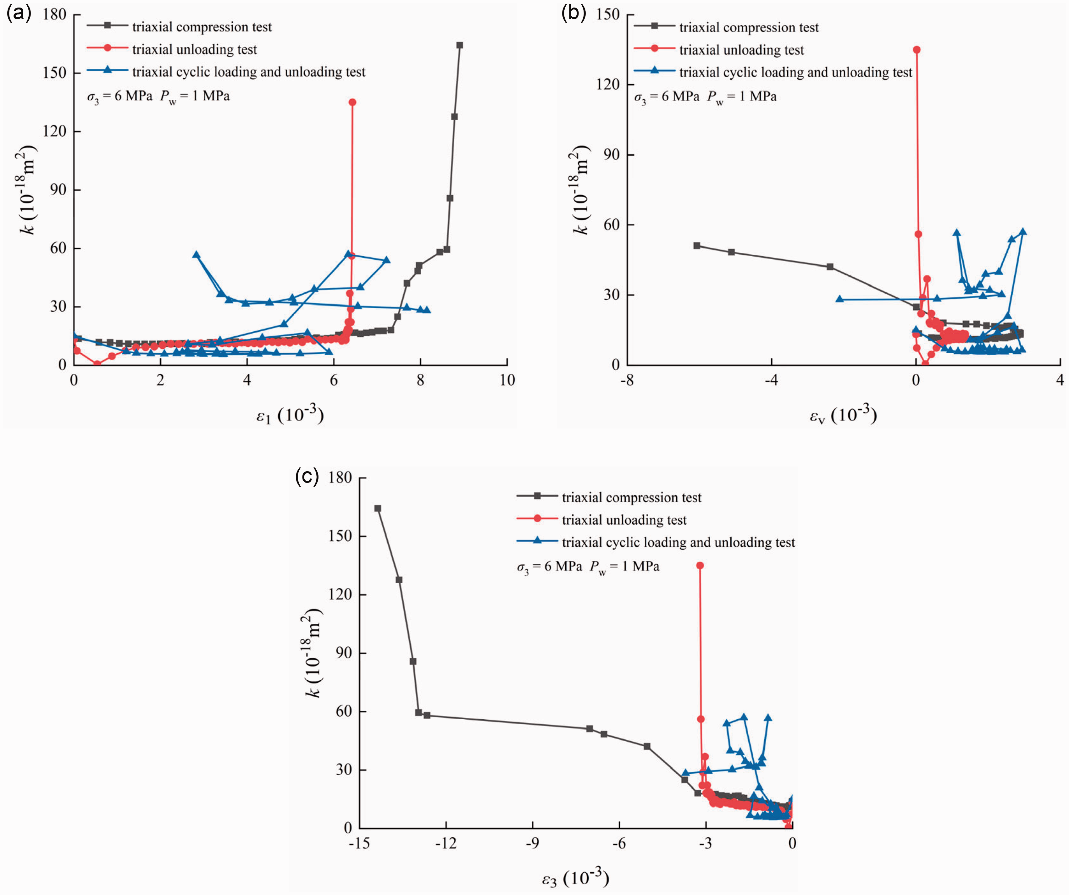
The relationship between permeability and triaxial strain of granite under three different testing paths (triaxial compression, triaxial unloading confining pressure, triaxial cyclic loading and unloading). (a) Permeability and axial strain; (b) permeability and volumetric strain and (c) permeability and lateral strain.
Figures 27(a) and (c) show that when permeability mutation occurs, the axial strain and lateral strain of triaxial compression are the largest, and the axial strain and lateral strain of cyclic loading and unloading are the smallest. The volume strain of the permeability sudden change during compression loading is the smallest, and the volume strain of the permeability sudden change during triaxial compression and cyclic loading and unloading is approximately the same. It can be seen from the comparison of Figures 5, 13 and 18 that when the rock is loaded under the same stress path, although the permeability of the rock will decrease with increasing effective confining pressure, the change trend of the curve is roughly the same.
Effect of σeff on failure mode of granite under triaxial compression
The initial stress state of the rock, the stress loading path, the test environment and other factors will all affect its fracture mode. Generally, in the triaxial test of rock, the failure modes of rock specimens are splitting failure, shear failure and coexistence and mixed failure. The failure situation of the triaxial compression test of granite is shown in Table 3. It can be seen from the table that the failure modes of gneiss are tensile splitting failure and shear failure, and the failure modes are related to σ3, Pw and σeff.
Failure mode of granite under different confining stresses and seepage pressures.
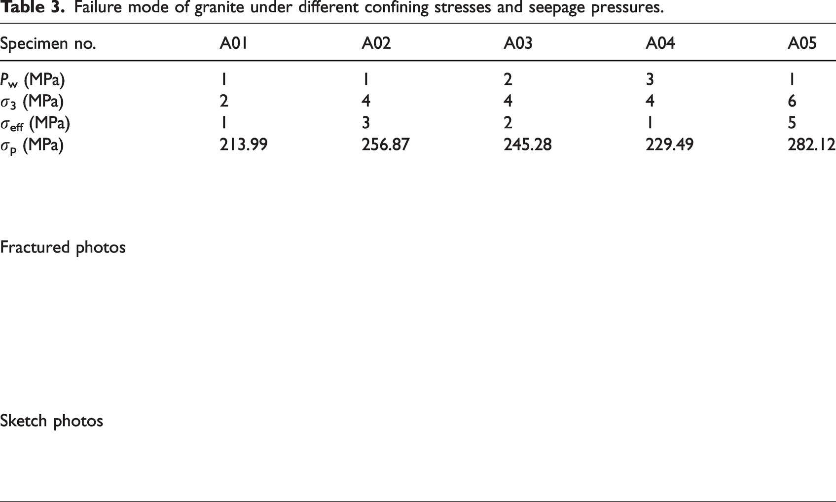
When under the stress conditions of the same seepage pressure (Pw = 1 MPa) and different confining pressures, the confining pressures of A01, A02 and A05 are 2 MPa, 4 MPa and 6 MPa, respectively, from the table. The main failure form of rock is tensile splitting failure. With the increase in confining pressure, the confining pressure on the rock is strengthened, the failure deformation is limited, and the rock transitions from tensile splitting failure to shear failure.
When under the stress conditions of the same confining pressure (σ3 = 4 MPa) and different seepage pressures, the seepage pressures of the A02, A03 and A04 specimens are 1 MPa, 2 MPa and 3 MPa, respectively. With the increase in seepage pressure, the unloading effect of seepage pressure on confining pressure is enhanced. With the increase in seepage pressure, the water wedge effect caused by seepage pressure increases the tensile stress at the tip of the internal crack of the rock, causing the expansion of internal microcracks, and the angle between the main fracture surface of the rock and the principal stress gradually decreases; that is, shear failure transitions to tension-splitting failure.
There is a more direct relationship between the rock failure mode and effective confining pressure. Comparing the fracture surfaces of the granite specimens after failure, when the effective confining pressure is low, the rock mainly presents tensile failure modes such as A01 and A04. With the increase in effective confining pressure, rock ductility is enhanced, and the failure mode is gradually transformed into shear failure. At the same time, each stress failure process has at least one main rupture surface, and when the effective confining pressure is low, there are more rupture surfaces, such as A04, and when the effective confining pressure is high, it presents X-shaped shear failure characteristics, such as A05.
Deformation parameter evolution of granite under triaxial cyclic loading and unloading
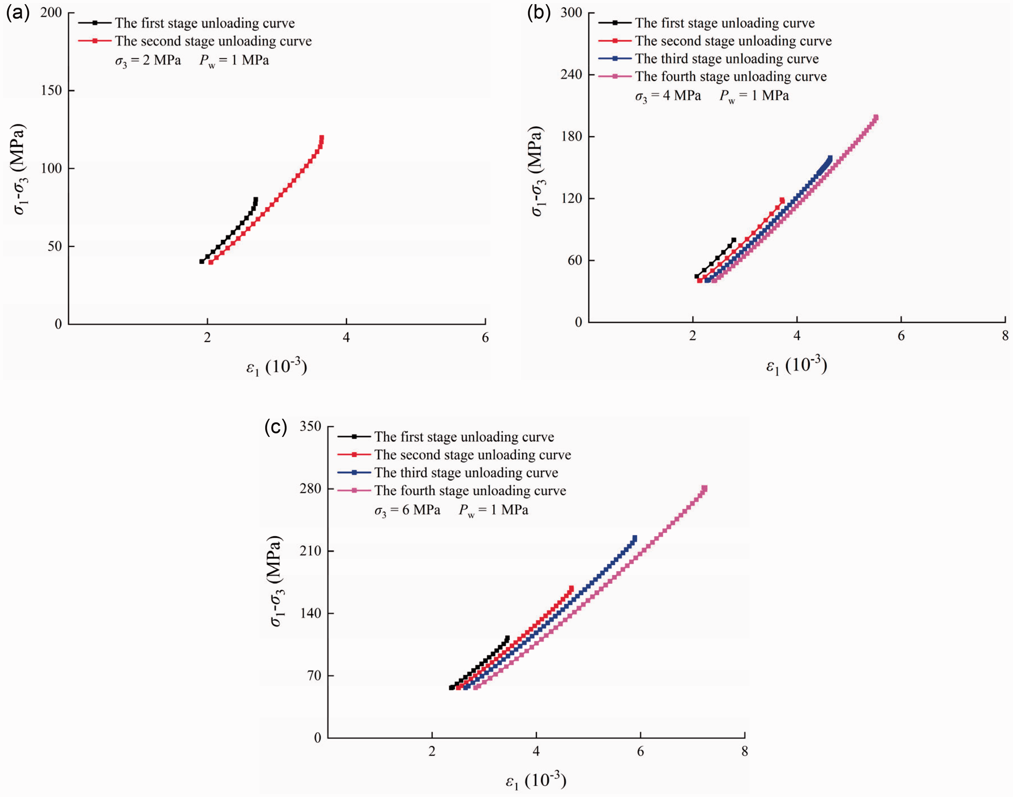
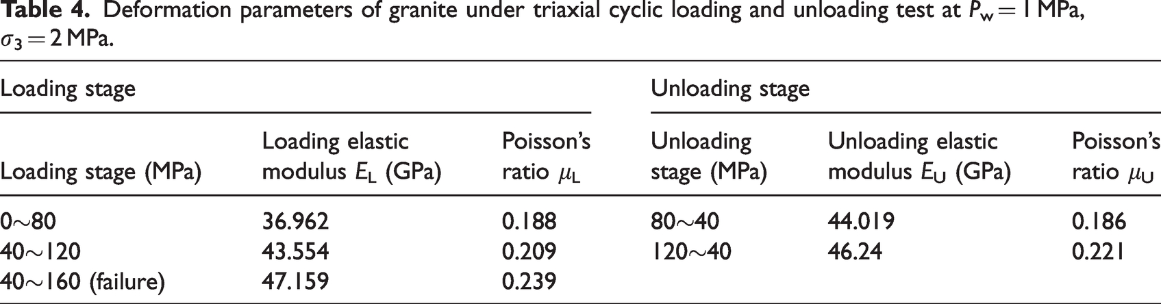
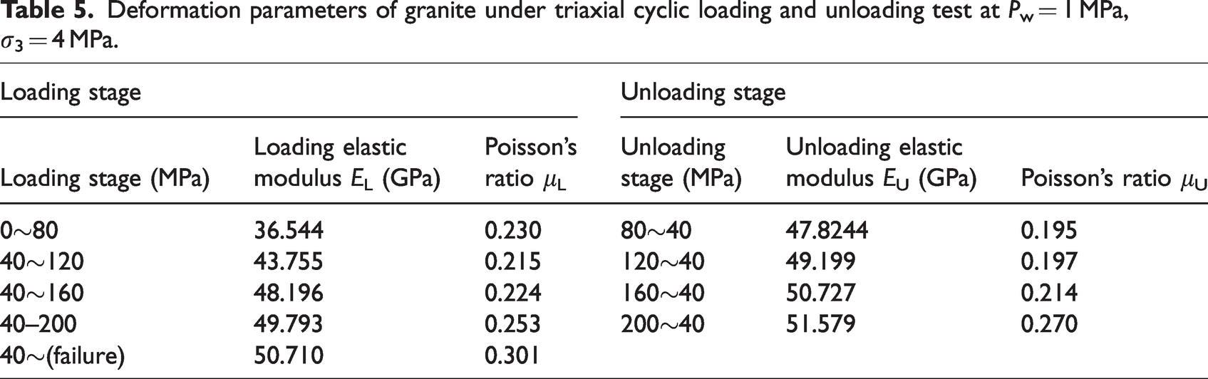
Figures 28 and 29 show the loading and unloading curves of the axial strain of granite, respectively. The cyclic loading and unloading test curves are quite different from the previous test results. Figures 28 and 29 indicate that the loading and unloading curves follow similar patterns across all stress levels and can be divided into straight line segments and curved segments at both ends. Additionally, Tables 4 to 6 present the deformation parameters of granite under triaxial cyclic loading and unloading test. Tables 4 to 6 show that the Poisson's ratio of granite continues to increase with increasing loading series, and the variation range is large.
Stress–strain curves of granite at loading stage under triaxial cyclic loading and unloading test. (a) σ3 = 2 MPa, Pw =1 MPa; (b) σ3 = 4 MPa, Pw = 1 MPa and (c) σ3 = 6 MPa, Pw = 1 MPa.
Stress–strain curves of granite at unloading stage under triaxial cyclic loading and unloading test. (a) σ3 = 2 MPa, Pw =1 MPa; (b) σ3 = 4 MPa, Pw = 1 MPa and (c) σ3 = 6 MPa, Pw = 1 MPa.
Deformation parameters of granite under triaxial cyclic loading and unloading test at Pw = 1 MPa, σ3 = 2 MPa.
Deformation parameters of granite under triaxial cyclic loading and unloading test at Pw = 1 MPa, σ3 = 4 MPa.
Deformation parameters of granite under triaxial cyclic loading and unloading test at Pw = 1 MPa, σ3 = 6 MPa.
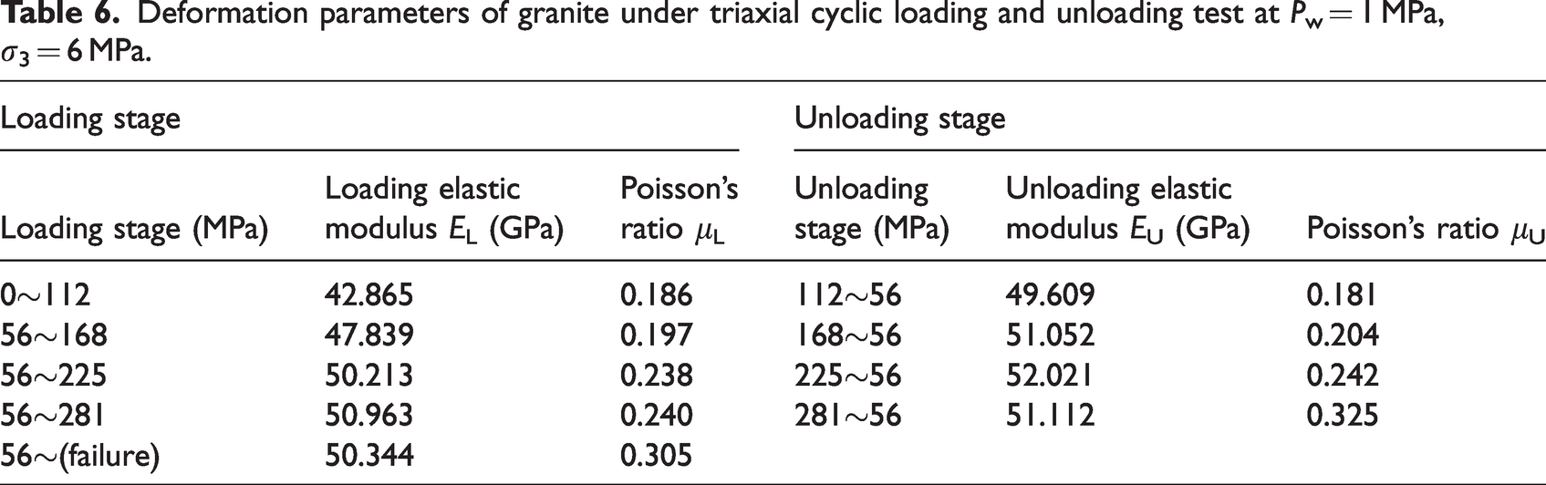
As shown in Figure 30, the elastic modulus of loading shows a trend of first increasing obviously and then decreasing slightly with increasing loading level; that is, the elastic modulus of the first loading stage increases obviously, and the subsequent loading stage gradually increases. trend, but little change, and when loaded to a certain value, the elastic modulus tends to decrease. The reason is that after the first cycle of loading and unloading, defects such as microcracks and pores in the granite are compacted, and initial plastic strain is generated in the compaction stage. After unloading, these compacted defects will not rebound and release. Therefore, after the first loading, the elastic modulus of the rock is strengthened; after the rock undergoes the strengthening effect of the first axial compression cycle loading and unloading, the microcracks and pores inside the rock are compacted. When cyclic loading and unloading continue, the rock skeleton is compressed, and the fractures are further compacted. However, because of the high stiffness of the rock skeleton, the compaction effect of microcracks is not obvious, so the deformation modulus only increases slightly. However, with the increase in the load level, before the rock enters the unstable fracture development stage, new cracks also begin to occur inside the rock, and the primary cracks are further closed. When the crack closure trend is greater than the degree of new crack generation, the elastic modulus continues to increase slowly. When crack initiation dominates, the elastic modulus appears to decay. When the load does not exceed the cyclic loading and unloading stress level required for the unstable growth stage of microcracks, the damage accumulation of the rock is very small, so the decreasing trend of the elastic modulus is relatively slow. The coefficient of variation of the elastic modulus of the reloading curve is very small after the first loading enhancement and before the elastic modulus decays.
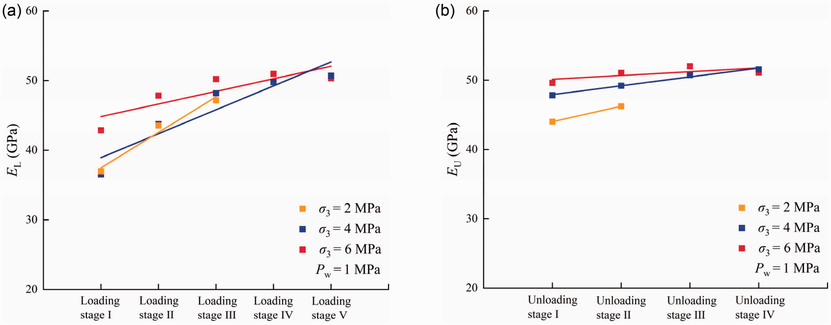
Comparison of elastic modulus of granite in each stage under different triaxial cyclic loading and unloading conditions. (a) Loading stage and (b) unloading stage.
Conclusion
In this paper, the effects of σ3 and Pw on permeability evolution and deformation characteristics were studied by triaxial compression tests, triaxial unloading confining pressure tests and triaxial cyclic loading and unloading tests. The strength and failure characteristics of granite under different stress paths and stress conditions were further analyzed. Based on the experimental result, the damage evolutions were analyzed under three different testing paths and the seepage-stress coupling statistical damage constitutive model was established, which can better simulate the seepage-stress coupling deformation behaviors of different paths, the main conclusion as follows:
Under triaxial compression and unloading confining pressure, the permeability of granite experiences a gradual decrease, then tends to be stable, and then changes abruptly with the increase of stress. When σ3 is low or Pw is high, the strain of granite permeability mutation is small. Under triaxial cyclic loading and unloading conditions, the permeability curve of rock can form multiple permeability hysteresis loops. In addition, the volume strain is closely related to the permeability, which can reflect the change of permeability more clearly than other strains. Therefore, the volume turning strain (volume turning stress) can be taken as an index of rock permeability change, providing reference for seepage stability analysis of rock engineering. The characteristics of rock deformation and permeability are significantly influenced by stress paths. The initial permeability of granite under various stress paths remains nearly the same. Nevertheless, the compaction effect of rock under triaxial cyclic loading and unloading is comparatively more pronounced, resulting in the lowest permeability being observed under this specific stress path. Additionally, cyclic loading and unloading induce greater internal damage to the rock compared to the other two loading methods, exhibiting significantly different patterns of permeability variation and an earlier occurrence of the permeability mutation point. Based on Drucker-Prager strength criterion, a new seepage-stress coupling statistical damage model is established. Compared with the experimental curves of rock under different stress paths, the simulation curves of the model established have a high consistency at all stages. The obtained results demonstrate that the proposed model (equation (24)) shows good simulation results the seepage stress coupling test results of red sandstone, sandstone, and altered rock. Although the stress paths are different, the fitting relationship between parameters R0 and n and σeff is similar and has a good correlation. The σeff has a direct influence on the failure mode of rock. When the σeff is low, the failure mode of granite is mainly tensile splitting. When the σeff is high, the failure mode of granite is mainly shear failure. In addition, the peak strength of rock under high σeff also increases correspondingly, and the rock permeability at the same failure stage is smaller than that under low effective confining pressure.
Highlights
A series of different stress path tests such as triaxial compression, triaxial unloading confining pressure and triaxial cyclic loading and unloading were carried out. The effects of different stress paths, stress levels and seepage pressures on rock deformation, strength, failure and permeability were investigated. The damage evolutions were analyzed under three different testing paths and a new seepage-stress coupling statistical damage model which can better simulate the compaction stage is proposed. Under different stress paths, the fitting relationship between parameters R0 and n and σeff is similar and has good correlation.
Footnotes
Declaration of conflicting interests
The authors declared no potential conflicts of interest with respect to the research, authorship, and/or publication of this article.
Funding
The authors disclosed receipt of the following financial support for the research, authorship, and/or publication of this article: The main financial support for this publication is the National Natural Science Foundation of China (Grant No. 52109119); the Guangxi Natural Science Foundation (Grant No. 2021GXNSFBA075030); the Guangxi Science and Technology Project (Grant No. Guike AD20325002); the Open Fund of Key Laboratory of Geological Hazards on Three Gorges Reservoir Area (China Three Gorges University), Ministry of Education (Grant No.2022KDZ11); the Open Research Fund of State Key Laboratory of Simulation and Regulation of Water Cycle in River Basin (China Institute of Water Resources and Hydropower Research) (Grant No. IWHR-SKL-202202); the Systematic Project of Guangxi Key Laboratory of Disaster Prevention and Engineering Safety (Grant No.2020ZDK007).