
Abstract
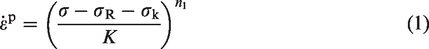
Forming limit curves (FLCs), which are constructed using the limit strains at localised necking, are the most widely used tools for the evaluation of the formability of sheet metals. Fracture forming limit curves (FFLCs) are more recently developed, complementary tools for formability evaluation which are instead constructed using the limit strains at fracture. Since the formability depends strongly on forming conditions such as strain state, temperature and strain rate, models for predicting FLCs and FFLCs are essential for the optimisation and further application of hot forming processes in which these forming conditions vary significantly with both position and time. However, no model has so far been developed to predict FFLCs either alone or in conjunction with FLCs for sheet metals such as boron steel under hot stamping conditions. In this study, a set of unified viscoplastic constitutive equations for the prediction of both FLCs and FFLCs based on continuum damage mechanics (CDM) has been formulated from a set of recently developed constitutive equations for dislocation-based hardening, in combination with two novel coupled variables characterising the accumulated damage leading to localised necking and fracture. The novel variables take into account the effects of strain state, temperature and strain rate on the formability of sheet metals. The material constants in the CDM-based constitutive equations have been calibrated using experimental data comprising true stress-true strain curves and limit strains of a 22MnB5 boron steel obtained at a range of temperatures and strain rates. Investigation of the effect of varying selected parameters in the coupled damage variables on the resulting computed FLCs and FFLCs has demonstrated the flexibility of the model in enabling curves of different shapes and numerical values to be constructed. This indicates the potential of the CDM-based constitutive model for application to other materials for warm or hot stamping processes.
Keywords
Introduction
Hot stamping of boron steels is commonly used for forming automotive panel components with complex shapes and ultra-high ultimate tensile strength (UTS) of up to 1500 MPa for a wide range of industrial applications (Karbasian and Tekkaya, 2010). For example, hot stamped steel components and assemblies were widespread in nearly all vehicle models which were to be launched onto the market in 2019 (Bachman, 2018). In a hot stamping process, boron steel is heated to above the austenitic temperature Ae3 (around 900 °C) to produce an austenitic microstructure and then transferred into water-cooled dies for simultaneous stamping and quenching (Li et al., 2016). It is well known that the formability of sheet metals varies with strain path, temperature and strain rate (Bruni et al., 2010; Khan and Baig, 2011), all of which significantly vary with both position and time in industrial hot forming processes (Gao et al., 2017; Karbasian and Tekkaya, 2010). However, it is not possible to determine the formability of materials under arbitrary sets of conditions such as those encountered in hot stamping (Min et al., 2010; Turetta et al., 2006) using existing experimental procedures. Instead, formability is evaluated under a limited number of discrete, ideal conditions such as uniaxial, plane-strain and equi-biaxial tensions at constant temperatures and strain rates, and the resulting values are connected to construct forming limit diagrams (FLDs) (Shao et al., 2016). Therefore, developing a constitutive model which enables the formability of the materials under arbitrary forming conditions to be predicted is essential for the optimisation and further applications of practical hot stamping processes.
FLDs are the most popular tools used to represent the formability of sheet metals (Goodwin, 1968; Keeler, 1965). An FLD is a plot of the limit strains at the onset of localised necking in principal strain space. Forming limit curves (FLCs) are constructed by connecting limit strains in strain states from uniaxial to equi-biaxial obtained at a given temperature and strain rate. Due to their high sensitivity to strain paths, the limit strains at localised necking are usually obtained through loading with linear strain paths (Hu et al., 2018; Kuroda and Tvergaard, 2000). The fracture forming limit diagram (FFLD) is an extension of the FLD (Atkins, 1996), in which fracture forming limit curves (FFLCs) are constructed by connecting the limit strains at fracture in different strain states for a given temperature and strain rate. According to the experimental data (Figure 3 in Section Determination of material constants from experimental data) on boron steel under hot stamping conditions reported by Zhang et al. (2022), there is a large difference between the limit strains at the onset of localised necking and those at fracture. From this experimental work, it has also been observed that with increasing deformation, necking progresses continuously, terminating at fracture. In some forming cases, however, it is very difficult to observe the onset of necking under hot stamping conditions. Therefore, in addition to FLCs, the use of FFLCs as complementary formability evaluation tools can improve the understanding of the extent of deformation before fracture in practical forming processes in ductile materials. The use of FFLCs to complement FLCs for the determination of formability has previously been reported in (Isik et al., 2014; Zahedi et al., 2019).
Considerable efforts have been devoted to the modelling of FLCs for metal forming applications (Bouktir et al., 2017; Brunet et al., 2004; Chan et al., 2005; Chow and Jie, 2009; Li et al., 2019; Thibaud et al., 2016). A brief review of the models for FLCs can be found in Zhang et al. (2018). Based on the theories adopted to describe failure mechanisms in the material, these models can be mainly divided into four categories: (i) models based on bifurcation theory, e.g. Hill’s model (Hill, 1952), Swift’s model (Swift, 1952), modified maximum force model (Hora et al., 2007, 2013), Stören and Rice’s (S-R) vertex theory (Stören and Rice, 1975), (ii) models based on geometrical imperfection theory, e.g. the Marciniak and Kuczyński (M-K) model (Marciniak and Kuczyński, 1967), modified M-K models (Hutchinson et al., 1978; Needleman and Triantafyllidis, 1978; Parmar et al., 1977), (iii) models based on continuum damage mechanics (CDM), e.g. plane-stress CDM-based models (Lin et al., 2014; Mohamed et al., 2015), and (iv) others, e.g. an empirical model proposed by the North American Deep Drawing Research Group (NADDRG) (Levy, 1996), and the Jones and Gillis (J-G) model (Jones and Gillis, 1984). Although most of the existing models for FLCs have been applied to cold forming processes, some have also been applied to high-temperature forming by taking into consideration the influence of temperature on deformation and failure in the material (Jie et al., 2011). For example, the S-R vertex theory was used to predict FLCs for boron steel (22MnB5) under hot stamping conditions by Min et al. (2010) and magnesium alloy at elevated temperatures by Min et al. (2013). The M-K model was adopted to predict FLCs at elevated temperatures for AA5083 by Zhang et al. (2009) and for AA3003 by Abedrabbo et al. (2006a, 2006b). By contrast, the plane-stress CDM-based model of Lin et al. (2014), in which a set of dislocation-based hardening constitutive equations and a damage variable was used, was developed purposely for predicting FLCs in sheet metals under hot stamping conditions and was successfully applied to the formability prediction for AA5754 in warm forming processes (Bai et al., 2016). A modification of this CDM-based model was adopted by Shao et al. (2017) for the prediction of FLCs in AA6082 under hot stamping conditions.
Many approaches have been developed for modelling of FFLCs, but few of them have been applied to hot forming processes (Shi et al., 2015). In the existing models for FFLCs, various ductile fracture criteria which are not coupled with other parameters have been commonly used to model fracture behaviour in the material (Bao and Wierzbicki, 2004; Cao et al., 2018; Han and Kim, 2003; Li et al., 2020; Liu and Fu, 2014; Lou and Huh, 2013; Park et al., 2017; Tang et al., 1999; Wierzbicki et al., 2005). Since strain state has a significant effect on damage evaluation (Foster et al., 2011; Kaye et al., 2016), based on the McClintock fracture criterion (McClintock, 1968), Atkins (1996) constructed analytically a fracture locus (i.e. an FFLC) consisting of a line with a slope equal to −1 in the coordinate system of major strain
Furthermore, no single model has been developed that is capable of predicting both FLCs and FFLCs for sheet metals under hot stamping conditions. This is partly due to the lack of available experimental data on FLCs and FFLCs for the calibration of material models. Recently, both FLCs and FFLCs for 22MnB5 boron steel under hot stamping conditions were determined for the first time using a biaxial test method developed by Zhang et al. (2022). This provides fundamental experimental data on FLCs and FFLCs for the calibration of the model developed in the present study.
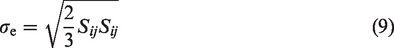
The aim of this study is to formulate a set of CDM-based unified viscoplastic constitutive equations for modelling both FLCs and FFLCs for boron steel for hot stamping applications. This model allows prediction of whether the material has passed the necking strain limit, and also estimation of how far the material is away from the fracture strain limit. For this purpose, two novel coupled damage variables are proposed to model the accumulated damage in the material leading to localised necking and fracture respectively. The model incorporates these new damage variables in combination with a set of constitutive equations for dislocation-based hardening. The material constants in the CDM-based constitutive equations are determined by curve fitting of the associated experimental data, i.e. true stress-true strain curves and limit strains for the boron steel under hot stamping conditions. Furthermore, the effects of varying selected parameters in the damage variables on the functional form and numerical values of both FLCs and FFLCs computed using the CDM-based equations are investigated and discussed.
CDM-Based unified viscoplastic constitutive equations for FLCs and FFLCs
This section presents a CDM-based unified viscoplastic constitutive model for FLCs and FFLCs. This model is formulated on the basis of the recently developed unified constitutive equations for dislocation-based hardening (Lin et al., 2014), coupled with two novel damage variables developed in the present study for modelling necking and fracture, respectively. Considering the relatively low thickness of the material used in hot stamping processes (e.g. 1.5 mm for the material in the present study), a plane-stress condition is assumed, i.e.
Dislocation-based unified constitutive equations for hardening
Dislocation-based unified constitutive equations for hardening were originally developed for the uniaxial stress case (Lin and Liu, 2003), and then extended to multiaxial stress states (Lin et al., 2014). These equations are introduced briefly in the subsections below to enable ease of understanding of the subsequent implementation and calibration of the CDM-based constitutive model developed in the present study. Specifically, the constitutive equations for the uniaxial stress state will be calibrated using true stress-true strain curves in Subsection Dislocation-based hardening constitutive equations (Uniaxial), and those for the multiaxial stress states will be calibrated using limit strains at the onsets of necking and of fracture in Subsection CDM-based unified viscoplastic constitutive equations (Multiaxial).
Uniaxial relations
Under hot stamping conditions, the flow stress
It is well known that the degree of isotropic hardening is directly related to the dislocation density. Based on this observation, an isotropic hardening equation was first developed as a function of average dislocation density by Sandström and Lagneborg (1975). In solving initial value problems, however, it is usually difficult to determine the initial value of the dislocation density which varies with material, chemical composition and processing route. In order to overcome this difficulty, a normalised dislocation density parameter

The dislocation density is a result of contributions from multiple mechanisms associated with high-temperature deformation. Equation (3) is an expression for dislocation density taking into account static and dynamic recovery (Garrett et al., 2005), in which the first term

Hooke’s law is used to describe the linear relationship between the flow stress and the elastic strain:

Multiaxial relations
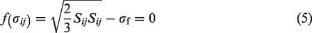
At hot stamping temperatures, 22MnB5 boron steel sheet exhibits only very weak anisotropy, such that isotropic behaviour can be assumed for simplicity (Merklein and Lechler, 2009; Turetta et al., 2007). Therefore, the Von Mises yield criterion is used to describe the yield surface

Recalling the associated flow rule that describes the relationship between the yield surface

The multiaxial power-law viscoplastic equations are obtained by consideration of a dissipation potential function (Lin et al., 2014). With the initial yield stress
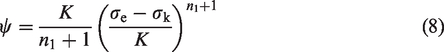
Based on the associated flow rule (equation (7)), the strain rate equation then becomes:

By introducing the isotropic hardening
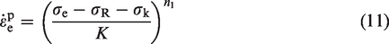
Note that equation (11) is applicable only when
The isotropic hardening under multiaxial stress conditions takes the same form as equation (2). The normalised dislocation density
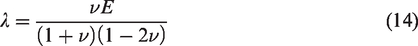
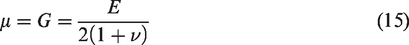
The generalised Hooke’s law, which defines the general linear relation among all the components of the stress and strain tensors, is given by:


CDM-Based damage variables
Lin et al. (2014) were the first to develop a CDM-based constitutive model to predict FLCs for sheet metals under hot stamping conditions under the assumption of plane-stress conditions, coupled with a damage variable to characterise the extent of necking. Since an FLC is constructed using limit strains, Mohamed et al. (2015) modified this damage variable, replacing the stress components with strain components to model the effect of the stress or strain state on the damage evolution. The modified damage variable in multiaxial form is expressed as (Mohamed et al., 2015):
This modified damage variable
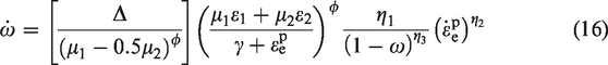
Based on the above-mentioned studies, in the present work, two novel coupled damage variables
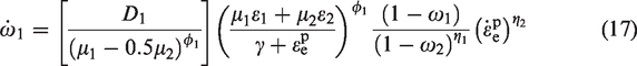

Similarly to the damage variable of equation (16), the first two factors of equations (17) and (18) (square and round brackets) describe the effects of the strain state on the damage evolution in the material, with the coefficients
By introducing the two novel damage variables

The damage variable
CDM-based unified viscoplastic constitutive equations
In summary, a set of CDM-based unified viscoplastic constitutive equations has been developed for the modelling of both FLCs and FFLCs for sheet metals under hot stamping conditions, which is written as:
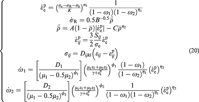
In equation (20), the parameters


Model implementation and discussion
Determination of material constants from experimental data
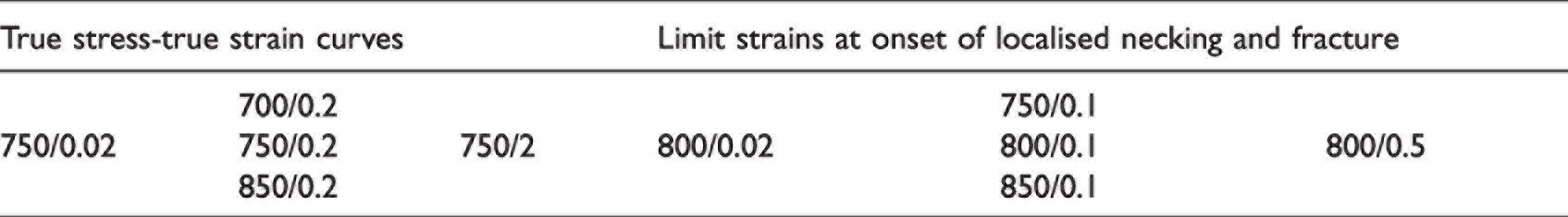
Experimental data on 1.5 mm thick 22MnB5 boron steel sheet at hot stamping temperatures reported by some of the present authors are used for the determination of the material constants arising in equations (20) to (22). These data comprise true stress-true strain curves (Zhang et al., 2020), and limit strains at the onset of localised necking (i.e. FLCs) and at fracture (i.e. FFLCs) (Zhang et al., 2022) obtained under the conditions given in Table 1. These true stress-true strain curves of boron steel were obtained by carrying out uniaxial tensile tests under hot stamping conditions using a Gleeble thermal-mechanical simulator, together with the digital image correlation (DIC) technique for full-field strain measurement. To obtain experimental data for the construction of FLCs and FFLCs, cruciform specimens were deformed in different strain states and full-field strains within the gauge area were measured using the DIC technique, followed by the determination of the limit strain values using a spatio-temporal method originally developed by Zhang et al. (2021). The calibration process is divided into two steps. The first step is to determine the material constants within the dislocation-based hardening constitutive equations (equations (1) to (4)) using the true stress-true strain curves for the material. The damage variables can be neglected in this step since their values will be vanishingly small and have little influence on the viscoplastic deformation of the material in the initial stages of deformation. The second step is to determine the material constants in the equations for the two damage variables (equations (17) and (18)) using the experimentally determined limit strains at the onsets of localised necking and of fracture. The detailed procedures of the calibration are given in the following sections.
Test conditions, i.e. temperature (°C)/strain rate (s−1) of the experimental true stress-true strain curves and limit strains for 22MnB5 boron steel.
Dislocation-based hardening constitutive equations (uniaxial)
In order to calibrate the material constants in the dislocation-based hardening constitutive equations, equations (1) to (4) were solved using a numerical integration method combined with the explicit Euler method. There are a relatively large number of material constants (14 in total), which causes difficulties in the curve fitting. Many studies have been carried out to develop mathematical fitting methods to overcome the difficulties (Abushawashi et al., 2013; Cao and Lin, 2008). In the present study, an optimisation method based on the trust-region-reflective least square algorithm, implemented by means of the Lsqnonlin solver in MATLAB (MathWorks, USA), was used for the curve fitting.
In the numerical computations, initial values were given to each of the material constants and upper and lower boundaries set, all according to experience. The time increment
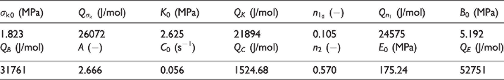
Material constants determined in the uniaxial dislocation-based unified hardening constitutive equations.
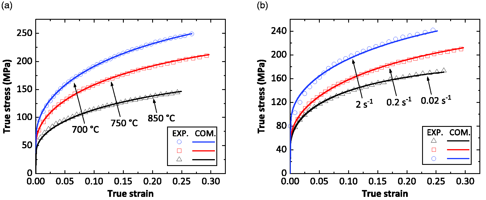
Comparison of the computed (COM.: solid lines) and experimental (EXP.: symbols) true stress-true strain curves of the boron steel at (a) 0.2 s−1 with temperatures from 700 to 850 °C and (b) 750 °C with strain rates from 0.02 to 2 s−1.
CDM-Based unified viscoplastic constitutive equations (multiaxial)
In the second step, the CDM-based constitutive equations summarised in equation (20) were also numerically solved using the explicit Euler method. Figure 2 shows the associated flow chart for the numerical computations. At the start of each computation (j = 1) under conditions of constant temperature T and effective strain rate 
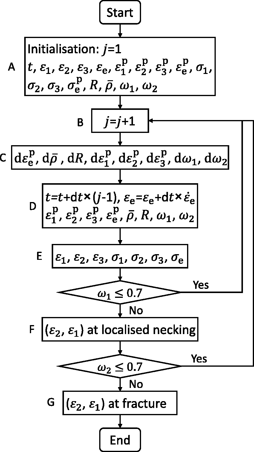
Flow chart for numerical integration of the constitutive equations.
Under proportional straining conditions, the strain ratio 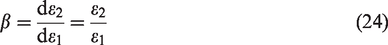
Furthermore, the effective strain 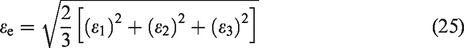
The principal strain components were computed by solving equations (23) to (25) using the Newton-Raphson method, and the principal stress components were then obtained according to the generalised Hooke’s law (box E). The above computations were repeated (j = j + 1) until the damage variable
Due to the current limitations of the biaxial test rig, which is able to produce three distinct displacement ratios only, only a few experimental limit strain data points are available for constructing FLCs and FFLCs (Zhang et al., 2022). Therefore, the curve fitting was performed by trial and error, in combination with a thorough understanding of the physical meaning of each variable and associated material constants in the equations. Specifically, the following substeps were performed:
Substep 1: According to the form of equations (17) and (18), in the uniaxial stress state ( Substep 2: The values of the temperature-dependent parameters Substep 3: The material constants in the temperature-dependent parameters (i.e.
In the above numerical computations of FLCs and FFLCs, the time increment
Material constants determined in the CDM-based unified viscoplastic constitutive equations.
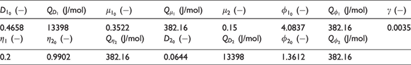
Figure 3 shows a comparison of the FLCs (solid lines) and FFLCs (dashed lines) computed using the material constant values given in Tables 2 and 3, with the associated experimental data (symbols) for the limit strains at the different temperatures (i.e. 750, 800 and 850 °C, Figure 3(a)) and strain rates (i.e. 0.02, 0.1 and 0.5 s−1, Figure 3(b)). Good agreement can be observed between the computed and experimental results.
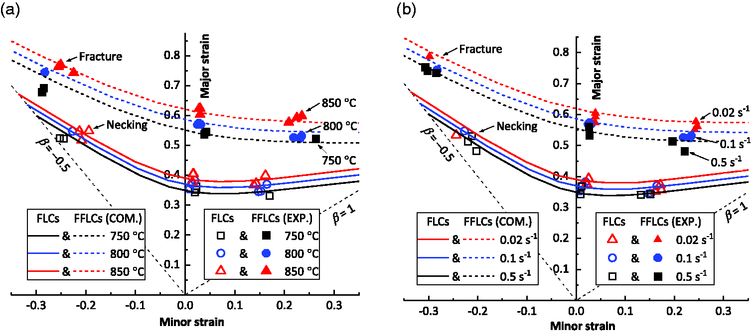
Comparison of the computed (COM.) data of FLCs (solid lines) and FFLCs (dashed lines) using the CDM-based constitutive equations and the associated experimental (EXP.) data (symbols) of the limit strains of the boron steel at (a) 0.1 s−1 and different temperatures from 750 to 850 °C and (b) 800 °C and different strain rates from 0.02 to 0.5 s−1.
Figure 4 shows the evolution of the damage variables
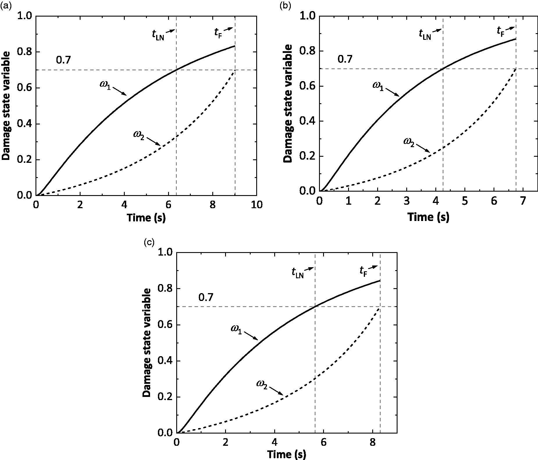
Evolution of the damage variables
Effects of novel damage variables on computed FLCs and FFLCs
This subsection aims to show the capability of the novel coupled damage variables to model FLCs and FFLCs of various shapes and numerical values. For this purpose, the effects of varying intentionally the values of selected parameters, i.e.
Values chosen for the parameters in the damage variables.

Parameters μ 1 and μ 2
Figure 5 shows the FLCs and FFLCs computed by varying the parameters
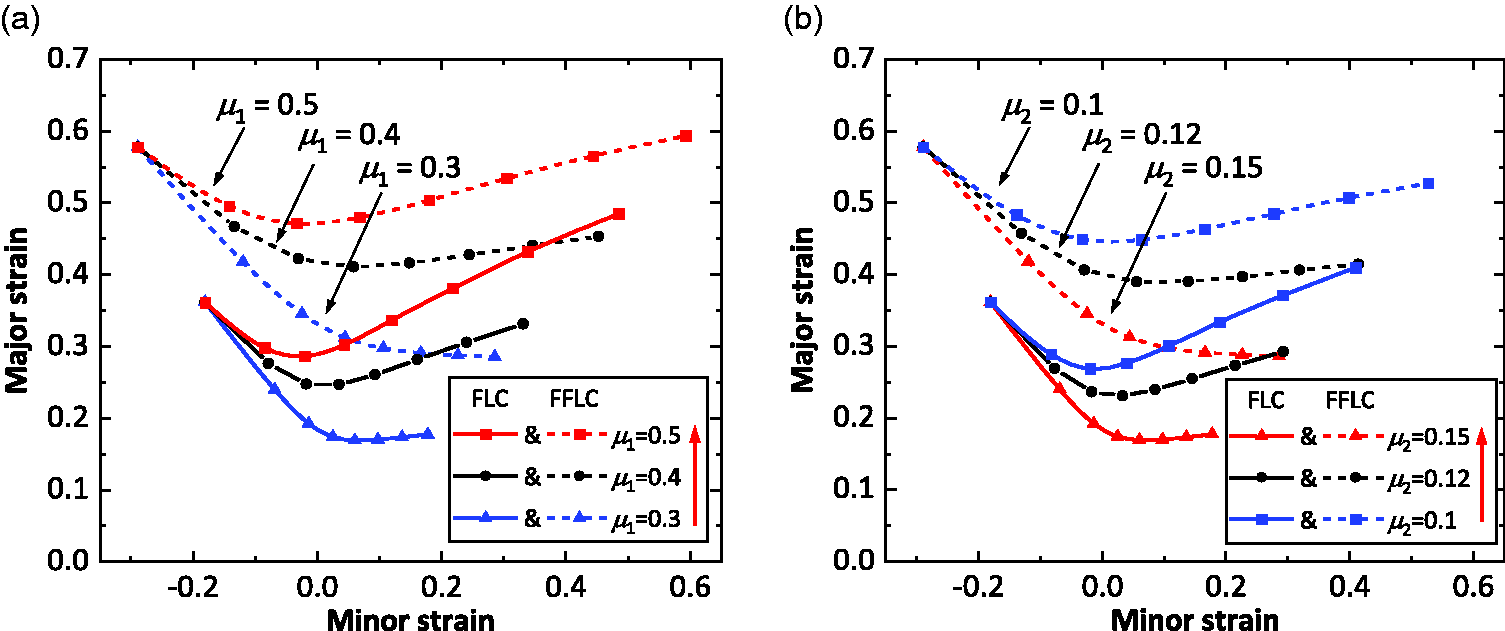
FLCs (solid lines) and FFLCs (dashed lines) computed using the CDM-based unified viscoplastic constitutive equations showing the effect of varying the parameters (a)
Parameters ϕ 1 and ϕ 2
Figure 6(a) presents the FLCs and FFLCs computed with
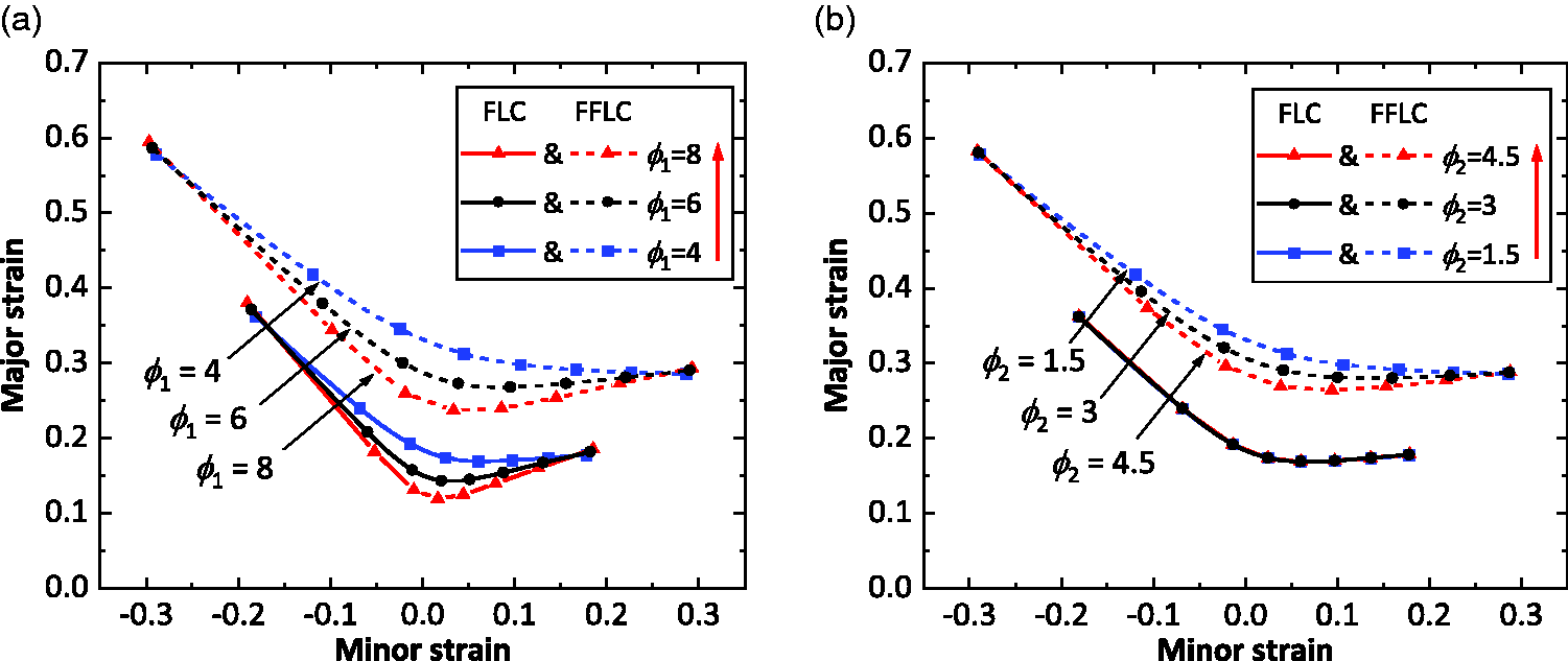
FLCs (solid lines) and FFLCs (dashed lines) computed using the CDM-based unified viscoplastic constitutive equations showing the effects of varying the parameters (a)
Parameters
and
Figure 7 shows the FLCs and FFLCs computed using different values of the parameters
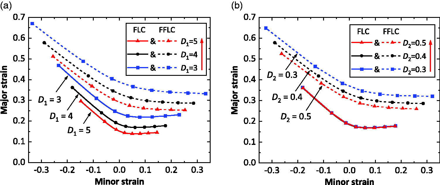
FLCs (solid lines) and FFLCs (dashed lines) computed using the CDM-based unified viscoplastic constitutive equations showing the effects of varying the parameters (a)
Discussion
The CDM-based unified constitutive equations are capable of modelling the limit strains at the onset of localised necking and at fracture for boron steel for hot stamping applications (Figure 3). According to Figures 5 to 7, the parameters (i.e.
Since there are a relatively large number of material constants in the CDM-based constitutive equations, the determination of these material constants is complex and difficult. According to Figure 1, the optimisation method based on the trust-region-reflective least square algorithm enables the material constants in the dislocation-based hardening constitutive equations (uniaxial) to be determined such that experimental stress-strain curves are reproduced accurately. However, one of the difficulties of using this method is the need to define suitable initial values and lower and upper bounds for each of the material constants. Furthermore, the material constants in the CDM-based damage variables were successfully determined by trial and error (Figure 3). However, the determination of material constants requires a deep understanding of the physical meaning of each of the variables and the associated material constants. Therefore, it is necessary to develop a simpler but still effective method for determining the material constants in the CDM-based constitutive equations, especially for industrial applications.
Conclusions
A set of CDM-based unified viscoplastic constitutive equations has been developed, for the first time, to model both FLCs and FFLCs for boron steel (22MnB5) sheet for hot stamping applications. These comprise a set of dislocation-based unified constitutive equations for hardening, and two novel coupled damage variables
The two damage variables which are dependent on strain rate and temperature take into account the influence of the strain state on formability, thereby providing sufficient flexibility to precisely reproduce the various shapes and numerical values of experimental FLCs and FFLCs. This indicates that the CDM-based unified viscoplastic constitutive model has great potential for application to other materials for modelling the formability under warm or hot stamping conditions.
The material constants in the CDM-based constitutive equations have been calibrated from the curve fitting of associated experimental data from true stress-true strain curves and from FLCs and FFLCs obtained at different temperatures and strain rates. However, the calibration requires a thorough understanding of the equations and considerable practical experience. For industrial applications, a simpler but effective method of determining the material constants is necessary.
Footnotes
Declaration of conflicting interests
The author(s) declared no potential conflicts of interest with respect to the research, authorship, and/or publication of this article.
Funding
The author(s) disclosed receipt of the following financial support for the research, authorship, and/or publication of this article: This work was supported by the Engineering and Physical Sciences Research Council (EPSRC) [grant number EP/R001715/1] on “Lightform: Embedding Materials Engineering in Manufacturing with Light Alloys”; and the Chinese Scholarship Council (CSC) Imperial Scholarship [grant number 201700260069].