
Abstract
The aim of this study involved evaluating and predicting forming limit curves of boron steel 22MnB5 sheet at elevated temperatures. A finite-element method simulation was adopted based on ductile fracture criteria and simple experiments at elevated temperatures. First, tensile experimental data and ductile fracture criterions of Johnson–Cook and ductile void growth models were input to ABAQUS/Explicit software to predict and compare the same with fracture occurrence in experiments performed via Hecker’s punch stretching tests at room temperature. Subsequently, punch stretching test data at room temperature were added to correct the fracture strain locus in the space of the stress triaxiality and the equivalent strain following the ductile void growth model. After confirming the accuracy of the forming limit curve prediction at room temperature, fracture strain loci at high temperatures using ductile void growth model were determined based on the average ratio between the fracture equivalent plastic strains at room temperature as well as higher temperatures. Finally, Hecker’s punch stretching tests were numerically simulated to predict forming limit curve(s) of boron steel 22MnB5 sheet at high temperatures.
Keywords
Introduction
In recent years, lower-weight high-strength steels are increasingly used in the automotive industry as they ensure the advanced safety of passengers while decreasing fuel consumption demands, and this is extremely important. The use of high-strength steel leads to a few disadvantages such as the reduction in formability due to their increased stress/poor strain and pronounced spring back. In order to successfully deal with these difficulties, hot press forming (HPF), that is, an advanced sheet metal forming method is upgraded to improve press formability via forming at an extremely high temperature and increasing high strength in part via rapidly cooling the inside dies. For continuous developments on the new HPF area, an accurate prediction of the formability in the quenchable high-strength steel is highly required in the automotive industry. Several studies illustrated the thermal and mechanical characteristics of a boron steel for a coupled thermo-mechanical analysis. Merklein and Lechler 1 verified the thermo-mechanical behaviors and formability of boron steel at various temperatures and concluded that the effects of temperature significantly influence the formability of the boron-manganese steel 22MnB5 and that the material exhibits better formability at higher temperature. Currently, finite element (FE) simulation is an indispensable tool to research, evaluate, and discern physical phenomenon modeled by various theoretical and experimental equations, and thus, several studies focused on a coupled thermo-mechanical simulation on high-temperature press forming.2–8 In order to improve the fitting of experimental data with numerical data, Hochholdinger et al. 9 upgraded the new FE simulation model via modifying Hockett–Sherby equation and determining Zener–Hollomon parameters. In order to investigate the effect of elevated temperatures on the spring back and formability of high tensile strength, Mori et al. 10 performed hat-shaped bending. Son and Kim 11 presented coupled thermo-mechanical methodology to analyze the formability of a hot press–formed part.
In order to investigate press formability of sheet metal forming at room temperature, Keeler and Backofen 12 and Hecker 13 proposed forming limit diagrams (FLDs), which are proven as an effective tool to determine defects that occur while performing the sheet metal forming process. The FLD corresponds to a diagram in the space of principal strains (major strain (ε1) and minor strain (ε2)), and this can be obtained from circle or square grid marks on the surface layer of various specimens during a sheet metal forming test until the fracture appears.14,15 At present, the forming limit curve (FLC) is typically used to assist in determining the optimal forming parameters of automotive parts. The FLD concept is mainly introduced to avoid the material waste and to also reduce the time and cost involved in the procedure of making prototypes.16–18 However, the circle grid marks disappear after forming processing when the material is exposed to high temperatures (Figure 1). This implies that it is impossible to measure the deformed principal strains. In order to obtain the FLD at elevated temperatures, Cui et al. 19 applied the equation of Abspoel et al. 20 based on special points from various tests including uniaxial tension, plane strain, and biaxial stretching. Other studies developed damage models, such as continuum damage mechanics (CDM), modified Gurson–Tvergaard–Needleman (GTN) model, and other models, to predict thermal FLD based on identified input parameters and then compared the same with those in corresponding experiments.21–26
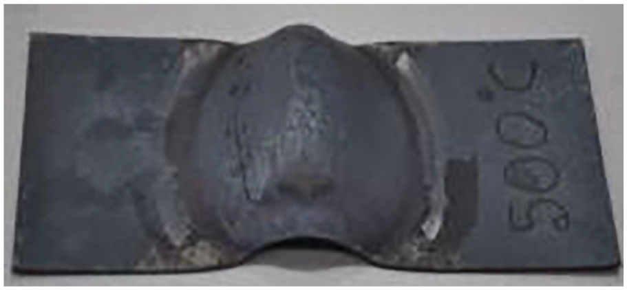
Deformed shape of the boron steel 22MnB5 sheet at 500°C.
This study focuses on the FLCs prediction at high temperatures using a finite-element model (FEM) simulation tool coupled with ductile fracture criterions to predict the failure at HPF of a boron steel 22MnB5 sheet. As mentioned above, FLCs are represented in the major strain (ε1) and minor strain (ε2) space, and Lee
27
proved that the curves in the major and minor strain space can be transformed into the space of the fracture equivalent plastic strains
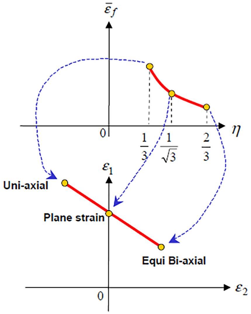
Schematic of the transformation from
Material, ductile fracture models, and experiments
Material
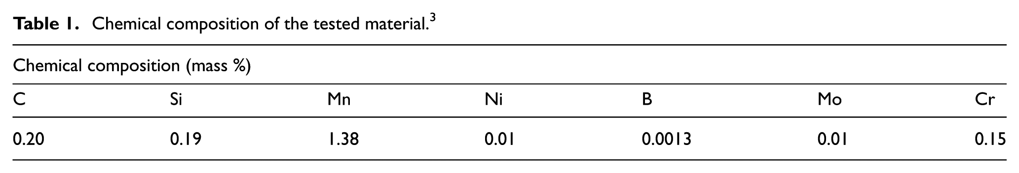
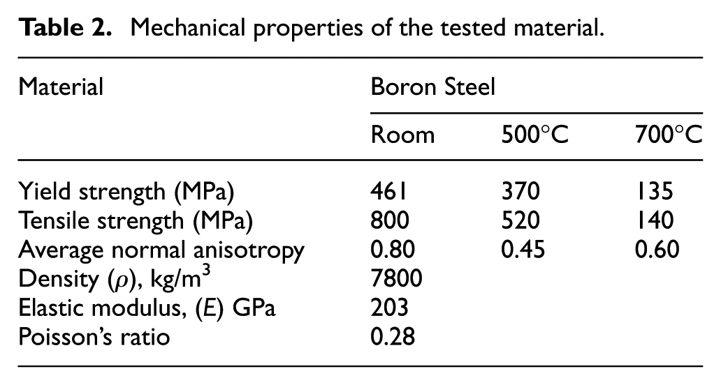
The uniaxial tensile specimens for boron (22MnB5) sheet metal test of 0.5-mm thickness were tested at room temperatures corresponding to 500°C and 700°C. Specifically, the test specimens were selected along the rolling direction of the metal sheet. Table 1 shows the chemical composition of the material sheet. The tensile test was performed at a nominal speed of 5 mm/min and a capacity corresponding to 25 kN. Figure 3 shows the flow stress curves of boron (22MnB5) metal sheet, and the mechanical properties of the boron materials are listed in Table 2, wherein planar anisotropic can be neglected, while normal anisotropic should be used as indicated by Merklein et al. 28 and Turetta et al. 29
Chemical composition of the tested material. 3
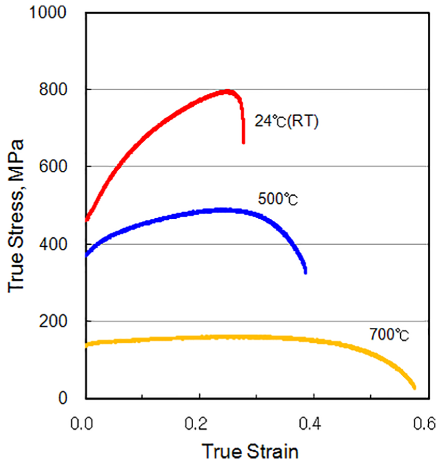
Stress–strain curves based on measured values. 3
Mechanical properties of the tested material.
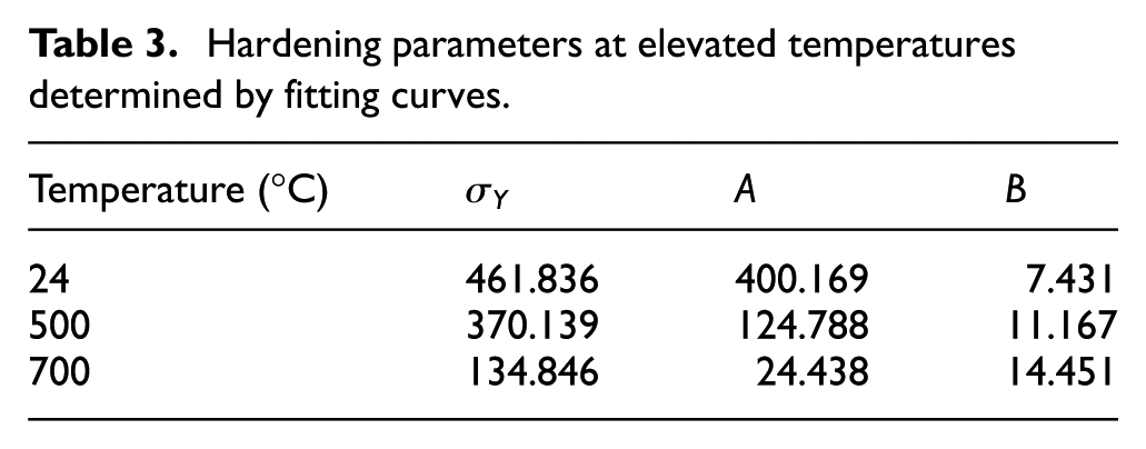
In order to fit the test data with the flow stress curves of Voce’s 30 hardening law, equation (1) was implemented using a (lsqcurvefit) command in MATLAB software to specify material parameters at various temperatures (Table 3) based on the mean values of stress–strain data to peak stress values as shown in Figure 4. The expression is as follows
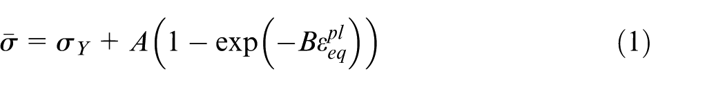
where A and B denote the plastic coefficients, and
Hardening parameters at elevated temperatures determined by fitting curves.
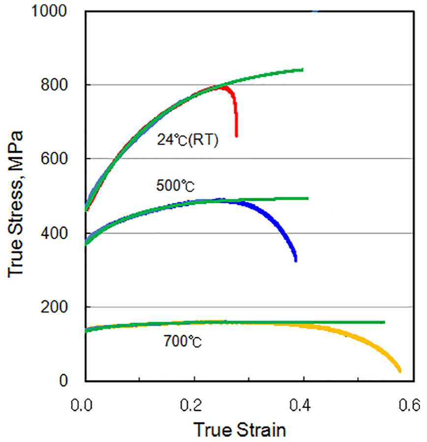
Comparison of fitting curves with experimental data at room and elevated temperatures.
Ductile fracture criterion
Several studies proposed various criteria for ductile fractures.31–35 In this study, we employ J-C 34 and ductile void growth 35 fracture models, wherein fractures are postulated such that the equivalent fracture strain is a monotonic function of the stress triaxiality as shown in equations (2) and (3) for the J-C and ductile void growth models, respectively

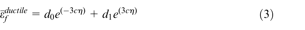
where the stress triaxiality parameter
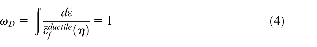
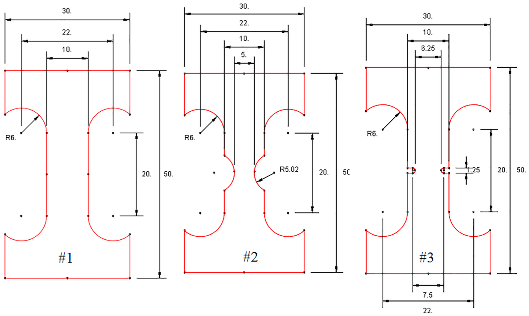
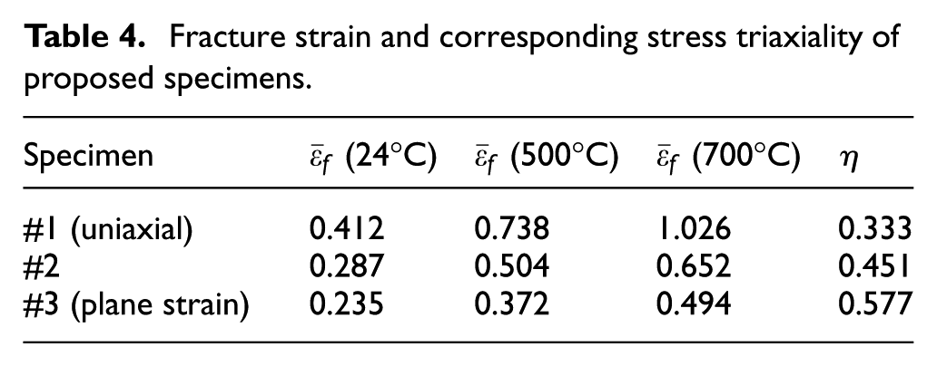
The metal steel sheet constants (i.e. C1, C2, C3, c, d0, and d1) in equations (2) and (3) are determined by performing various destructive tests based on specifying the types of stress triaxiality. Specifically, we proposed new tensile specimens at various stress triaxiality conditions based on the diffuse necking of dog-bone specimens36,37 as shown in Figure 5. In order to verify the stress triaxiality of proposed specimens, the FEM simulation tool was adopted to represent the evolutions of deformed shape and stress triaxiality for each specimen in Figures 6(a) and (b), respectively, and the average stress triaxialities are then introduced. In the experiments, jig and heating equipment is designed for proposed specimens as shown in Figure 7(a) and (b). The fracture strain and corresponding stress triaxiality at room and elevated temperatures for proposed specimens are also listed in Table 4.
Tensile specimens at various stress triaxiality conditions.
(a) Deformed shapes and (b) evolution of stress triaxiality for tensile tests.
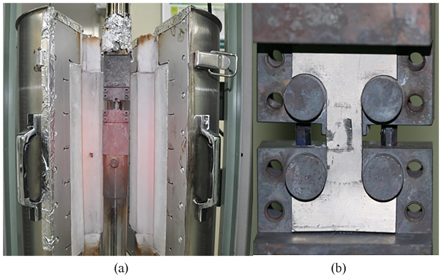
(a) Generation of heat and (b) jig equipment for the proposed specimens.
Fracture strain and corresponding stress triaxiality of proposed specimens.
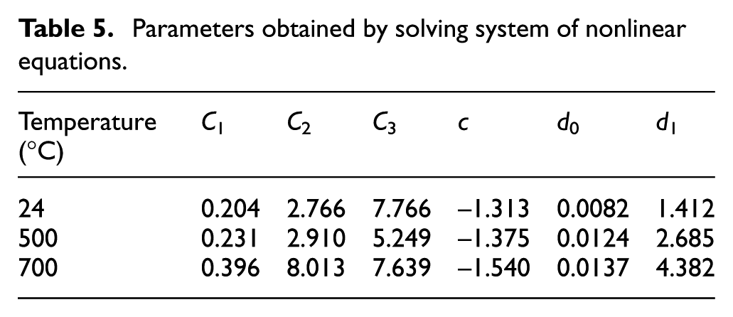
We substitute the data at room and high temperatures from Table 4 into equations (2) and (3) and use fsolve command in MATLAB to solve a system of nonlinear algebraic equations to obtain C1, C2, C3, c, d0, and d1 at room and high temperatures as shown in Table 5. The predicted fracture strain curves at elevated temperatures following J-C and ductile void growth models are illustrated in Figure 8. Evidently, the curves passed through the coordinates of test points. However, fracture strain curves of J-C model tend to decrease while the evolutions of ductile void growth model tend to increase after passing the last testing point. This corresponds to an important viewpoint for the selection of a fracture model to simulate and predict FLCs of boron-manganese steel 22MnB5 sheet at room and elevated temperatures.
Parameters obtained by solving system of nonlinear equations.
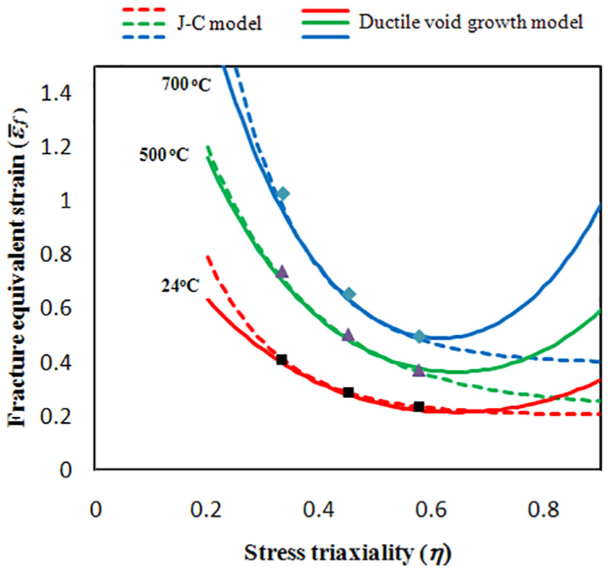
Comparison of the prediction of fracture models with experimental points.
Punch stretching tests at room temperature
In order to determine the FLC at room temperature, Hecker’s punch stretching tests 13 were performed for various specimens as shown in Figure 9. Specifically, the specimens were composed of sheet metal and required a large number of loads to form initial shapes via a hemispherical tool with a radius of 50 mm. Before a specimen was subjected to the stretching test, the markers of 2.54-mm circle grids were etched on the surface layer of all the specimens. The elastic pad, lubrication oil, and graphite foil were used to reduce the friction and to move the diffuse necking of specimens to the top of the hemispherical punch to increase the accuracy of deformed grid measurement. In order to ensure that the metal sheet is not drawn-in, the specimen was then set and tightly clamped using a holder bead, and the tool stroke was decreased at a speed of 10 mm/min. The tool stroke stops if the loads drop by approximately 1%–10%. Figure 10 shows the fracture that is tested after experimental processing. With respect to FLCs estimation, it is desirable to stop the test at incipient necking. The measurement of major/minor strains was performed based on the deformed circle grid on the surface layer of the sheet. In order to identify the necking and fracture near the deformed cycles, a high-quality digital camera was utilized to capture the image. Subsequently, in-house software was used to define the major/minor strain from the deformed circles. The FLC curves are plotted by fitting the data of failure relative to safety points and plotted on the major/minor strains axes as shown in Figure 11.
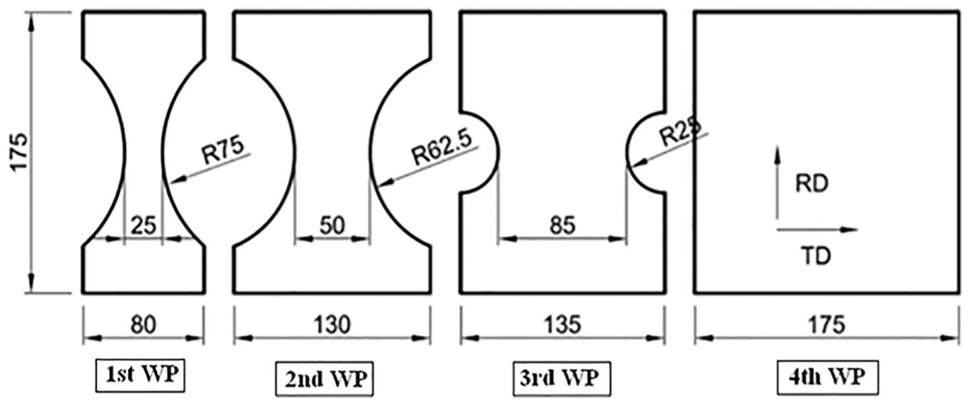
Shapes and dimensions of the FLD test specimens.
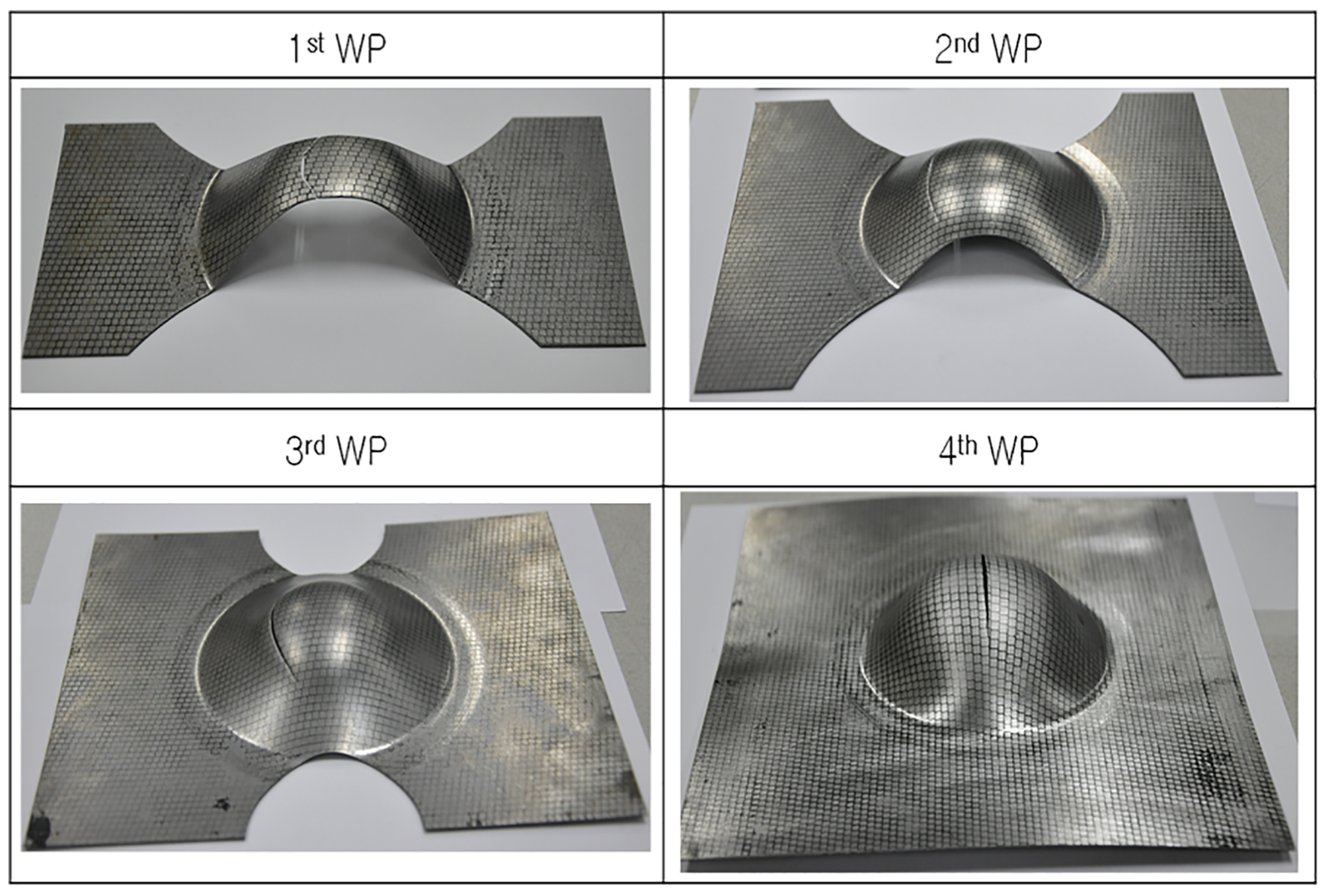
Fractured specimens in FLD tests at room temperature.
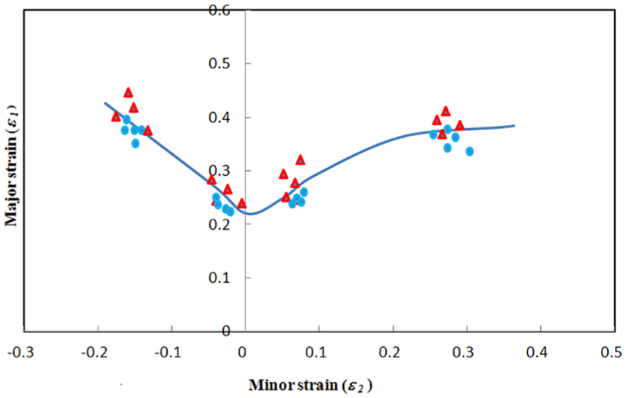
Forming limit curve at room temperature.
FE simulations
In this study, we use a commercial software ABAQUS (6.12) 38 to analyze the deformation of Hecker’s punch stretching tests. The software aids in simulating processes including metal machining, forming, and welding of elastic/plastic and rigid/plastic. This reduces the time and cost involved in designing and manufacturing punch/die of products.
The FEM software predicts several characteristics of the forming process such as fractures, wrinkling, and stress/strain distribution. Based on the simulation results, various parameters can be modified to verify their effect on the output data.39–42
Figure 12 shows the FE model for Hecker’s punch stretching tests of boron steel (22MnB5) sheets. Specifically, reduced-integration four-node linear shell elements (S4R) are utilized for the blank. The die/tool and clamping parts are assigned as the rigid body. The size of the element for all parts approximately corresponded to 1 × 1 mm (length × width). The mesh density is sufficiently fine to ensure result convergence. The mesh size is also refined by comparing initial simulations and corresponding experiments.
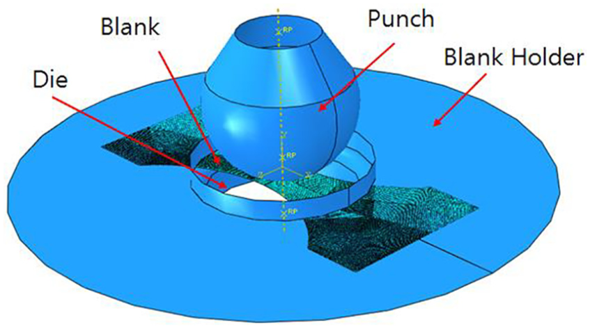
Finite-element model for forming simulation.
We fix the die by using the ENCASTRE condition. The tool and clamming part are permitted to run in the vertical direction. The blank specimen is held by the concentration force acting on the clamping part. The Coulomb friction law is used in the friction condition. The friction coefficient between the tool/blank, blank/die, and blank/clamming part is assumed to correspond to a dynamic friction of 0.1 with a graphite foil.43,44
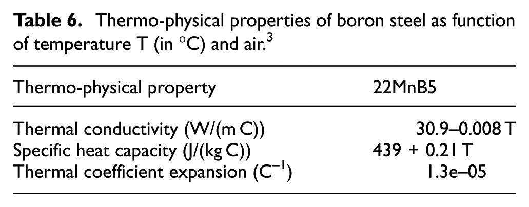
In order to investigate the effect of cooling temperatures, the heat transfer during punch and die quenching process is adopted via coupled thermo-mechanical computational modeling. At the beginning of the stretching process, desired temperatures are assigned to the blank specimen, die, and lamming part. During the stretching tests, heat transfer occurs from the surface of the specimen into the tool, die, and clamming parts. In the FEM simulation of the quenching process, thermal and material properties as the functions of temperatures of the boron steel (22MnB5) sheets are adopted as shown in Table 6.
Thermo-physical properties of boron steel as function of temperature T (in °C) and air. 3
Results and discussion
FLC prediction at room temperature
When the punch stretching tests are performed using the boron steel (22MnB5) sheets, fracture tends to occur at high tensile stress and plastic strain due to the excessive clamming force. Based on the ductile fracture criterion, the equivalent plastic strain/stress and stress triaxiality change when the specimen shapes are modified. As a follow-up, the values of FLD prediction were altered. In order to obtain FLC(s) at room temperature, J-C and ductile void growth modes equations (2) and (3) with the parameters in Table 5 were implemented to predict fracture occurrences in various specimens as shown in Figure 13. In the FE simulation of the forming process, fracture occurs when the failure criterion value reaches 1.0, and the element is then deleted.
Deformed shapes in the FE simulation of FLC specimens following the J-C model at room temperature.
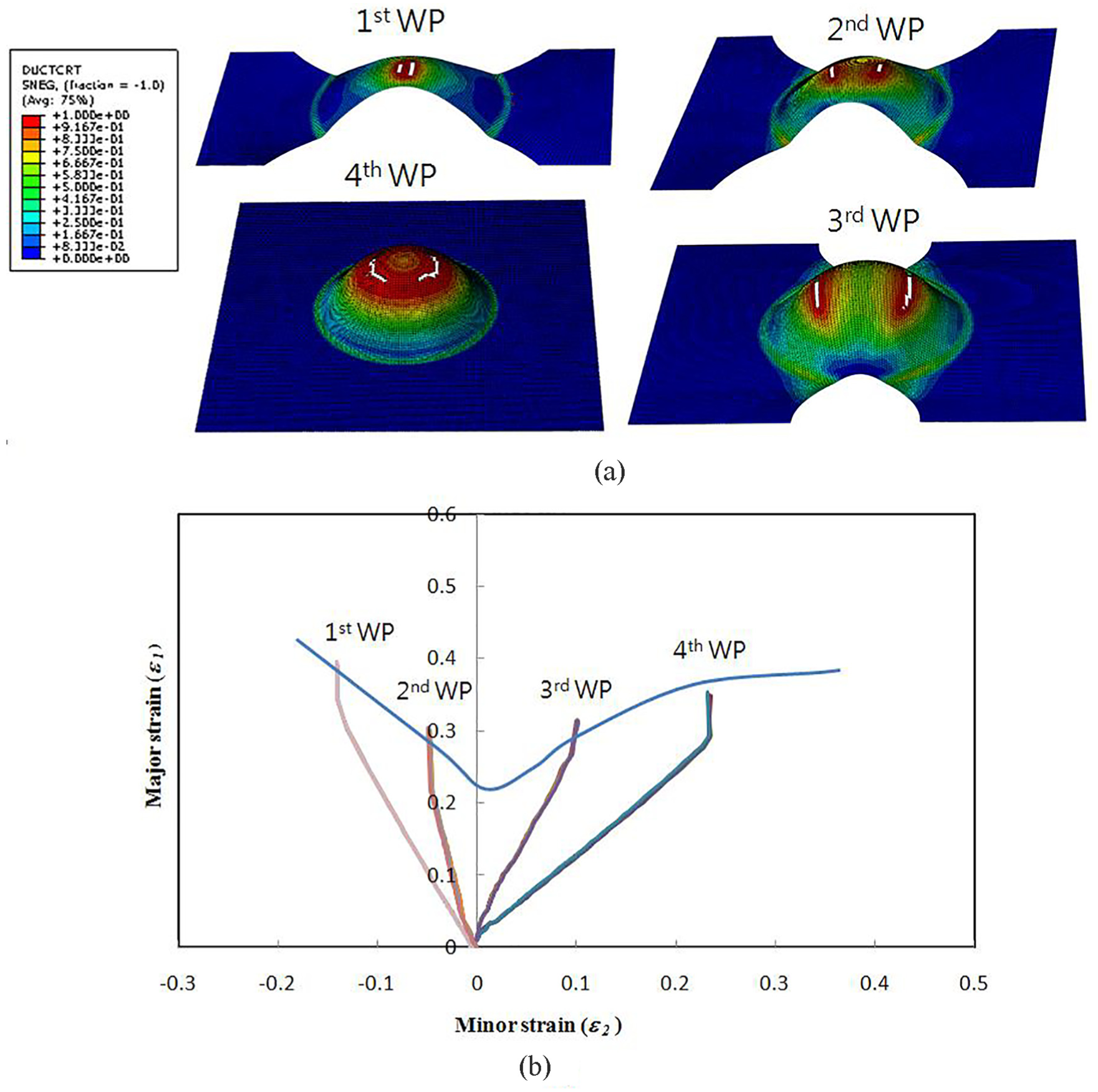
In order to verify forming limit prediction of J-C and ductile void growth criterion (equations (2) and (3)) using FEM simulation results at room temperature, the evolution strain paths (major strain vs minor strain) at the fracture elements of deformed shapes are verified and compared with the experiments of FLD as shown in Figure 14. Both J-C and ductile void growth criterion exhibit good predictions at the left-hand side albeit incorrect prediction at the right-hand side of FLC for the boron steel 22MnB5 sheet at room temperature. This is due to the experimental locations (Figure 8) that are used to calculate fracture criterion by following the J-C and ductile void growth model. The point coordinates after transforming from
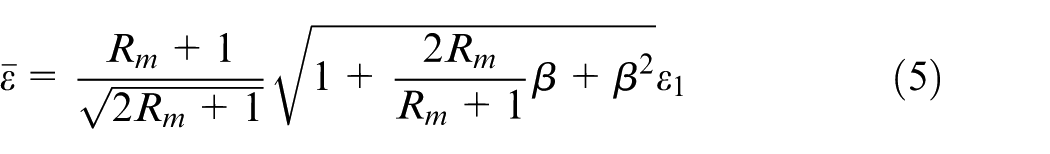
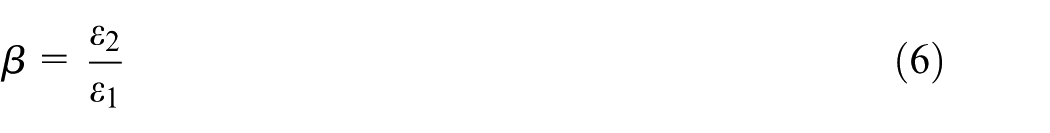
where
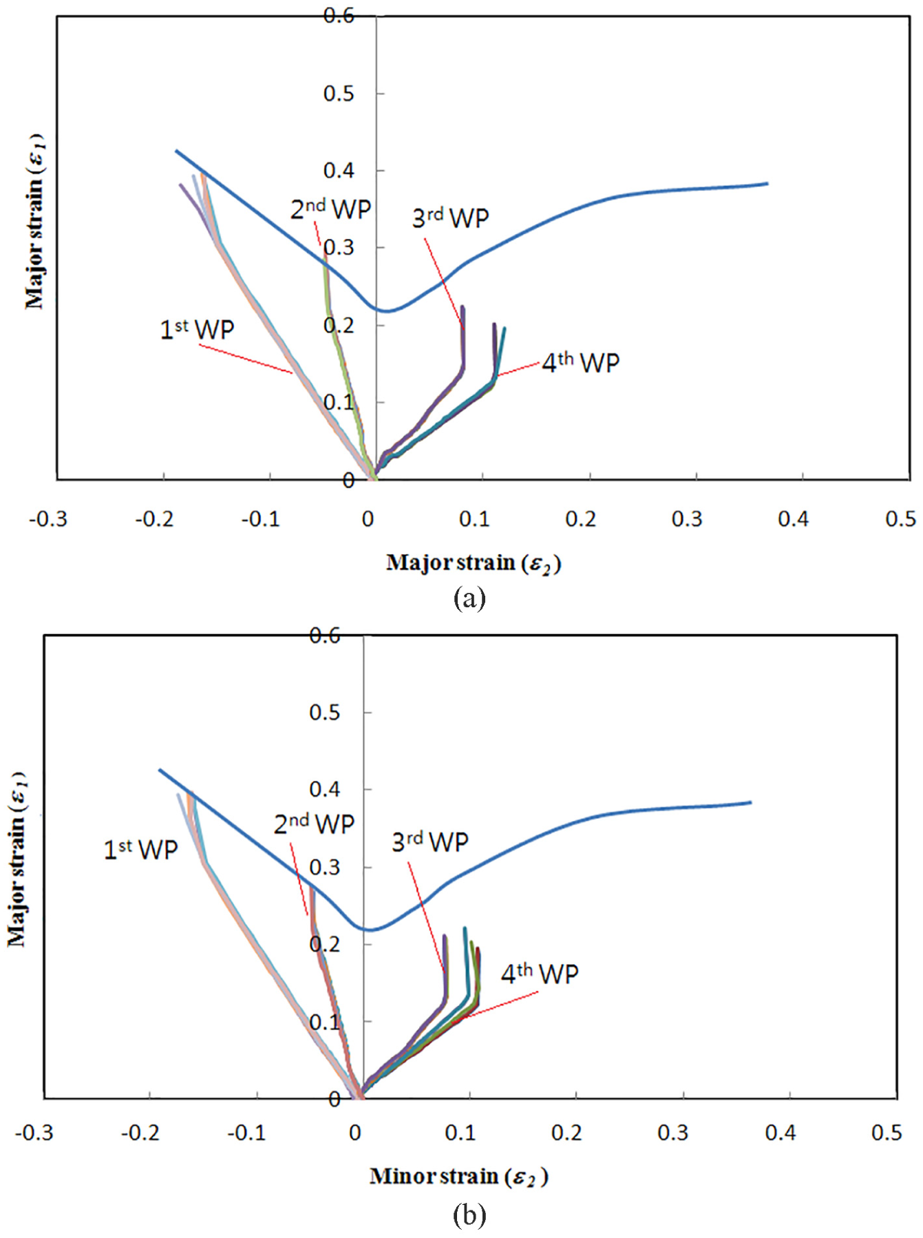
(a) Comparison of the forming limit prediction of J-C and (b) ductile void growth fracture models with experimental FLC data.
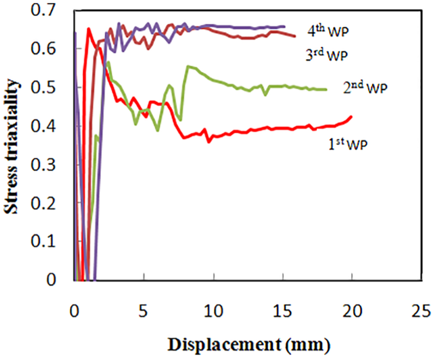
Evolution of stress triaxiality for punch stretching tests.
Fracture strain and corresponding stress triaxiality of punch stretching specimens.
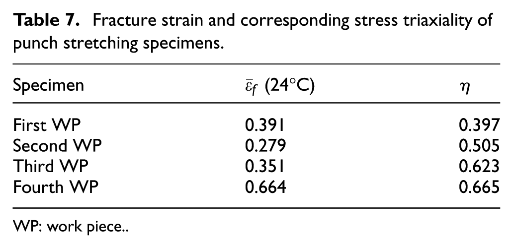
WP: work piece.
In order to determine parameters following ductile void growth model (equation (3)) with more experimental data (Table 7), we utilized a (lsqcurvefit) command in MATLAB software to fit the curve through the relationship of the equivalent plastic strain values at the failure zone versus stress triaxialities. The solution directly shows the calculated values of the calibration parameters c = –2.912, d0 = 0.0015, and d1 = 9.129. The prediction curve with further test data is illustrated and compared with those on previous fracture curves as shown in Figure 16.
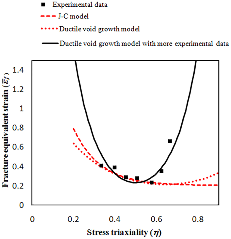
Comparison of the new fracture curve with experimental data and previous fracture curves.
Figure 17(a) shows the results of FEs from the simulation of punch stretching tests with a new FLD. Specifically, the fracture locations of the deformed blank do not fit well with corresponding experiments at room temperature. However, it is not necessary for the measurement of the strain via simulation to improve accuracy by selecting the elements at the top of the hemispherical punch, and thus the strain pairs of failure elements in the deformed blank specimens are also considered and plotted in the
Deformed shape in FE simulations for punch stretching tests by using new fracture curve (a) and comparison of the forming limit between the FE simulation and experiment (b).
FEM simulation prediction at high temperature
In order to estimate FLD for boron steel 22MnB5 sheets at high temperatures, the fracture strain of punch stretching tests at room temperature (Table 7) is first combined with the average ratio
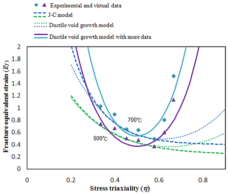
Comparison of the new fracture curve with data and previous fracture curves at high temperatures.
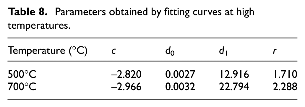
Parameters obtained by fitting curves at high temperatures.
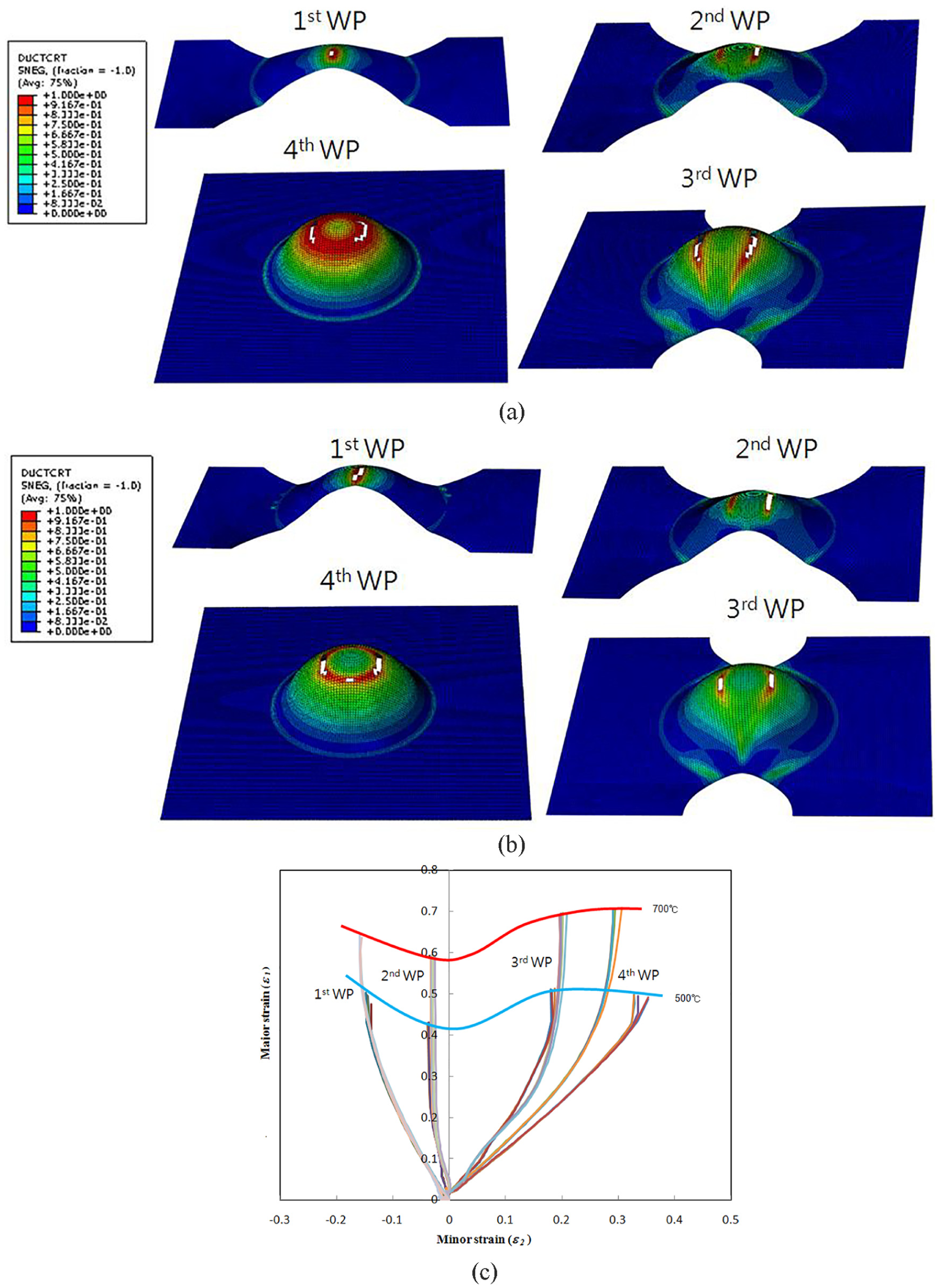
Deformed shape in FE simulations for punch stretching tests at (a) 500°C and (b) 70°C, and (c) their FLC predictions.
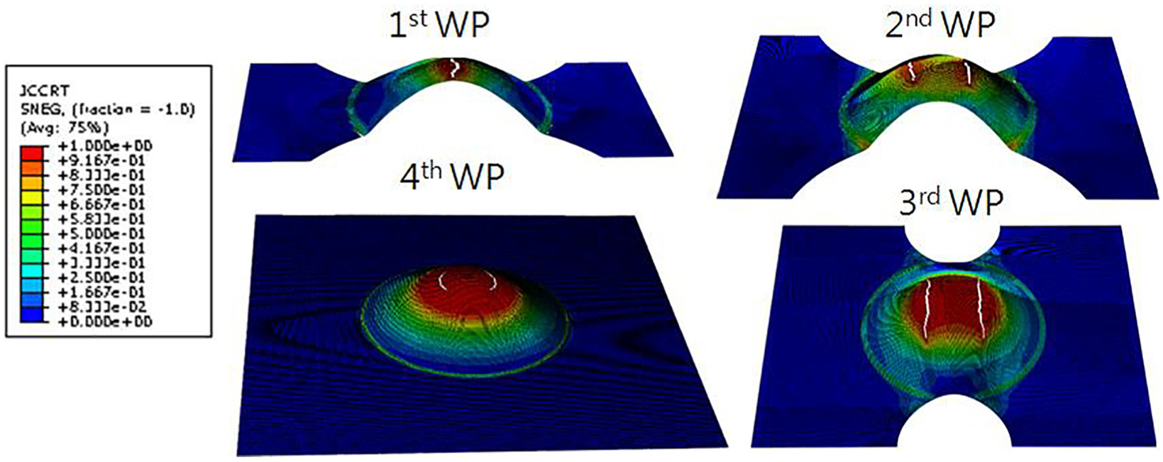
In order to verify the effect of temperature distributions on fracture prediction of specimens during quenching process, a coupled thermo-mechanical computational modeling is applied to simulate punch stretching tests. Figure 20 shows the temperature distribution and evolution in the surface of the first blank specimen (first WP) at various elements after the punch and die quenching process. Specifically, the temperatures from the 700°C specimens are transferred to the punch and die contacting the two sides of the deformed area of specimens at 500°C, 200°C, and 25°C, respectively (Figure 20(a)–(c)). As shown in Figure 20, given the cooling conditions, the remaining temperature in the specimens affects the possibility of fracture locations when compared with that in the isothermal temperature forming condition (Figure 19). In the quenching process, fractures occur in elements corresponding to the highest temperature zone. This is due to the easy deformation of material at higher temperatures. Figure 21 shows the evolutions of strain path at several fracture elements during various quenching conditions from 700°C specimens and compares the same with predicted FLCs at the isothermal temperature corresponding to 700°C. The effects of quenching conditions on the fracture values are low when compared with that for isothermal FLC due to the slow reduction of temperature at the fracture zone. However, strain paths change their direction for the same punch stretching testing specimens due to the movement of fracture to the highest temperature locations in the specimens. Given the effects of cooling condition, fractures occur at elements where the strain path evolutions close to the plane strain zone.
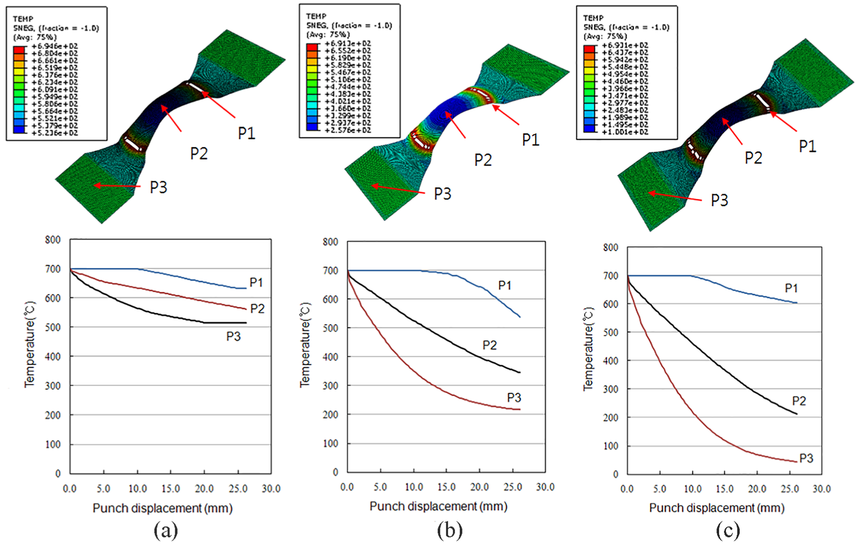
Distribution and evolution of temperature in cooling conditions from 700°C to (a) 500°C, (b) 200°C, and (c) 25°C.
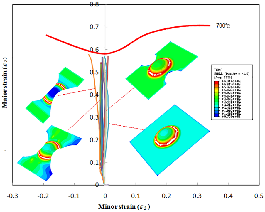
Deformed shapes and strain path evolutions at the fracture zone of various punch stretching specimens in the cooling process.
Experimental and simulation verification
In order to verify the proposed FLD, a plane strain punch for 500°C (developed by Kim et al. 45 ) was used as opposed to a round punch (which was used in previous experiments at room temperature). In the experiments, temperature is verified using a temperature sensor to ensure that the specimen temperature was approximately 500°C during forming. The test is performed with blank-holder force exhibiting a capacity of 15 ton and a maximum punch speed of 300 mm/min. The tensile and plane strain specimens are also verified to compare the deformed shapes at 500°C. Figure 22(a) shows the deformed shapes after experiments, and the corresponding simulations with the evolution of various strain paths at fracture points are shown in Figure 22(b). The results indicate good agreement between the experiment and simulation in terms of both deformed shapes and fracture points.
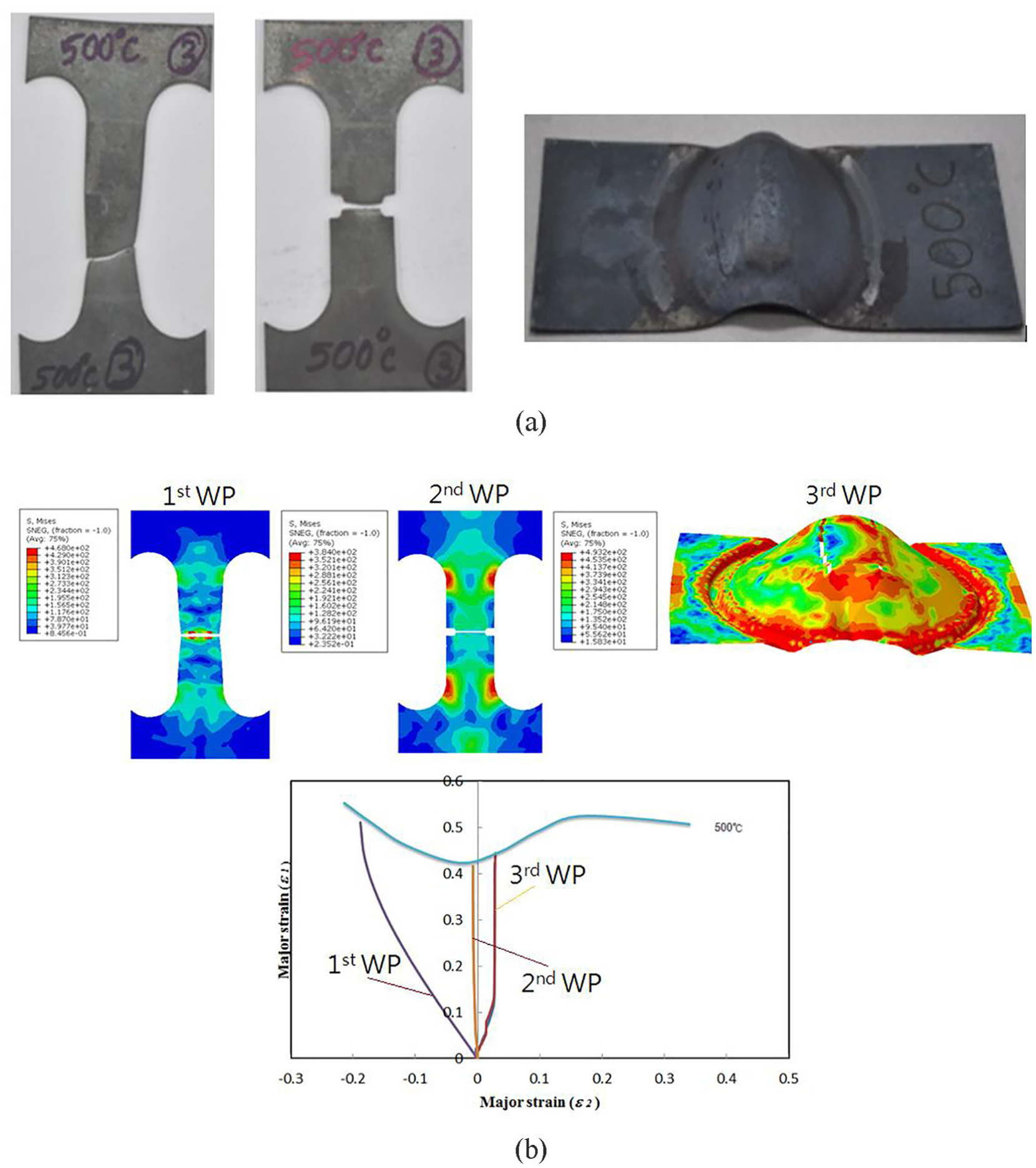
(a) Deformed shapes after experiments and (b) simulations with the evolution of various strain paths at fracture points.
Conclusion
In the study, in order to estimate and predict specific FLDs of boron steel 22MnB5 sheets at high temperatures, ductile fracture criteria were first implemented using FEM simulation and compared with the experimental results of punch stretching tests at room temperature. Subsequently, the prediction of FLD at room temperature was improved by adding stretching test data following the ductile void growth criterion. The model was finally combined with a simple tensile test at high temperatures to predict fracture strain curves and simulate a punch stretching test at elevated temperatures. The FE simulation method results indicated that the proposed method predicts the correct FLC at room temperature and then provides FLD predictions at high and quenching temperatures. Proposed method can be used to predict, elevate, and verify the effect of parameters on the failures of various completed products on HPF via a quenching process.
Footnotes
Declaration of Conflicting Interests
The author(s) declared no potential conflicts of interest with respect to the research, authorship, and/or publication of this article.
Funding
The author(s) disclosed receipt of the following financial support for the research, authorship, and/or publication of this article: This research is funded by the Vietnam National Foundation for Science and Technology Development (NAFOSTED) under grant no.: “107.02-2016.01.”