
Abstract
This work is devoted to anisotropic continuum-damage mechanics in the quasi-static, isothermal, small-strain setting. We propose a framework for anisotropic damage evolution based on the compliance tensor as primary damage variable, in the context of generalized standard models for dissipative solids. Based on the observation that the Hookean strain energy density of linear elasticity is jointly convex in the strain and the compliance tensor, we design thermodynamically consistent anisotropic damage models that satisfy Wulfinghoff’s damage-growth criterion and feature a convex free energy. The latter property permits obtaining mesh-independent results on component scale without the necessity of introducing gradients of the damage field. We introduce the concepts of stress-extraction tensors and damage-hardening functions, implicitly describing a rigorous damage-analogue of yield surfaces in elastoplasticity. These damage surfaces may be combined in a modular fashion and give rise to complex damage-degradation behavior. We discuss how to efficiently integrate Biot’s equation implicitly, and show how to design specific stress-extraction tensors and damage-hardening functions based on Puck’s anisotropic failure criteria. Last but not least we demonstrate the versatility of our proposed model and the efficiency of the integration procedure for a variety of examples of interest.
Keywords
Introduction
State of the art
Damage mechanics describes the progressive degradation of the elastic stiffness of materials upon loading, and is typically attributed to growing voids or cracks on a lower length scale (Lemaitre, 1996), see Figure 1. There are two predominant approaches to continuum damage-mechanics (Krajcinovic, 1984; Lemaitre and Chaboche, 1990). The first approach accounts for the origin of damage on a lower length scale in terms to micromechanics (Fitoussi et al., 1996; Guo et al., 1997), see also Section 3 in Krajcinovic (1989) for an early account. With qualitative predictions in mind, the second strategy is of phenomenological nature. After selecting a suitable damage variable (or a collection thereof), suitable kinetic laws are postulated taking continuum thermodynamics into account, Section 4 in Krajcinovic (1989).
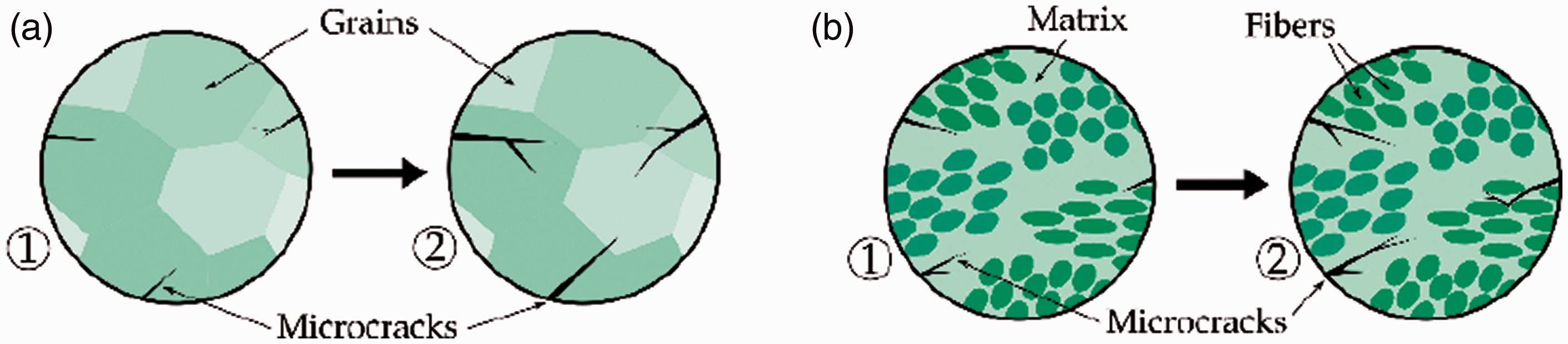
Schematics of microstructures with growing microscopic cracks, passing from state ① to state ②, similar to Fassin et al. (2019). Growing microcracks induce a reduction of the effective stiffness. (a) Polycrystalline microstructure. (b) Microstructure composed of fiber bundles.
The micromechanics-based approach to damage mechanics takes the damage mechanisms on a lower scale into account and is still subject of current research, for instance concerning mesh-size objective modeling (Liang et al., 2018), a coupling to model-order reduction (Bhattacharyya et al., 2020) or accounting for micro-computed tomography data (Luo et al., 2020). Micromechanics-informed damage models permit taking the stochastics on the microscale into account naturally, e. g., for progressive fiber breakage in fiber-reinforced composites (Ju and Wu, 2016; Wu and Ju, 2017), interfacial transition-zone effects (Chen et al., 2018), uncertainty in the elastic moduli of fiber-reinforced concrete (Liu et al., 2020), localized microcracks (Li et al., 2020) or random loading in fatigue processes (Franko et al., 2017). Another advantage concerns modeling the unilateral character of brittle damage, i. e., a different damaging behavior under tension compared to compression (Goidescu et al., 2015; Zhang et al., 2019), and accounting for interface debonding (Pupurs and Varna, 2017; Schemmann et al., 2018b; Yang et al., 2020). However, care has to be taken as homogenization and localization are incompatible (Gitman et al., 2007), in general, i.e., upon localization, the volume elements considered will not be representative for the effective mechanical behavior (Drugan and Willis, 1996; Hill, 1963; Kanit et al., 2003).
As an alternative to micromechanics-type strategies, phenomenological approaches to continuum-damage mechanics may be pursued. In a first step, a (scalar- or tensor-valued) damage variable is selected which describes the reduction of the effective cross-section of a typical material sample undergoing material degradation (Gurson, 1977; Voyiadjis, 2015). Then, suitable kinetic laws are postulated on the basis of continuum thermodynamics (Hansen and Schreyer, 1994; Simo and Ju, 1987).
The tensor order of the damage variable naturally distinguishes different phenomenological damage models. Even today, the classical scalar isotropic damage variable serves as a reliable workhorse with numerous applications including cast steel with pores (Yan et al., 2020), concrete (Li and Wu, 2018), rocks (Liu et al., 2018; Xu et al., 2018), framed structures (Yang et al., 2017), unidirectional glass fiber-reinforced plastic composite plies (Sharma and Daggumati, 2020), fibrous composite laminae (Abu-Farsakh and Asfa, 2020), notched epoxy resin specimens (Rahimi et al., 2020) and steel-fiber reinforced concrete (Moradi et al., 2020).
Damage variables with higher tensor order permit modeling an emerging anisotropy of damage. As working with second-order tensors comes naturally to disciples of continuum mechanics, it is not surprising that second-order damage-tensors (Murakami and Ohno, 1981) are used frequently in continuum damage-mechanics. Recent applications include concrete (Desmorat, 2016; Wardeh and Toutanji, 2017), metal-forming processes (Nasab and Mashayekhi, 2019), rock materials (Wang and Xu, 2020), composite fabrics and laminated panels (Wei et al., 2020) and composite laminates (Okabe et al., 2018; Onodera and Okabe, 2020). Second-order damage-tensors are always orthotropic w. r. t. their eigenbasis, limiting their degree of generality. More often than not, such a limitation is interpreted as a feature, and specific orthotropic damage models are developed, for instance for brittle materials (Kim et al., 2016), in elastoplastic and finite-strain damage coupling (Ganjiani, 2018; Reese et al., 2021), or for ceramic-matrix composites (Alabdullah and Ghoniem, 2020).
As continuum damage-models primarily seek to describe a loss of stiffness due to emerging defects in solids, using a fourth-order damage-tensor (Chaboche, 1981), the same tensor order as the stiffness tensor, appears reasonable. In Section 4.3.4, Krajcinovic (1989) even notes that “an appropriate description of damage […] must involve at least a fourth-rank tensor.” This idea was pursued for the stiffness or compliance tensors as the primary damage variable (Dougill, 1976; Ortiz, 1985; Ortiz and Popov, 1982), also coupled to plasticity (Ju, 1989; Simo and Ju, 1987; Yazdani and Schreyer, 1990). We refer to Zhang and Cai (2010) for a modern account of anisotropic damage mechanics. However, some care has to be taken when working with tensor-valued damage variables due to possible inconsistencies arising for complex non-radial loading-unloading scenarios, see Simon et al. (2017).
The unilateral character of pores and cracks (see Figure 1) often leads to a tension-compression asymmetry of the material behavior upon damage loading, see Chaboche (1993) for a discussion. To incorporate the latter effect in phenomenological models, one may introduce different damage variables for the tensile and the compressive regime (Cicekli et al., 2007; Ramtani et al., 1992). For three-dimensional stress states, spectral decompositions of either the strain or the stress tensor may form the basis of continuum damage models that differentiate between damage evolution due to tension and compression (Ladeveze and Lemaitre, 1984; Ortiz, 1985).
Whenever damage models exhibit a softening behavior, their use in a continuum formulation leads to an ill-posed problem due to localization effects (Lemaitre, 1986), which is reflected by strongly mesh-dependent results in numerical simulations (De Borst, 1996). Countermeasures in the framework of local damage models were investigated (Becker et al., 1988; Beremin et al., 1983; Tvergaard, 1982). Non-local formulations (Bažant, 1991; Belytschko et al., 1986) prevent the localization responsible for the ill-posedness, and may be realized by an explicit convolution with a tapering function (Pijaudier-Cabot and Bažant, 1987), by augmenting the damage evolution equation by an elliptic differential operator (Aifantis, 1984) or by employing a gradient-enhanced formulation (Abu Al-Rub and Voyiadjis, 2009; Brünig and Ricci, 2005; Germain et al., 2007), which may also be coupled to Hamilton’s least-action principle (Junker et al., 2019, 2021). As long as the softening is not too pronounced, existence of results for non-local damage models (Thomas and Mielke, 2010) may be established. However, except for specific models (Roubíček, 2009; Susu, 2017), uniqueness (and, thus, well-posedness) cannot be ensured. For a review on ill-posedness due to localization problems and appropriate regularization methods, the reader is referred to Forest et al. (2004). Also, for a general overview on continuum damage-mechanics and further literature, the reader may consult the books of Murakami (2012) and of Voyiadjis (2015).
Oftentimes, the ill-posedness of local damage models is taken for granted, and appropriate countermeasures are taken. A charming strategy takes a conventional local damage model with softening (but sufficient growth at infinity), and applies relaxation techniques (Balzani and Ortiz, 2012; Schmidt and Balzani, 2016; Schwarz et al., 2021), which are typically used for studying solids with emerging microstructure. When describing stable damage processes, these countermeasures should not be neccesary, however. Indeed, for a moderate degree of loading, localization is excluded, and manifests only at a specific turning point in loading level. For component-scale simulations, this loading level is not readily apparent, and depends on the specimen geometry via solving the equations of continuum mechanics. To sum up and loosely speaking, we know that local damage models are perfectly reasonable up to a specific level of loading, but we do not know this level in advance. Thus, interest arose to design damage models which give rise to a meaningful response for the entire range of loading, and which are intended to be complemented by a classical failure criterion.
Contributions and organization of this article
We contribute to phenomenological continuum damage-mechanics with a tensorial damage variable. We advocate using the full compliance tensor as a rather natural and observable damage variable, liberating the engineer of the burden of selecting the appropriate damage variable in advance, permitting her to focus the attention on appropriate kinetic laws. Thus, when it comes to continuum damage-mechanics of phenomenological type, the proposed framework is as ab-initio as possible, since only the evolution of the damage surface in stress space needs to be identified.
The compliance tensor has been used as the primary damage variable before (Baranger, 2018; Ladevèze, 1983, 2002; Ladevèze et al., 2014). Yet, this approach has not yet entered the main stream of damage-modeling frameworks. Our theoretical contributions to compliance-based damage models are actually twofold. For a start, we point out that the standard Hookean strain energy density, regarded as a function of the strain tensor and the full compliance tensor, is de facto jointly convex in both arguments. This result is surprising, and we are not aware of an account in the literature (although we sincerely believe that others have presumably noticed this fact before without stating it explicitly, see Thomas and Mielke (2010) for a special case).
Based on the compliance tensor, we develop a simple, modular framework for anisotropic damage mechanics. The framework provides the working engineer with a number of options which we believe to be of advantage. Indeed, due to the convexity property of the Hookean elastic energy, it is possible to develop a purely hardening damage-mechanics modeling-framework, where localization does not become an issue. Very much, there are materials which show a purely damage-hardening material response prior to sudden and brutal failure, e.g., Sheet Molding Compound (SMC) composites (Anagnostou et al., 2018; Fitoussi et al., 1996, 1998) comprising an unsaturated polyester-polyurethane hybrid (UPPH) resin (Kehrer et al., 2018; Schemmann et al., 2018a; Trauth et al., 2017) reinforced by glass fibers (Görthofer et al., 2019; Meraghni and Benzeggagh, 1995; Schemmann et al., 2018c).
Of course, the modeling framework is not restricted to damage-hardening, but may be adapted to softening in a straightforward manner. However, the latter scenario is rather classical in continuum damage-mechanics, and we decided to work out the details of a hardening framework in the paper at hand, essentially due to our desire to model SMC materials.
To highlight the simplicity of our proposed compliance-type damage modeling framework, we present a first-principles development in the context of generalized standard models (GSMs) for dissipative solids (Halphen and Nguyen, 1975) and discuss the efficient resolution of the evolution equations in a predictor-corrector framework.
Our second contribution concerns a design methodology for the damage surfaces which draws upon similar approaches in (associative) elastoplasticity (Bertram, 2011; Chaboche, 2008; McDowell, 2008), but takes failure criteria and multiple damage surfaces (Bakhshan et al., 2018; Jin and Arson, 2018; Khayyam Rayeni et al., 2020) into account. More precisely, building upon Puck’s anisotropic failure criteria developed for continuously reinforced polymers (Knops, 2008; Puck and Schürmann, 2002), we design specific damage-extraction tensors and damage-activation functions which present a flexible arsenal of tools that, taking the individual damaging mechanisms into consideration, permit building up an accurate and fully anisotropic continuum damage model.
For anisotropic damage models not to be judged as purely academic, it is of utmost importance to establish links to experimental data and to compare it to (dis)similar modeling approaches. After conducting computational investigations which clarify the influence of the different model parameters on the damage evolution and expose the developing elastic anisotropy upon loading, we study a plain-weave mesostructure of a woven carbon-fiber reinforced thermoset investigated by Simon et al. (2017). We show that the convex modeling framework permits reproducing the effective mechanical behavior of the individual tows and the composite quantitatively within the loading range of interest.
Notation
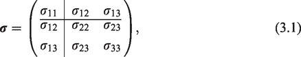
We follow a direct tensor notation throughout the text, representing vectors and tensors by their components or using matrix representations (in an orthonormal basis) only when necessary. Vectors and second-order tensors are denoted by lower case and upper case bold letters, respectively (e.g.,
A compliance-based anisotropic damage model
A convex standard model for anisotropic damage
We will describe the damage model, in a small-strain and isothermal setting, as a generalized standard model (GSM) (Halphen and Nguyen, 1975), whose framework we briefly recall. In addition to the symmetric


For a prescribed loading path
where


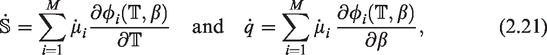
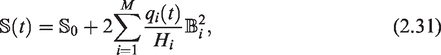
As internal variables z of our proposed continuum damage-mechanics model, we consider an elastic compliance tensor


Notice that the set
For a GSM, the CDI (2.2) will always be satisfied. However, we need to ensure that the (dual) Biot’s equation (2.4) guarantees that
The free energy (density) we consider is defined by


Using the framework of generalized standard materials for phenomenological modeling of damage is classical. For instance, Hansen and Schreyer (1994) study a general tensor-valued damage variable coupled to plasticity in such a framework, apparently unaware of the connection.
In phenomenological continuum damage-mechanics, choosing the damage variable typically comes first, and the damage kinetics needs to be set up based on the resulting driving forces. Our approach frees the reader of an a priori selection of damage variable, and permits her to focus on the kinetics in terms of the quite natural stress-based driving force.
The compliance tensor has the attractive characteristic that it is a physical quantity which can be determined experimentally. Of course, determining all 21 independent parameters of a stiffness tensor in three spatial dimensions is a daunting task from an experimental perspective. Still, observability of the damage variable is not ensured for purely phenomenological damage vectors and tensors.
The compliance tensor has been used as a damage variable before (Ladevèze, 1983, 2002). However, its use seemed restricted to specific situations, e.g., damage modeling in ceramic-matrix composites (Baranger, 2018; Ladevèze et al., 2014). In this work, we advocate using the compliance tensor as the damage variable of choice in greater generality.
It is more than well-known that the Hookean energy (2.11) is convex in the strain tensor. It appears much less known that the Hookean energy is jointly convex in the strain and the compliance tensor. When coupled to an energy h which makes the condensed incremental potential strictly convex, the resulting framework produces an anisotropic damage model which does not permit localization. In particular, associated finite-element computations are not affected by mesh sensitivity induced by softening behavior. We do not want to argue against damage localization. Rather, we wish to add a powerful weapon to the arsenal of continuum damage-mechanics when it comes to modeling stable anisotropic damage phenomena.
In classical small-strain elasto(visco)plasticity the (visco)plastic strain

with a fixed stiffness tensor 7. If we regard the Hookean elastic stored energy function

which may become negative (take, for instance 8. For the thermodynamics considerations at the beginning of this section to be valid, the “interfacial” energy (2.12) need not be convex, see, for example, Govindjee et al. (1995). In particular, softening behavior can be modeled in the compliance-tensor framework, as well. In that case, for obtaining a well-defined boundary-value problem, damage localization has to be overcome, for instance by adding gradient terms of the variable q to the energy (2.12). 9. The presented model cannot distinguish tensile and compressive loading. Indeed, the driving force

which is insensitive to the involution
To finish presenting the two-potential model, a suitable force potential

In the quasi-static setting targeting a rate-independent damage model, we describe the force potential

Such a force potential gives rise to a quasi-static damage evolution in terms of an elastic domain defined by the functions
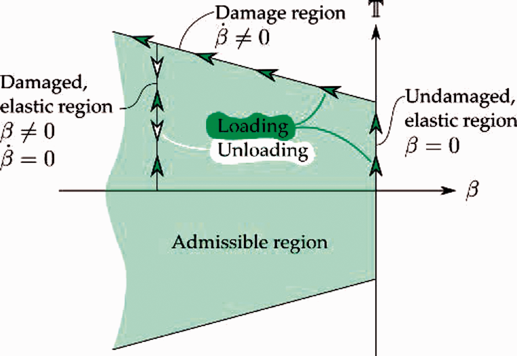
Schematic of the admissible elastic region in (
However, some care has to be exercised, as the elastic domain is defined in terms of the compliance driving-force


To ensure that

on the damage functions
To complete describing our model, we restrict the space of damage variables to

In principle, the damage-extraction tensor
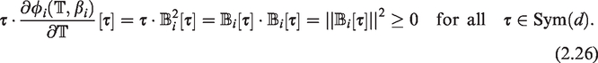
In any case, for the damage function (2.25) the condition (2.24) to fulfill Wulfinghoff’s damage growth criterion, is automatically satisfied. Indeed, for any
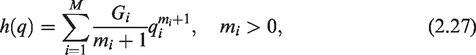
In addition to the damage functions, we assume a hardening-type damage-surface potential of power-law type

In view of the force potential

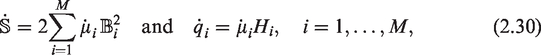
Several simplifications are in order. First, notice that the parameters Gi and Hi only enter (2.29) as the product


Computational predictor-corrector framework
In this section, upon an implicit Euler discretization in time, we discuss a predictor-corrector solution strategy for the model introduced in the previous section in strict analogy to associative elastoplasticity, see Chapter 2 in Simo and Hughes (1998). Suppose that a number of discrete time steps
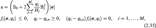

We solve the latter problem by an active set strategy (Bergounioux et al., 1999, 2000), i.e., by solving the system (2.37) with a Newton method, updating the currently active set at each Newton iteration and accounting for the constraints
As long as the damage constraints are linearly independent, due to the established connections of active set strategies to semi-smooth Newton methods, see Hintermüller et al. (2002), a locally superlinear convergence behavior can be expected. A schematic of the predictor-corrector strategy is shown in Figure 3 with
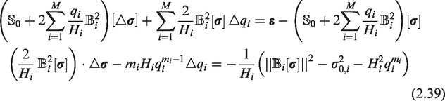
For solving problem (2.37), we assemble the Newton system for the active set
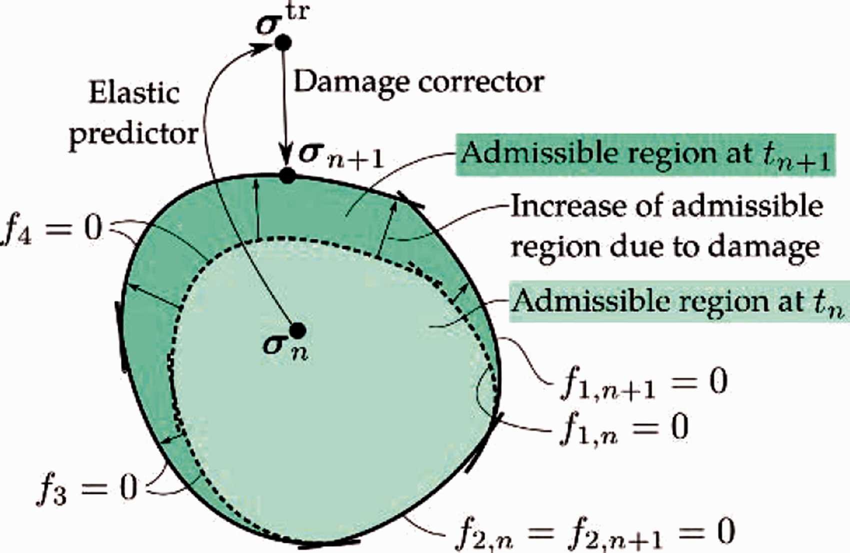
Evolution of the elastic region upon loading within a predictor-corrector framework.
1:
2:
3:
4:
5: no damage evolution, elastic predictor step correct
6:
7:
8:
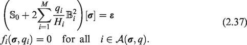
9: Update residual (2.38)
10:
11:
12: assemble and solve the Newton system (2.39) for
13:
14:
15:
16:
17: Update residual (2.38)
18:
19:
20:
21: Update residual (2.38)
22:
23:
24:
25:
26:
27: compute
28:
29:
Damage models with Puck-type extraction tensors
Basic idea
Puck (Knops, 2008; Puck and Schürmann, 2002) introduced strength-estimation models for composites reinforced by continuous fibers based on specfic failure scenarios that are commonly observed in post-critical investigations of failed specimens. For the current article at hand, we will use these so-called Puck cases as primary drivers of the anisotropic damage evolution presented in the previous section. More precisely, we will investigate the Puck cases individually, and determine proper extraction tensors (
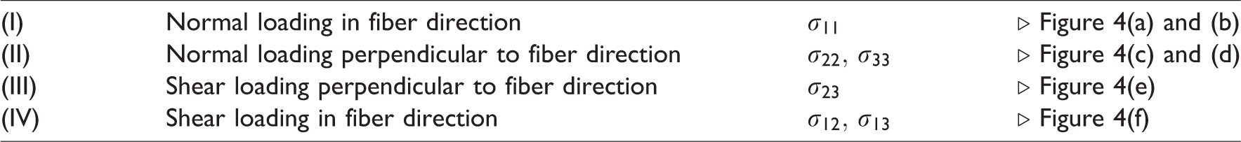

Regions of major damage (blue) resulting from different loading scenarios in a cell with aligned fibers (dark green). (a) Extension in fiber direction. (b) Compression in fiber direction. (c) Extension ⊥ to fiber direction. (d) Compression ⊥ to fiber direction. (e) Shearing ⊥ to fiber direction. (f) Shearing in fiber direction.
The loading scenarios shown in Figure 4 are only examples, e.g., loadings perpendicular to the fiber direction need not necessarily follow direction
Case I: Normal loading in fiber direction
The first damage case is governed by loading in fiber or bundle direction, respectively, and thus solely concerns the stress 
The associated damage function 
Case II: Normal loading perpendicular to fiber direction
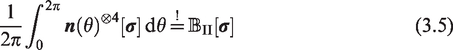
To quantify damaging due to normal loading in any direction 
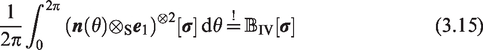
The latter average may be represented in the form

Evaluating the integral explicitly, see Appendix C for details, yields

This extraction tensor 
Case III: Shear loading perpendicular to fiber direction
In addition to damage caused by normal loading, we also want to account for shear-loading induced damage. For a general stress state 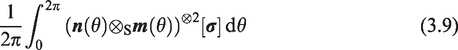

We may rewrite this expression
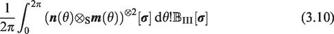
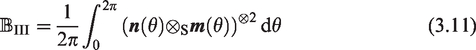

Explicitly evaluating the integral (3.11) yields

The damage function 
Comparing the extraction tensors
Case IV: Shear loading in fiber direction
To evaluate damage induced by shearing in fiber direction 

The resulting extraction tensor for case IV may be expressed via

The damage function 
Computational investigations
Setup
We integrated the proposed damage model as a user-defined subroutine into an in-house OpenMP-parallel FFT-based computational homogenization code written in Python 3.7 with Cython extensions (Behnel et al., 2011) and FFTW (Frigo and Johnson, 2005) bindings, as described, e.g., by Schneider (2019). The balance of linear momentum was discretized on a staggered grid (Schneider et al., 2016b) and the ensuing nonlinear systems of equations were solved by a Newton-CG scheme (Gélébart and Mondon-Cancel, 2013; Kabel et al., 2014; Wicht et al., 2020). The computations ran on 6 - 12 threads on a desktop computer with 32 GB RAM and an Intel i7-8700K CPU with 6 cores and a clock rate of 3.7 GHz. The plain-weave presented at the end of this section was computed on a workstation with two AMD EPYC 7642 and 48 physical cores each, enabled SMT, and 1024 GB of DRAM.
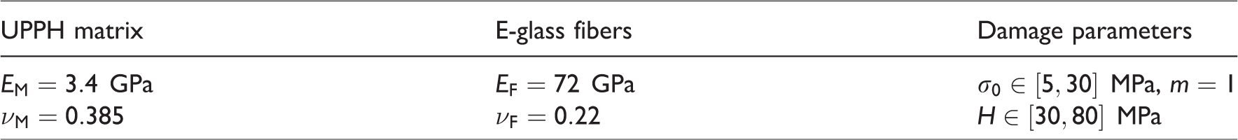
For the following studies, we use the isotropic elastic parameters of unsaturated polyester-polyurethane hybrid (UPPH) resin and E-glass fibers, see Kehrer et al. (2018), respectively, if not specified otherwise. Furthermore, we use the damage parameters
Standard material parameters (Kehrer et al., 2018) and reference damage parameters, serving as point of departure depending on the corresponding damage case.
Numerical studies on integration-point level
Parameter study for Puck-type extraction tensor I
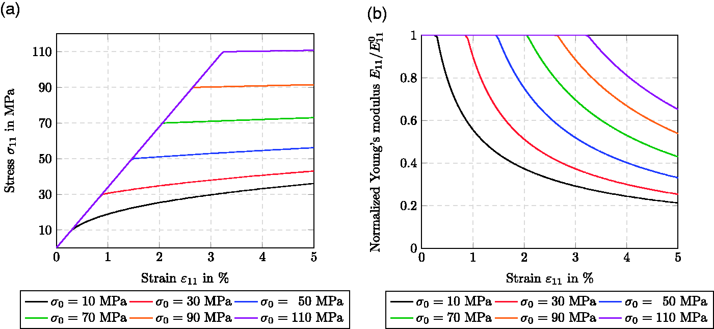
The first study concerns the effects of the damage parameters
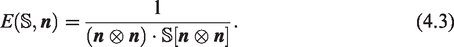
For the case at hand, we extract the current Young’s modulus in 
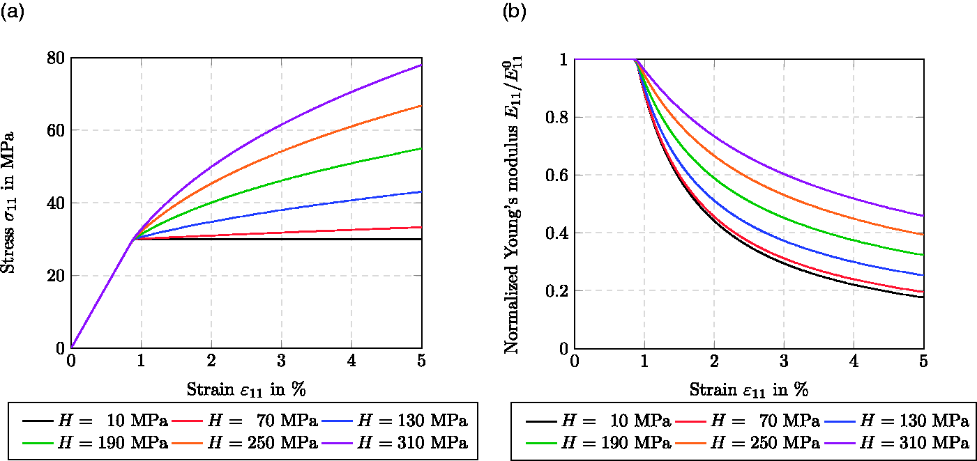
The influence of the damage-activation threshold
With increasing damage-activation thresholds
Due to the thermodynamically consistent GSM framework of our proposed model, an upper bound for the damage variables is ensured, governing the asymptotic behavior of the (normalized) stiffness reduction, see Figure 5(b). Evaluating the CDI (2.2) for the considered case at hand, we find the upper bound for the damage variable w. r. t. Puck case I to be
The effect of changing the hardening parameter H on the stress and damage evolution is shown in Figure 6. As the damage-activation threshold
In the damage region, the slope of the stress-strain curve increases with the hardening parameter H. Indeed, the hardening parameter H describes the hardening capacity of the model. For
Independent of the hardening parameter, damage evolution initiates at the same strain level (and therefore the same stress level), see Figure 6(b). The stiffness reduction is inversely proportional to the hardening parameter H.
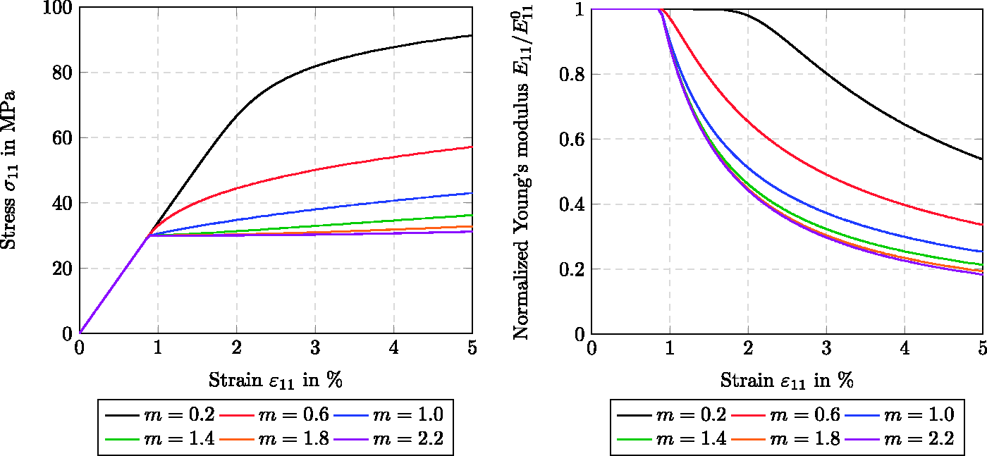
In Figure 7, we fix the damage-activation threshold
For increasing exponents m, the stress-strain curves approach the plateau-like behavior. For small values of m, after exceeding the damage-activation threshold
Figure 7(b) shows the damage evolution to be inversely proportional to the exponent m, leading to a lower remaining (normalized) stiffness component
For representing the stiffness tensor 
Varying the initial stress
Varying the hardening parameter
Varying the power-law exponent
Asymmetry properties of the stiffness tensor
Examples of such YMS plots are shown in Figure 8. The initially isotropic stiffness tensor with UPPH material parameters (see Table 1) has a spherical shape, as shown in Figure 8(a). As discussed above, the induced damage model based on Puck case I leads to a reduction of the stiffness
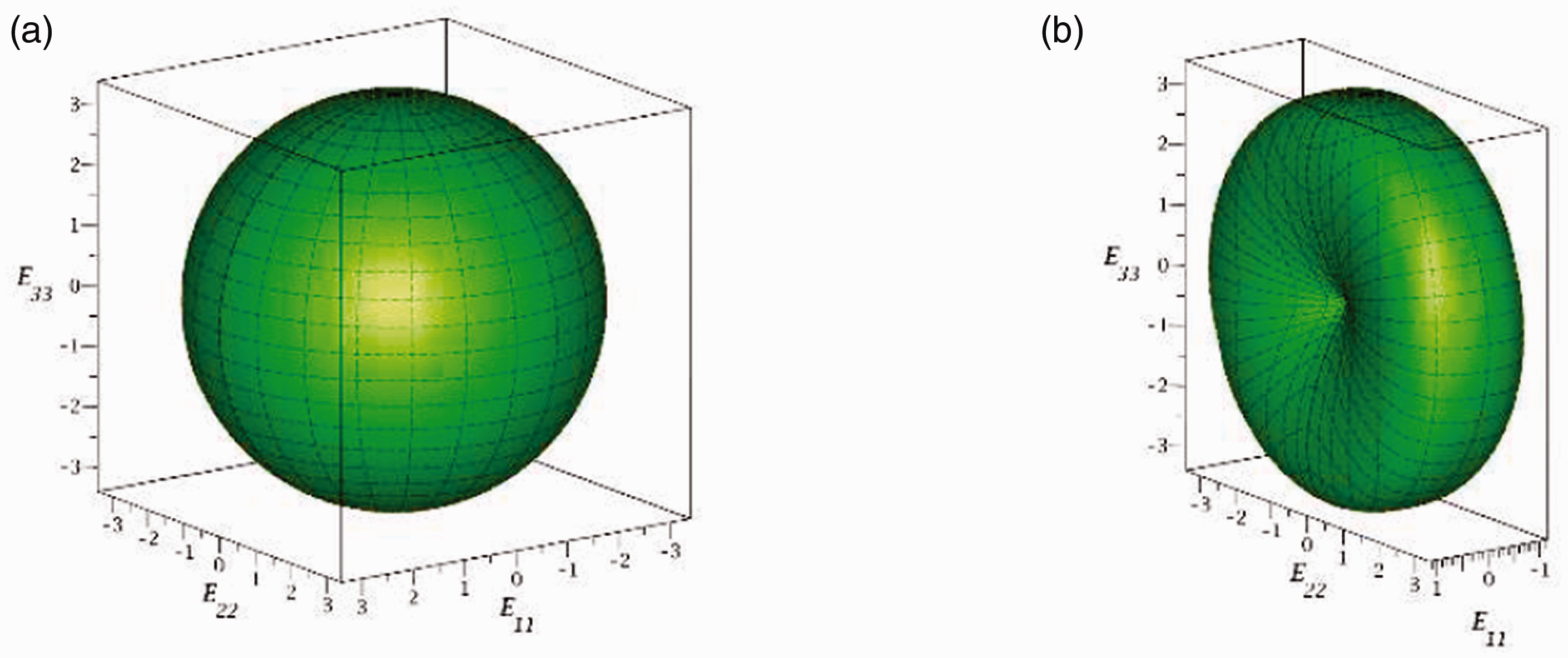
YMS plots (see Böhlke and Brüggemann, 2001) showing the reduction of the stiffness tensor based on Puck case I. (a) Initial isotropic state. (b) Final anisotropic state.
Stiffness reduction for different Puck-type extraction tensors
In the following, we will discuss possible damage evolutions and corresponding stiffness reductions based on Puck-type extraction tensors II, III and IV. For these cases, the influence of the damage-hardening parameters
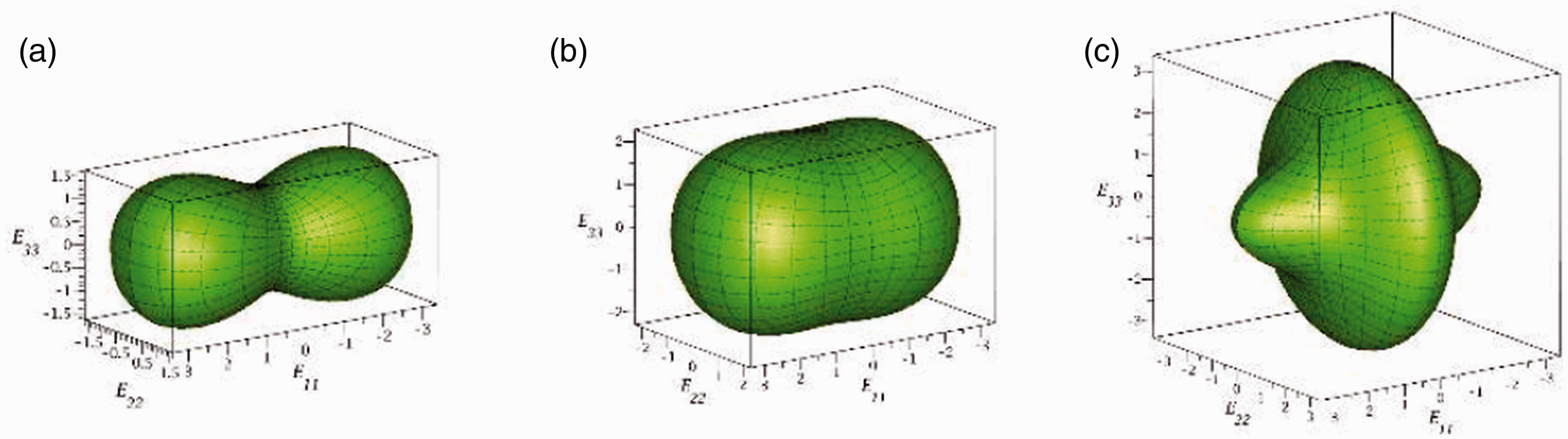
YMS plots (see Böhlke and Brüggemann, 2001) illustrating the reduction of the stiffness tensor based on the Puck cases II, III and IV. (a) Case II. (b) Case III. (c) Case IV.
Non-monotonic loading
To show the capabilities of our model in general, we perform loading-unloading experiments for different loading directions in a successive fashion. To mimic uniaxial normal loadings and corresponding shear loadings, we subsequently apply normal and shear strains
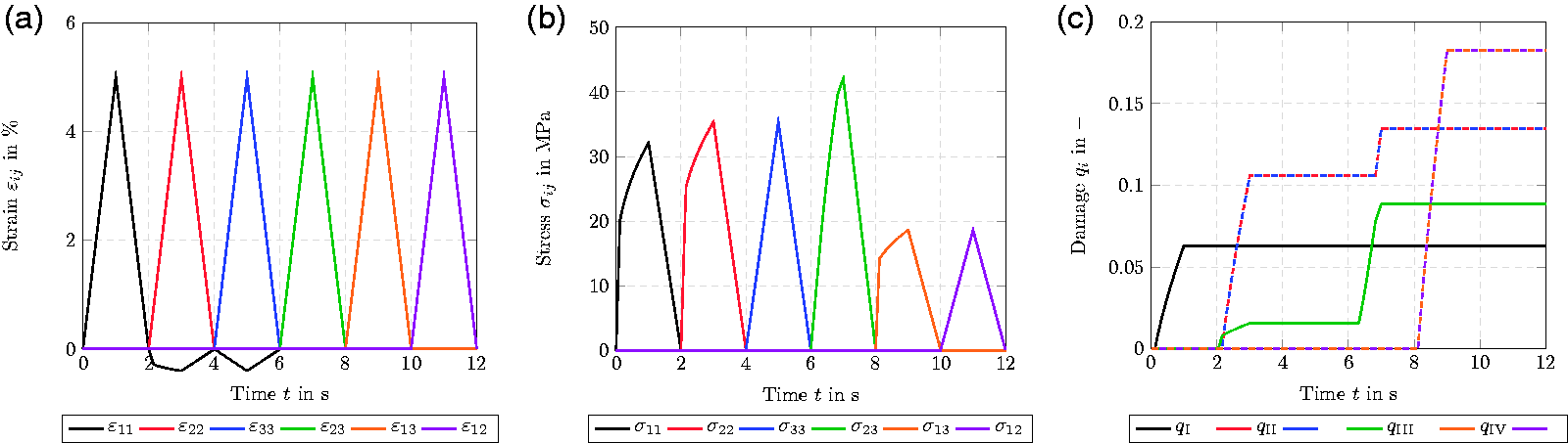
Complex loading history addressing each stress-tensor component separately. (a) Strain vs. time. (b) Stress vs. time. (c) Damage evolution over time.
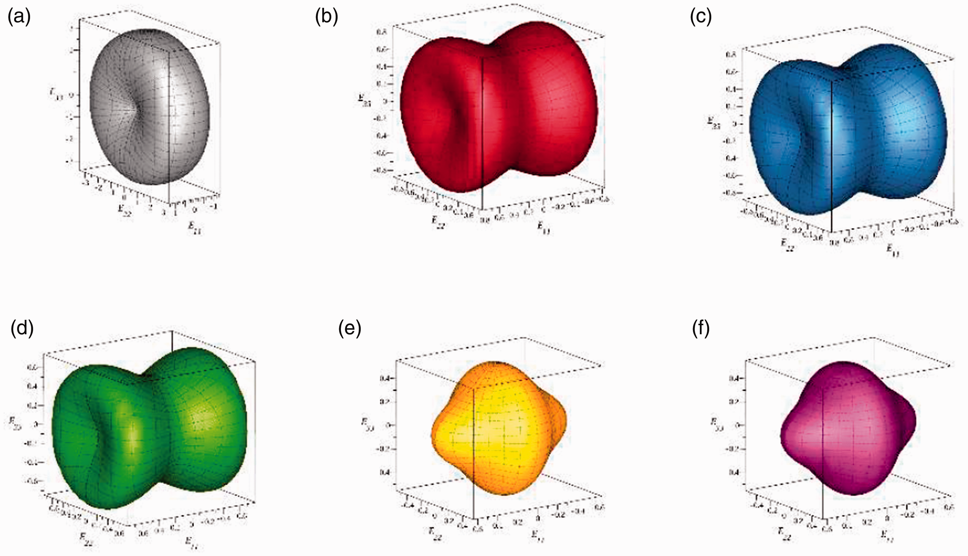
Evolution of an initially isotropic stiffness upon complex loading, see Figure 10(a), visualized via YMS plots. (a) After loading step 1 (ε11). (b) After loading step 2 (ε11 and ε22). (c) After loading step 3 (ε11, ε22 and ε33). (d) After loading step 4 (ε11, ε22, ε33 and ε23). (e) After loading step 5 (ε11, ε22, ε33, ε23 and ε13). (f) After loading step 6 (ε11, ε22, ε33, ε23, ε13 and ε12).
These observations are also reflected in the damage evolution, see Figure 10(c). Due to the applied stress
Comparing Figure 11(b) and (c), as well as Figure 11(e) and (f), we see that, in accordance with Figure 10(c), no further damage is induced between these loading steps. The presented YMS plots demonstrate the capability of our model to evolve the stiffness tensor in a complex and anisotropic way. The model is capable of handling any initial stiffness, not restricted by a specific symmetry class, i.e., transversely isotropic or orthotropic. Furthermore, the stiffness tensor may also develop anisotropy - within the permissible set
Multiaxial loading with increasing loading level
In a study combining the six loading steps from the previous section to one superposed loading case, we apply a three-dimensional strain state s. t. all strains are active simultaneously. To investigate the model behavior, the predicted stiffness degradation, as well as the evolution of the damage variables more closely, we gradually increase the strain levels in five steps from 0% to 5% via 1% increments with intermediate unloading, see Figure 12(a). As in the previous section, we analyze the stress and the damage evolution, as well as the stiffness reduction. Figure 12(b) shows the evolution of the individual stress components during the combined loading. We see that after each loading-unloading step the level of damage increases. This is also reflected in the evolution of the damage variables, see Figure 12(c). After each loading-unloading step, the damage variables continue to increase whenever the maximum stresses of the previous step are exceeded. The YMS plots corresponding to
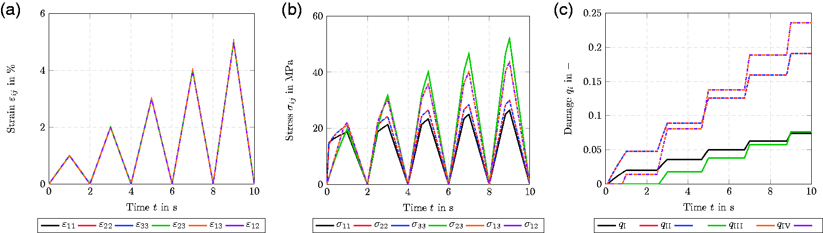
Step wise increase of multiaxial loading to evoke all stresses and damage functions simultaneously. (a) Strain vs. time. (b) Stress vs. time. (c) Damage evolution over time.
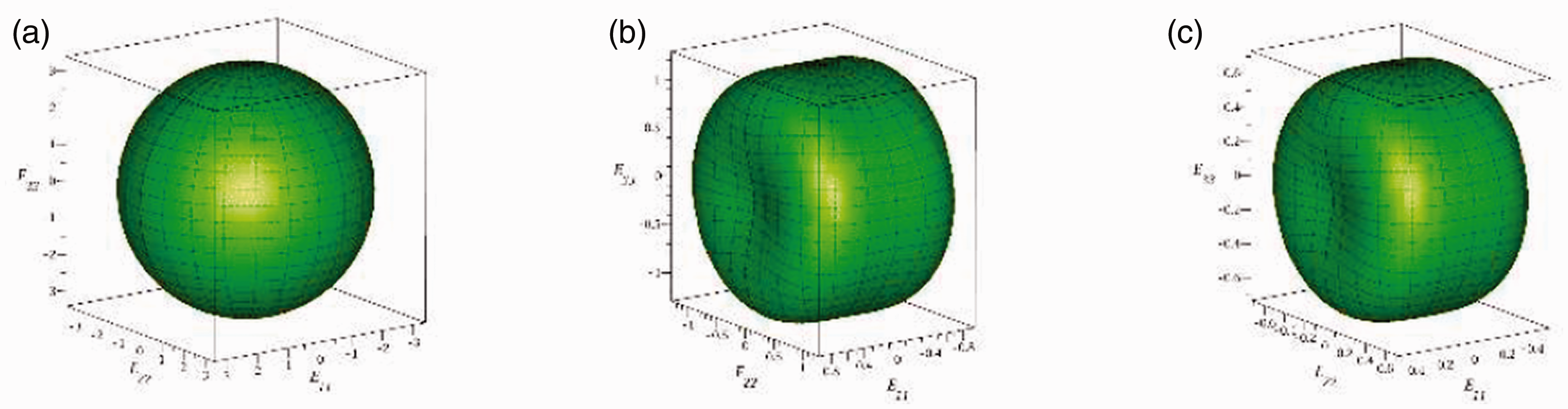
Evolution of an initially isotropic stiffness during multiaxial loading steps, visualized via YMS plots. (a) Strain 0%. (b) Strain 2%. (c) Strain 5%.
Cyclic tensile loading with increasing loading level
We conduct an analysis of the model response upon cyclic loading via uniaxial extension. We successively apply a normal strain
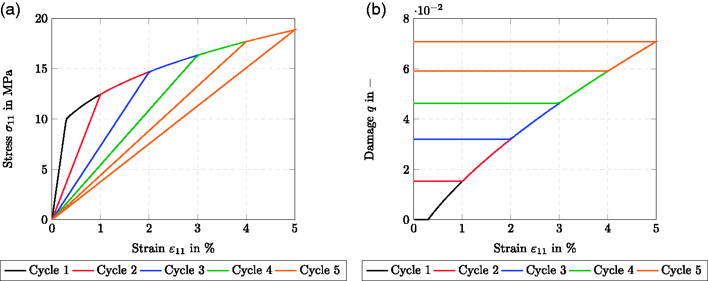
Cyclic tensile loading with increasing loading level for Puck case I. (a) Stress-strain curve. (b) Damage-strain curve.
Upon loading, the material behaves linear elastically until a specific critical stress threshold or the maximum stress of the previous cycle is reached, see Figure 14(a). During the in-between unloading to
Note that the presented model is capable to predict damage onset upon both, tensile and compressive loading. Due to the definition of the damage functions the quadratic nature of the driving force
Model response for a continuous-fiber microstructure
Application of separate loading cases with Puck-type extraction tensors
After discussing the model response for homogeneous stress states, we account for heterogeneous stress states in two ways to show the basic feasibilities of our damage model. First, we shall investigate a microstructure with a continuous fiber reinforcement. In the next section, we will turn our attention to a mesoscale simulation.
To account for damage evolution in the matrix, we introduce two extraction tensor corresponding to the spherical and deviatoric projectors of fourth-order

In three different loading scenarios, we apply three different macroscopic strains via mixed boundary conditions, see Kabel et al. (2016) for details. For each scenario, we analyze the induced damage fields of the associated variables
The average runtime for a resolution of
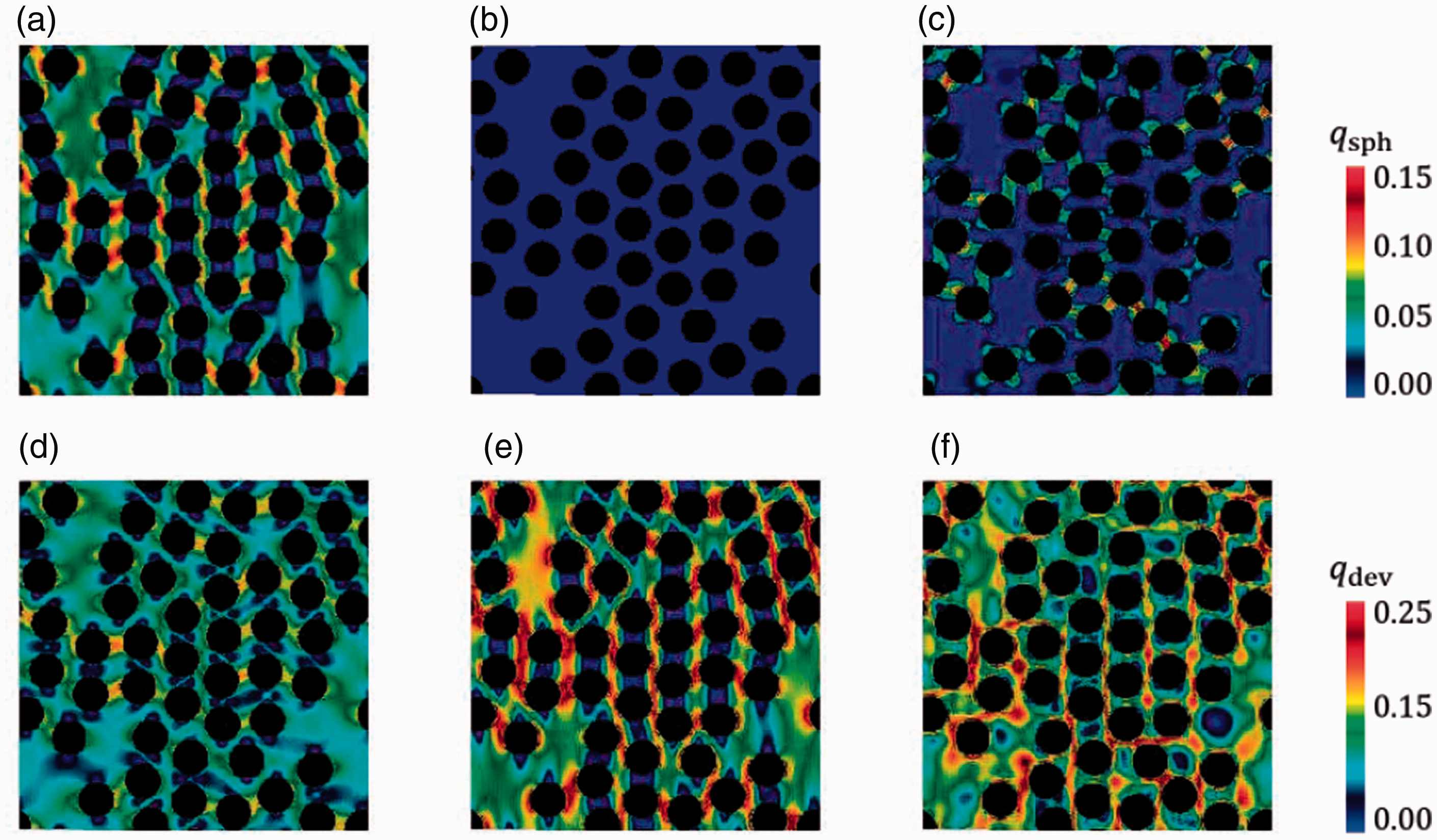
Model response for a continuous-fiber reinforced microstructure based on spherical and deviatoric damage and three different loading cases. (a) Loading
Resolution study
The presented resolution study demonstrates that the proposed damage model leads to mesh-independent results even without gradient enhancement. This does not come by surprise, as we specifically designed such a hardening-type damage model. Still, even in the case of hardening, a resolution study is imperative to ensure mesh-independent results. In particular, we will justify the resolution employed in the previous section.
Figure 16 shows a continuous-fiber reinforced microstructure with the same properties as for Figure 15. We vary the resolution from
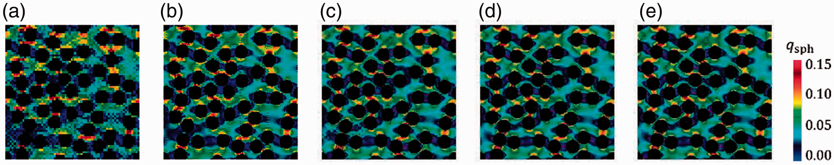
Model response for a continuous-fiber reinforced microstructure evaluated at five different resolutions. (a) 642. (b) 1282. (c) 2562. (d) 5122. (e) 10242.
The resulting distribution of the predominant damage variable
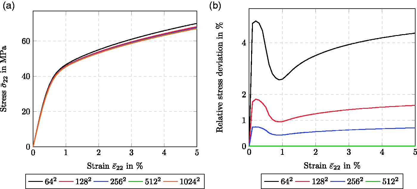
Resolution study for the continuous-fiber reinforced microstructure. (a) Stress-strain curve. (b) Relative stress deviation w. r. t.
Iterations and timings for the conducted resolution study.
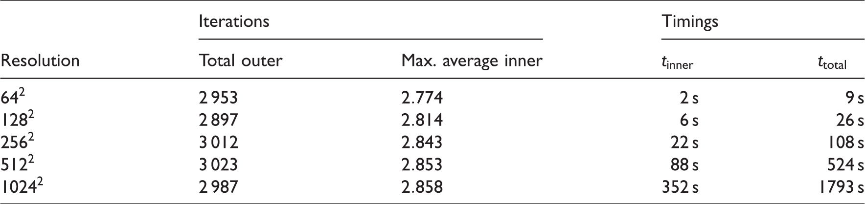
Based on this resolution study, a resolution of
A Plain-weave composite under shear loading
Last but not least, we demonstrate the utility of our model framework for modeling anisotropic damage evolution in a woven fiber-reinforced composite. Simon et al. (2017) investigated the mechanical behavior of a plain-weave composite manufactured from continuous carbon fibers reinforcing an epoxy matrix resin, see Figure 18(a). The carbon fibers are aligned unidirectionally in fiber tows that are regularly interwoven. As each of these tows consists of thousands of carbon fibers, it is customary to work with a multiscale scheme that considers three different scales: the macroscopic scale is large compared to the woven unit cell, see Figure 18(a), which constitutes the mesoscale. Within the latter, the tows are considered homogeneous and anisotropic. On the microscale, the tows get resolved in terms of continuous carbon fibers in an epoxy resin.
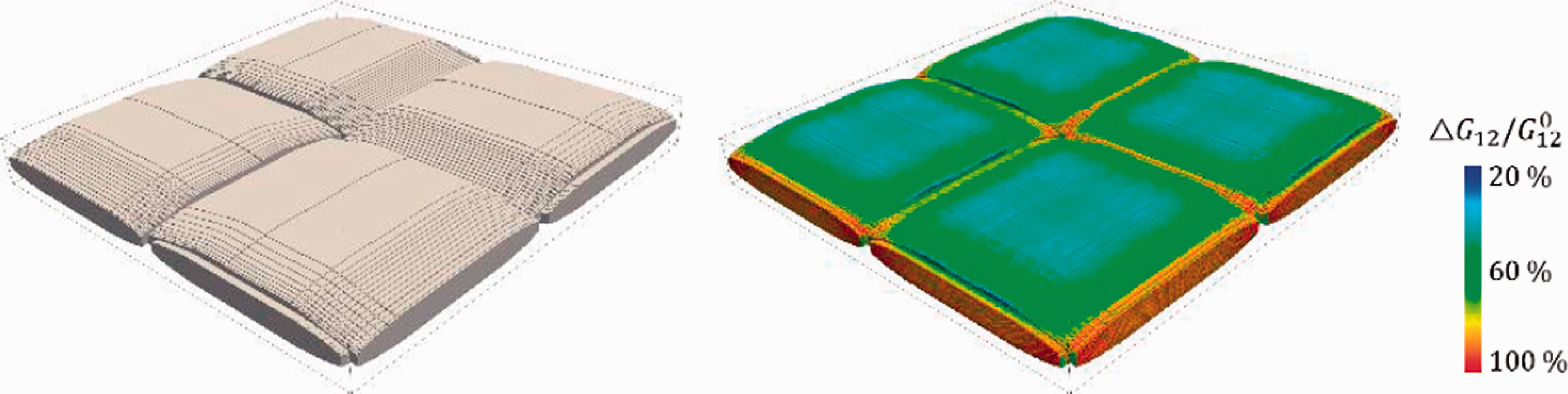
Microstructure and predicted relative reduction of the shear modulus
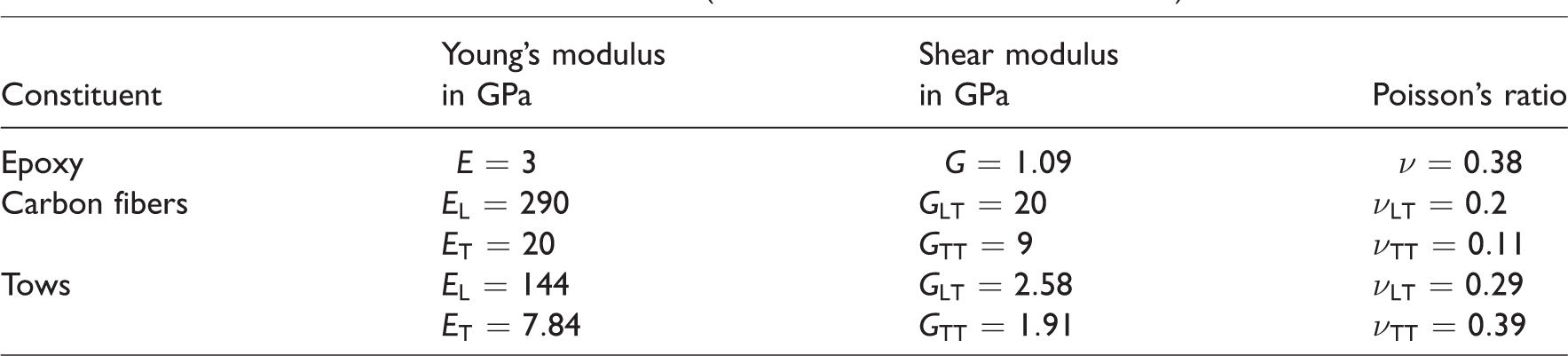
The linear elastic moduli of the considered materials are listed in Table 3. These comprise the isotropic epoxy matrix and the transversely isotropic carbon fibers. The transversely isotropic engineering constants for the tows were obtained by linear elastic homogenization. Please note that the subscript “L” and “T” refer to longitudinal and transverse, respectively.
Elastic moduli of matrix, fibers and tows (Simon et al., 2017, Tables 1 and 2).
Based on earlier work (Bednarcyk et al., 2015, 2014; Stier et al., 2015), Simon et al. (2017) presented a regularized orthotropic continuum damage-model based on the framework developed by Barbero and co-workers (Barbero and Lonetti, 2002; Lonetti et al., 2003, 2004) and concisely summarized in his book (Barbero, 2013). More precisely, their strategy takes the orthotropic engineering constants as the point of departure, and models their degradation on an individual basis in terms of associated scalar damage variables. Based on the associated driving forces, damage surfaces are defined, together with appropriate kinetic laws.
Expressing the dependence of the stiffness tensor on the orthotropic engineering constants is most easily realized in terms of the compliance tensor, the approach of Simon et al. (2017) appears superficially similar to our approach. However, we do not fix the damage variables a priori. Rather, they emerge naturally in our framework based on the chosen extraction tensors and damage-activation functions.
In this paragraph, we demonstrate that our model is capable of reproducing the damage behavior upon quasi-static loading of the weave composite. The protocol we present is straightforward and proceeds step by step. As a first step, we introduce a number of extraction tensors which capture elementary damage cases evoked by pure normal- and shear-loading scenarios. The tensors extract the associated normal and shear stress components from the applied stress state 

Combining suitable damage-activation functions based on these extraction tensors permit modeling a wide range of damage-evolution predictions. In particular, they enable us to describe the stiffness reduction for the scenario considered by Simon et al. (2017).
We first capture the damage evolution in a neat epoxy sample under non-monotonic uniaxial loading and choose an extraction tensor of type (4.5)
Extraction tensors and identified damage parameters to capture the mechanical behavior of epoxy and tow.
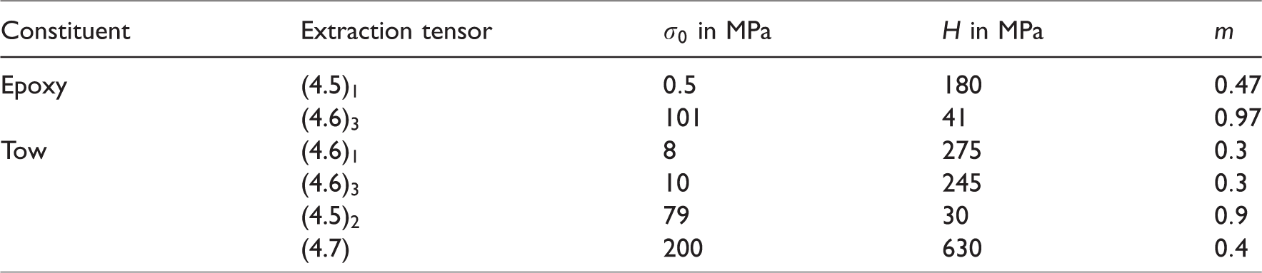
Furthermore, we employ a number of damage-activation functions and suitable extraction tensors to capture the damage evolution in the fiber tows. We fix the longitudinal tow direction to correspond to the local 
With the introduced extraction tensors and damage parameters at hand, we are able to reproduce the experimental results obtained for the neat epoxy resin, as well es the predictions computed by Simon et al. (2017) quite accurately, see Figure 19(a). The decrease in the individual orthotropic engineering-constants are shown in Figure 19(b) to (d), where dashed lines correspond to our model and solid lines refer to the references Simon et al. (2017) and Bednarcyk et al. (2015). For all considered loading cases, our proposed modeling framework makes it simple to account for those engineering constants which remain unaffected during the loading. Figure 19(b) shows that the reduction of Young’s modulus 
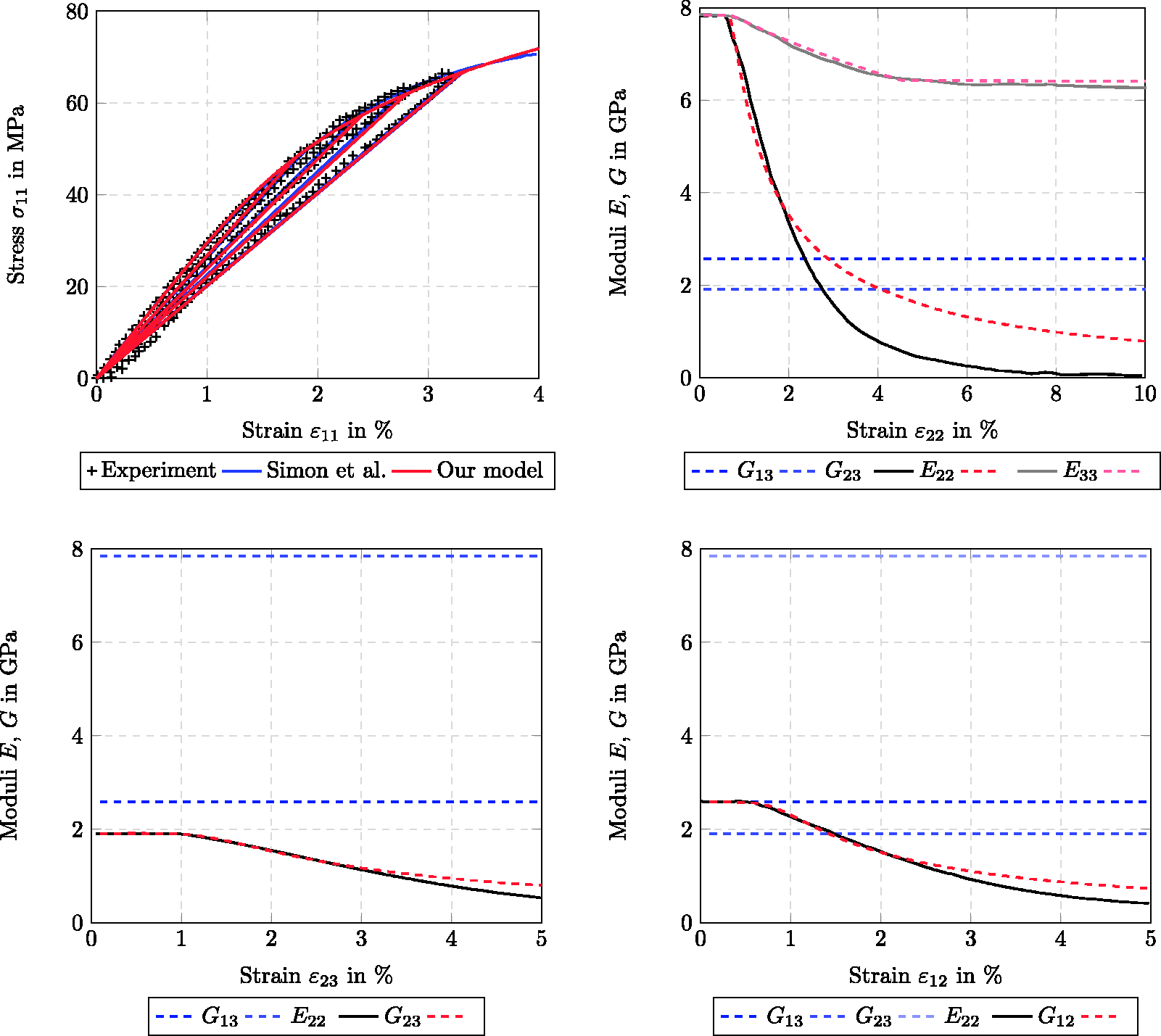
Comparison of predicted stress-strain curve and reductions of the orthotropic engineering constants based on introduced extraction tensors (see Table 4). Our model predictions are dashed in (b)–(d). (a) Neat epoxy behavior under normal loading. (b) Tow behavior under transverse normal loading. (c) Tow behavior under transverse shear loading. (d) Tow behavior under longitudinal shear loading.
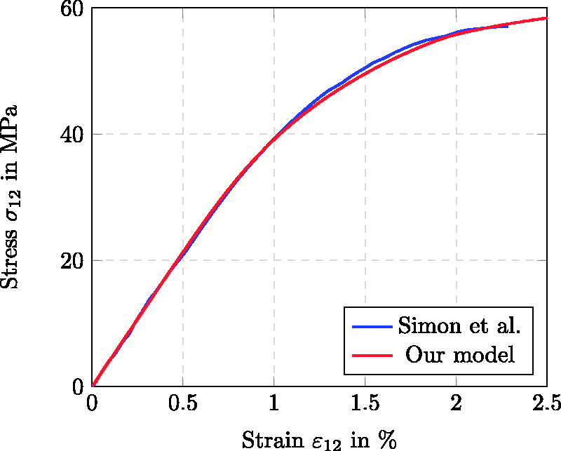
Comparison of effective stress-strain curves for plain weave under shear loading.
Summary and conclusions
In this article, a generalized standard material (GSM) model for anisotropic damage evolution based on the compliance tensor as the primary damage variable was developed. Based on the insight that the Hookean elastic energy density, considered as a function of the elastic strain and the compliance tensor, is a convex function of both arguments, a convex framework for quasi-static damage evolution was established, preventing damage localization intrinsically. Indeed, by choosing the energy (density) related to the progressive degradation of the material appropriately, the condensed incremental potential (Miehe, 2002) is strictly convex and of superlinear growth, which prevents localization for such a model. Of course, working with a softening-type energy for the damage-surface variables is also possible, and should be studied more closely in subsequent work.
The second section is organized to emphasize the modular fashion that the compliance-based damage model is built up. The model might be extended in subsequent work, for instance accounting for strain-rate sensitivity within the model. For an overview of the assumptions leading to specific specializations of the evolution of internal variables, we refer to the overview in Appendix A. The modeling framework is general enough to incorporate coupling to other inelastic models, such as plasticity or viscoplasticity (McDowell, 2008; Rousselier, 1979), entirely within the proposed framework. Also, due to its inherent stability, an extension to fatigue damage, as observed for certain fiber-reinforced polymers (Bartkowiak et al., 2019, 2020; Sauer and Richardson, 1980), appears promising (Magino et al., 2021).
The modular character of the model was exemplified by specific damage-extraction tensors motivated by Puck’s anisotropic failure criteria (Knops, 2008; Puck and Schürmann, 2002). With these ingredients at hand, we demonstrated the model’s capabilities of developing complex anisotropic stiffness states, not restricted a priori by a specific degree of (an)isotropy of the stiffness tensor, emphasizing that the model is capable of handling any initial stiffness. We also showed the model’s capabilities on meso and volume-element scale, based upon a straightforward numerical treatment. With these achievements at hand, accounting for additional failure criteria (Bouhala et al., 2013; Fritzsche et al., 2008; Kaddour et al., 2004) or coupling the model to phase-field fracture models (Gerasimov and De Lorenzis, 2019; Miehe et al., 2010; Schneider et al., 2016a) appears possible.
Returning to our original motivation, i.e., modeling anisotropic damage of SMC composite materials, requires incorporating the presented modeling framework into a three-scale homogenization scheme (Anagnostou et al., 2018). The underlying fiber bundle mesostructure (Dumont et al., 2007; Meyer et al., 2020; Schöttl et al., 2019) has to be accounted for, and the model parameters have to be fitted to experimental data. For the latter purpose, a convenient experimental program is necessary (Schemmann et al., 2018c).
From a mathematical perspective, a thorough mathematical analysis of our model is desirable, whereas an extension to tension-compression asymmetry appears imperative in order to model load reversals.
Footnotes
Declaration of conflicting interests
The authors declared no potential conflicts of interest with respect to the research, authorship, and/or publication of this article.
Funding
The authors disclosed receipt of the following financial support for the research, authorship, and/or publication of this article: JG, MS and TB acknowledge financial support by the German Research Foundation (DFG) within the International Research Training Group “Integrated engineering of continuous-discontinuous long fiber reinforced polymer structures” (GRK 2078).
Acknowledgements
The support by the German Research Foundation (DFG) is gratefully acknowledged. We thank D. Wicht for preparing the plain-weave geometry and S. Gajek for fruitful discussions. We are grateful to the anonymous reviewers for their suggestions and their constructive feedback.
Authorship contribution statement
JG, MS and TB were responsible for the development of the model and methodology presented in this publication. Conceptualization was taken over by MS, AH and TB. The software implementation was done by JG and MS. Validation, investigation of the results, formal analysis and the subsequent visualization were performed by JG. Resources were provided by MS and TB. The original manuscript draft was written by JG and MS and extensively reviewed and edited by JG, MS, AH and TB. The research project was administrated by JG, MS and TB. Funding was acquired by MS and TB. The research was supervised by MS, AH and TB.