
Abstract
This article presents a novel camber-twist morphing flap concept with two chordwise degrees-of-freedom. The flap is capable of reflexed airfoil morphing, thereby decoupling lift from the aerodynamic moment with respect to the aerodynamic centre. The theoretical potential of such a flap is calculated via XFOIL for arbitrary trailing edge shapes, revealing ellipse-like clusters in the lift-moment plane for each value of angle of attack. A conceptual design is proposed, capable of the above functionality. Key features include two spanwise slits along the pressure side skin joined by a flexible structure, with a spar placed between them and two pairs of linear electric motors. The design is validated numerically using a nonlinear aeroelastic analysis toolchain, iterating between the finite element model of the flap and XFOIL. The attainable range of lift-moment combinations is calculated, forming an ellipse-like cluster determined by actuator stroke and force limits. The morphing flap achieves a lift-to-drag ratio of over 104.3 over a range of angles of attack. A high degree of twist morphing range is demonstrated by fixing one pair of actuators and varying the strokes on the other. The range of attainable shapes on the free end is coupled to the fixed end strokes.
Introduction
In recent years, two major factors have driven research and development in aviation: the dangers associated with climate change and the anticipated growth in air traffic (Jensen et al., 2023). Both factors indicate an urgent need for more efficient aircraft. This can be achieved by a combination of higher propulsive efficiency, reduced drag force and reduced aircraft weight, as suggested by the Breguet range equation (Anderson, 2016).
Morphing wings have the potential to yield increased flight efficiency in the latter two ways. One of the many definitions offered in literature describe them as “wings that change shape in flight in a controlled manner to improve aircraft performance” (Vasista et al., 2012). The same authors highlight the changing mission environment during flight and the need for aircraft to adapt accordingly by means of smooth and continuous shape change. Based on the above, a variety of concepts have been developed, as outlined by numerous review papers (Barbarino et al., 2011; Harvey et al., 2022; Vasista et al., 2012; Weisshaar, 2013). These studies identify several morphing modes, each with their respective strengths and weaknesses. Of particular interest are “camber morphing” and “twist morphing.” Camber morphing improves the lift-to-drag ratio
Such morphing wings first made their appearance on the Wright Flyer, whose flexible wings employed twist morphing for roll control (Weisshaar, 2013). After several decades, camber morphing concepts were revisited in the 1980s by the National Aeronautics and Space Administration (NASA) and the Defence Advanced Research Projects Agency (DARPA) in the quest for manoeuvre and gust load alleviation, as well as delayed aileron reversal (Pendleton et al., 2000; Perry et al., 1995; Powers et al., 1992). In the following decades more projects followed in the United States (Jenett et al., 2017; McGowan et al., 2002; Sanders et al., 2004) as well as Europe (De Gaspari et al., 2014; Schweiger et al., 2002; Wölcken and Papadopoulos, 2016) among others. Some notable recent studies include the following. Starting with small-scale studies, the bio-inspired Fish Bone Active Camber (FishBAC) concept demonstrated increased aerodynamic efficiency relative to a hinged flap wing. Lift-to-drag ratio improvements of over 20% were measured via wind tunnel testing over a range of pre-stall angles of attack (Woods et al., 2014). In a different study, Molinari et al. (2016) integrated morphing ailerons in the wings of a 1.75m-span unmanned aerial vehicle, demonstrating the ability to achieve the target lift and rolling moments during flight. Combined camber and twist morphing was investigated in the Variable Camber Continuous Trailing Edge Flap (VCCTEF) programme, where multiple camber morphing flaps were seamlessly connected with the aim of spanwise aerodynamic load control (Nguyen et al., 2015). The short list of full-scale studies includes the Clean Sky programme, where a full-scale morphing flap corresponding to a 100-seat regional turboprop aircraft was built and tested in static conditions (Pecora, 2021). Finally, the Adaptive Compliant Trailing Edge (ACTE) programme stands out, where a morphing flap was installed in the wings of a Gulfstream III business jet, validating the technology via full-scale flight testing (Kota et al., 2016).
Among the many concepts found in literature, the TRanslation Induced Camber (TRIC) concept by the Delft University of Technology stands out for its simplicity. The key feature behind the TRIC is a spanwise slit running along the pressure side skin. The disconnected skin is allowed to translate with respect to the wingbox, morphing the trailing edge (TE) in the process. The above mechanism allows a lightweight design built of conventional skin materials at a minimal drag penalty. This principle has been leveraged by more concepts in literature (Cavalieri et al., 2024; Keidel et al., 2021; Moulton and Hunsaker, 2021). After its original inception as a twist morphing flap (Vos et al., 2010), the camber morphing functionality was added in the EU FP7 CHANGE project (Werter et al., 2016) and further refined in its latest implementation in the Smart-X project (De Breuker et al., 2022). The Smart-X iteration features a pair of electric motors, one on each spanwise end, joined to the wingbox skin and connected via push rod to the end of the pressure side skin. Symmetric actuation induces camber morphing whereas asymmetric actuation induces twist morphing (Mkhoyan et al., 2022). By placing six morphing flaps along the span of a prototype wing, wind tunnel testing demonstrated the morphing wing’s ability to minimise induced drag (Mkhoyan et al., 2023) and alleviate manoeuvre and gust loads (Wang et al., 2021).
A less explored design approach features multiple chordwise degrees-of-freedom (DoF), with two notable studies performed by Pankonien et al. (2015) and Wu et al. (2017). First, the additional DoF helps induce larger morphing deformations. Second, a synergistic combination of actuators can be used to achieve the conflicting goals of the actuation subsystem. Most importantly, the additional DoF offers greater control over the morphing flap shape. Wind tunnel tests by Wu et al. demonstrated the ability to control the coefficient of aerodynamic moment with respect to the aerodynamic centre C mac independently of the lift coefficient C l (Wu et al., 2017). This is achieved by morphing into reflexed shapes, whose superior aerodynamic performance has been the topic of ongoing research (Harvey et al., 2022). These airfoils are characterised by a change in the sign of the camber line curvature. The resulting change in pressure distribution allows control of C mac .
Reflexed airfoil morphing offers two potential advantages towards aircraft-level drag reduction. The first lies in the ability to morph into a wider selection of airfoil shapes, further minimising the drag coefficient C d on the airfoil-level. The second advantage targets induced drag CD,i during flight. Conventionally, a negative lift L t is exerted by the tail to achieve equilibrium in pitch. In the presence of a negative L t , the wings must exert additional lift to maintain altitude. Since CD,i is proportional to the square of the wing lift coefficient CL,w, the negative L t causes an increase in CD,i. The ability of reflexed airfoils to generate a more positive (nose-up) C mac for given C l reduces the dependence on negative L t to achieve pitch equilibrium. Ultimately, the above mechanism reduces CL,w and by extension trim drag, thereby motivating the adoption of morphing wings capable of reflexed airfoil morphing.
This article presents a novel camber-twist morphing flap concept. The design uses the latest implementation of the TRIC concept as inspiration and extends its functionality to morph into reflexed shapes. The rest of this article is structured as follows. In Section 2, the potential of the novel morphing functionality is explored, in terms of attainable aerodynamic polars. A conceptual design is presented in Section 3 with emphasis on key components. Accordingly, a finite element model (FEM) is constructed in MSC Nastran (MSC Software Corporation, 2019) and presented in Section 4. The FEM is combined with XFOIL (Drela, 1989) to form an iterative nonlinear static aeroelastic analysis toolchain, with the purpose of assessing the proposed concept. The range of the camber and twist morphing functionalities is assessed in Section 5. Finally, Section 6 highlights the main conclusions from this study.
Reflexed airfoil morphing aerodynamics
High shape versatility is a key objective for morphing wing designs. In this concept, this translates to a wide range of attainable C l -C mac combinations. Ultimately, the morphing flap aims to achieve these polars at the lowest C d possible. Prior to developing the conceptual design, the theoretical potential of a morphing flap can be demonstrated by calculating the range of attainable polars. This is achieved by globally sampling the possible TE shapes. Upon concept development, the morphing flap shapes form a subset of the sampled shapes and by definition the attainable polars are enclosed by this theoretical limit.
An airfoil parametrisation method is employed to sample the shapes. Focussing on TE morphing, a method is required which keeps the leading edge (LE) geometry unchanged. Hence, the chosen approach is modelled after the Bezier-PARSEC method (Derksen and Rogalsky, 2010). Specifically, the method splits the airfoil into LE and TE, ultimately requiring two camber lines and two half-thickness lines. Each of the four lines is modelled as a
In the present study, the presence of numerous boundary conditions reduces the total number of variables from 20 to 4. Primarily, the LE geometry is fixed, eliminating the 10 variables related to the 2 LE lines. By extension,
Some examples of airfoils are generated using the above parametrisation and shown in Figure 1, relative to the NACA0012. The constraints pertinent to the 60%-chord position and the TE tip can be seen in the half-thickness line and camber line. The TE tip is displaced forward as a result of enforcing constant suction side skin arclength. The three major morphing shape categories are displayed. First, a “conformal” shape, characterised by the monotonic curvature of the camber line. Conversely, reflexed shapes are characterised by a change in the sign of the curvature, as seen in Figure 1. These shapes are further split into “positively reflexed” and “negatively reflexed.”
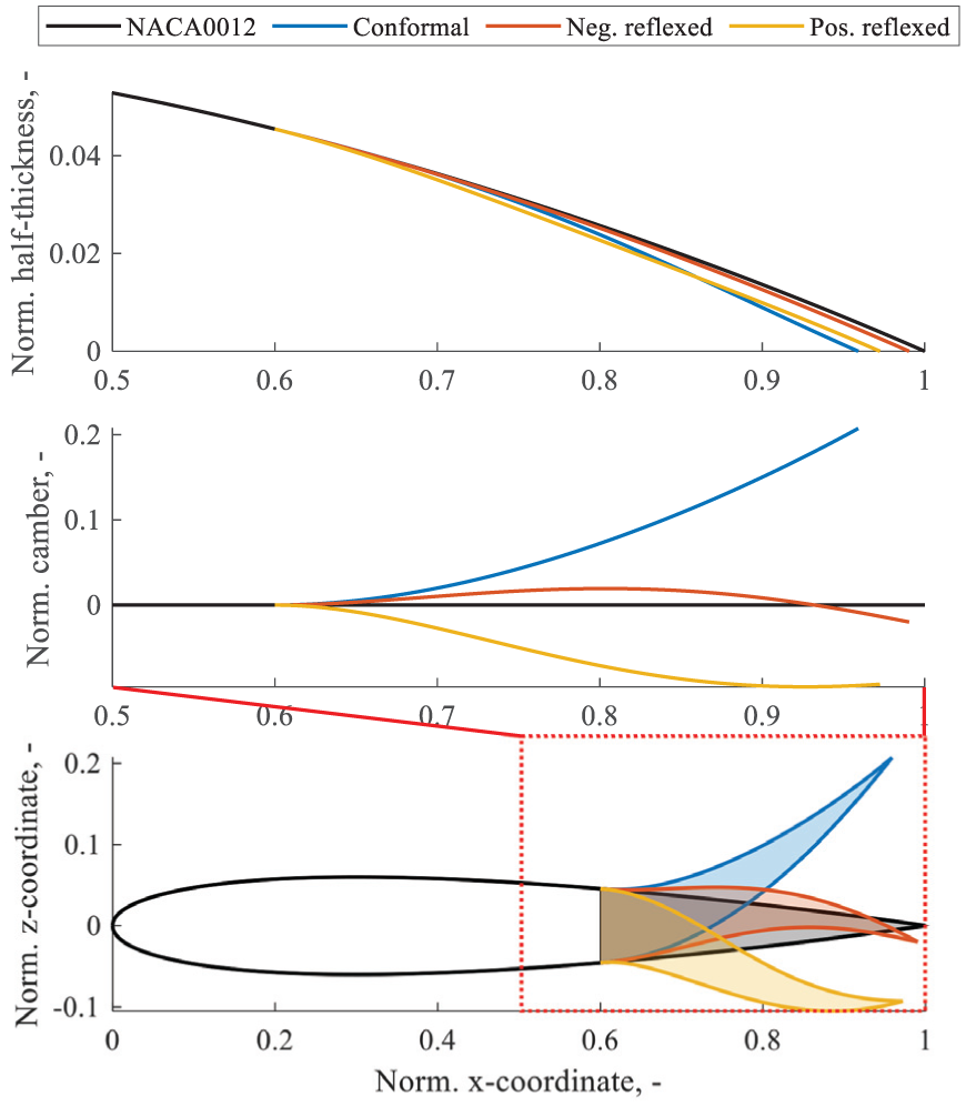
Airfoil geometry parametrisation method. The half-thickness and camber lines are shown for the NACA0012 and three morphed airfoils, with emphasis on the aft half of the airfoil.
With the above parametrisation, airfoil shapes are generated and supplied to XFOIL for two-dimensional (2D) steady viscous aerodynamic analysis. It is noted that the concept is developed in the context of a wind tunnel prototype to be tested in the 2.25m-by-3m Low Speed Tunnel (LST) of the German-Dutch Wind Tunnels (DNW; German-Dutch Wind Tunels, n.d.). This introduces a maximum free stream velocity
For given α, the polars can be plotted in three-dimensional (3D) space, with C
d
on the z-axis for convenience. Given the possibility to obtain airfoils of equal C
l
and C
mac
but different C
d
, the focus lies on the subset of airfoils with minimum C
d
for given C
l
and C
mac
. This subset forms a 2D-surface embedded in 3D-space, as shown in Figure 2 for
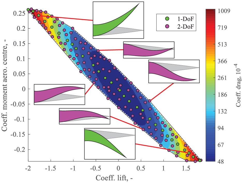
Theoretical limit of C
l
-C
mac
combinations for
The evolution of the clusters over a range of α is presented in Figure 3. For each value of α, the polars exhibit the above behaviour, forming convex clusters. Between
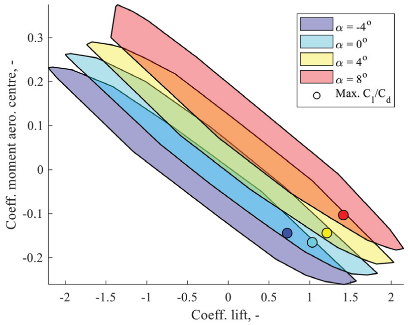
Evolution of clusters of attainable polars over a range of α. For each α value, the airfoil of maximum
The variation of maximum
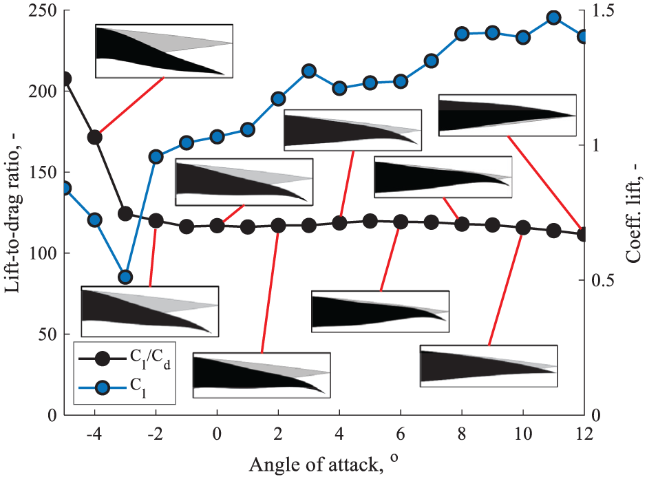
Maximum
Morphing flap conceptual design
The functionality discussed in the previous section serves as a target for the morphing flap. In this section, the conceptual design is presented, with emphasis on individual components. As mentioned in Section 2, the design is developed in the context of a wind tunnel testing campaign, introducing some boundary conditions. The envisioned prototype wing has span length L= 2.25m, chord length c= 0.8m and features three identical morphing flaps of span length l= 0.75m each, with no sweep or taper. The tunnel’s maximum wind speed is
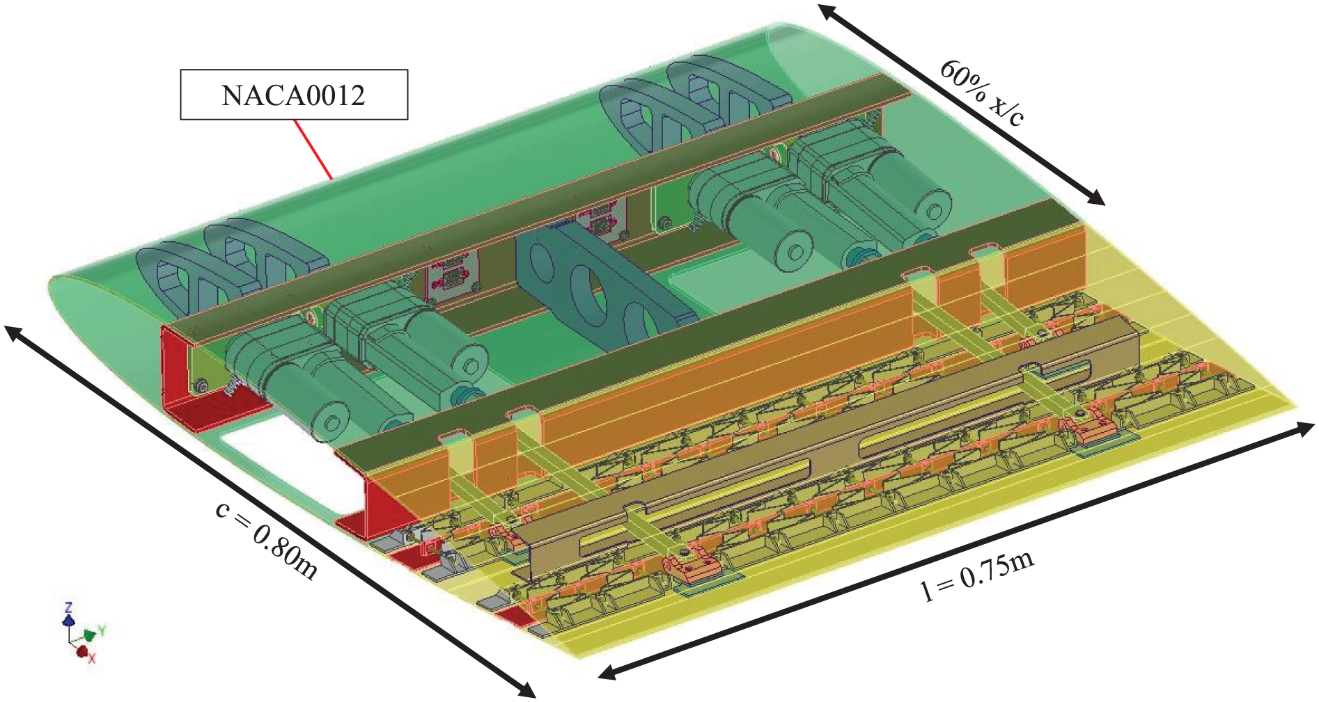
Morphing flap design. Annotations indicate key dimensions and the chordwise onset of the morphing trailing edge.
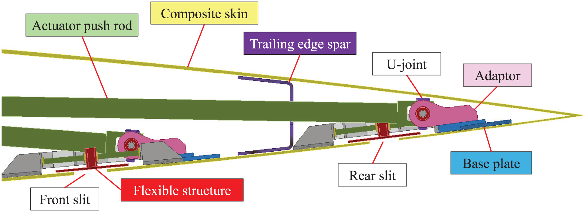
Trailing edge section view on a plane parallel to the x-z plane. Annotations indicate characteristic design features.
As stated in Section 1 of the paper, the latest iteration of the TRIC concept serves as inspiration for this design. Accordingly, the skin is made of a glass fibre-reinforced epoxy laminate, using
With regards to connecting the discontinuous skin, past implementations featured a stiff guide slot, whereby the aft skin was constrained vertically and was allowed to slide in-plane, remaining in contact with the front skin. The above solution is not applicable in the rear slit. The conventional stiff guide slot would greatly limit the range of the twist morphing functionality. Conversely, a flexible guide slot would risk jamming during twist morphing, as a result of slot profile warping. Instead, a flexible skin structure is used, inspired by a past span morphing concept (Bubert et al., 2010), as shown in Figure 7. The structure is characterised by two 3D-printed Nylon-12 components: a “frame” bonded to the skin on either ends of the slit and a “slider” covering the gap left by the slit with its flange and connected to the frame via flexible leaf springs joined to its web, allowing chordwise translation. Bending stiffness is imparted by 3mm diameter steel rods, supported by brass bushings to reduce friction and mitigate the risk of jamming. The rods are placed 60mm apart, overall approximating the glass fibre skin’s stiffness, maintaining curvature continuity. The pattern depicted in Figure 7 is repeated along the span. The leaf springs are omitted and local gaps are introduced locally in the slider web to prevent interference with push rods.
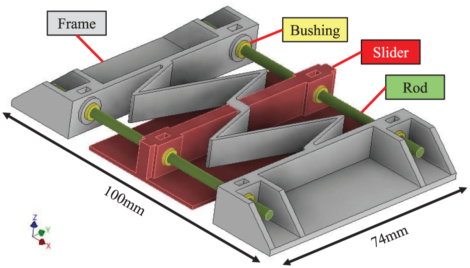
Focused view of flexible skin structure segment. Annotations indicate the dimensions and characteristic design features. The depicted segment is repeated along the y-axis, covering the spanwise length of the pressure side skin.
The actuation requirements reflect the desired functionality. The above paragraphs highlighted the importance of two slits for 2-DoF morphing. Hence, a pair of actuators is needed along the chord, with one actuator joined to the aft end of each slit. Two such pairs are needed, placed symmetrically on each spanwise end of the flap, to impart the twist morphing functionality. Ultimately, symmetric actuation between the two pairs leads to camber morphing. Conversely, asymmetric actuation induces twist morphing. The present choice of actuators was driven by stroke, blocked force, simplicity, compactness and cost, opting for commercially available, linear electric motors. All viable options were too large to fit in the TE, hence the motors are located in the wingbox. The front end of the actuators is attached to the front spar web. Actuation force is then transmitted to the pressure side skin via push rods. This amounts to a parallel connection, which is beneficial for conformal morphing shapes, as the front and rear motor apply forces in the same direction. The contrary is true for reflexed morphing shapes, which are associated with opposing chordwise translation at the slits. To achieve these shapes, the front and rear motor must oppose each other, thereby requiring high actuation forces. Using the developed analysis tool and insight from commercially available options, the DSZY1-24-40-050-POT-IP65 is selected as it meets the above criteria whilst providing 1kN blocked force and 50mm stroke (MSW Motion Control GmbH, n.d.), which are considered sufficient. This choice drives the actuators’ spanwise positioning. In the interest of achieving a high degree of twist morphing, the actuators are placed towards the spanwise ends of the flap. However, adaptor plates are needed to connect to the front spar web. The plate width extends beyond the width of the actuator housing, to allow tool access to bolts in the corners for assembly. As a result, the two front actuators are displaced towards the interior, to the 13.33%-span and the 86.67%-span position. Equivalently, the two rear actuators are placed further inwards at the 22.67%-span and 77.33%-span position.
The actuators are connected to the structure on both ends via universal-joints, which allow rotations along the y-axis, associated with camber morphing, as well as the z-axis, associated with twist morphing. In the front end a universal-joint connects the motor housing to an adaptor plate, which is fixed on the front spar web. Similarly, a universal-joint connects the push rod end to an adaptor plate, which is fixed to a base plate. The base plate is bonded to the skin, thereby transmitting actuator force to the pressure side skin. Ultimately, this corresponds to an open-loop linkage, such that the morphing flap will be subject to aeroelastic deformations. These deflections are limited to an acceptable magnitude by tailoring the skin stiffness accordingly.
Finally, a TE spar is included between the two slits. This component is crucial to achieve reflexed airfoil morphing. The underlying principle is demonstrated schematically in Figure 8, for the case of positively reflexed morphing, which requires chordwise contraction at the front slit and expansion at the rear slit. The spar splits the TE in two parts. In the front, displacement due to contraction is translated to a force f front exerted by the pressure side skin on the web. This force generates a clockwise moment on the suction side skin, causing the skin to bend in the direction of the negative z-axis. Conversely, in the rear, displacement due to expansion is translated to a force f rear exerted by the pressure side skin on the suction side skin. This force generates an anti-clockwise moment on the suction side skin, causing the skin to bend in the direction of the positive z-axis. Combined, these effects cause the change in curvature sign, associated with reflexed airfoils. To achieve this it is crucial to tune the spar stiffness appropriately. Excessive stiffness increases the required actuation forces. Conversely, excessive flexibility deforms the web, reducing the magnitude of the exerted moments. Hence, 1.5mm thickness steel sheet was found to strike that balance. The spar web also features two slender gaps, allowing access to push rods and reducing its torsional stiffness, thereby promoting twist morphing. However, a web is included between the gaps connecting the two skins in the middle of the flap, thereby mitigating skin deflection due to suction resulting from lower pressure in the exterior.
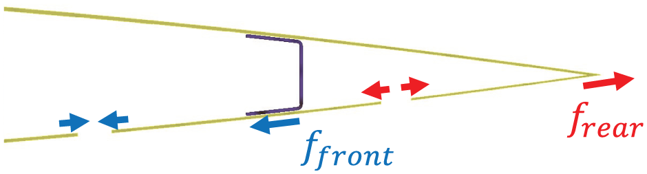
Schematic representation of the principle behind reflexed airfoil morphing. Chordwise translation at the slits induces forces in opposite directions. The trailing edge spar transmits moments between the two skins, resulting in the corresponding skin curvature.
Numerical analysis toolchain
In Section 3 a conceptual design is proposed with the aim of achieving the desired morphing functionality. A set of components and features are therefore selected, each contributing to the above objective. In Section 5 numerical analysis results are used to assess the concept’s functionality. This section presents the numerical analysis toolchain developed for that purpose. The analysis revolves around the FEM of the morphing flap structure, modelled in MSC Nastran. The FEM is shown in Figure 9, including annotations indicating the elements corresponding to the key components. Visual access to the flap interior mesh is obtained by removing some suction skin elements.
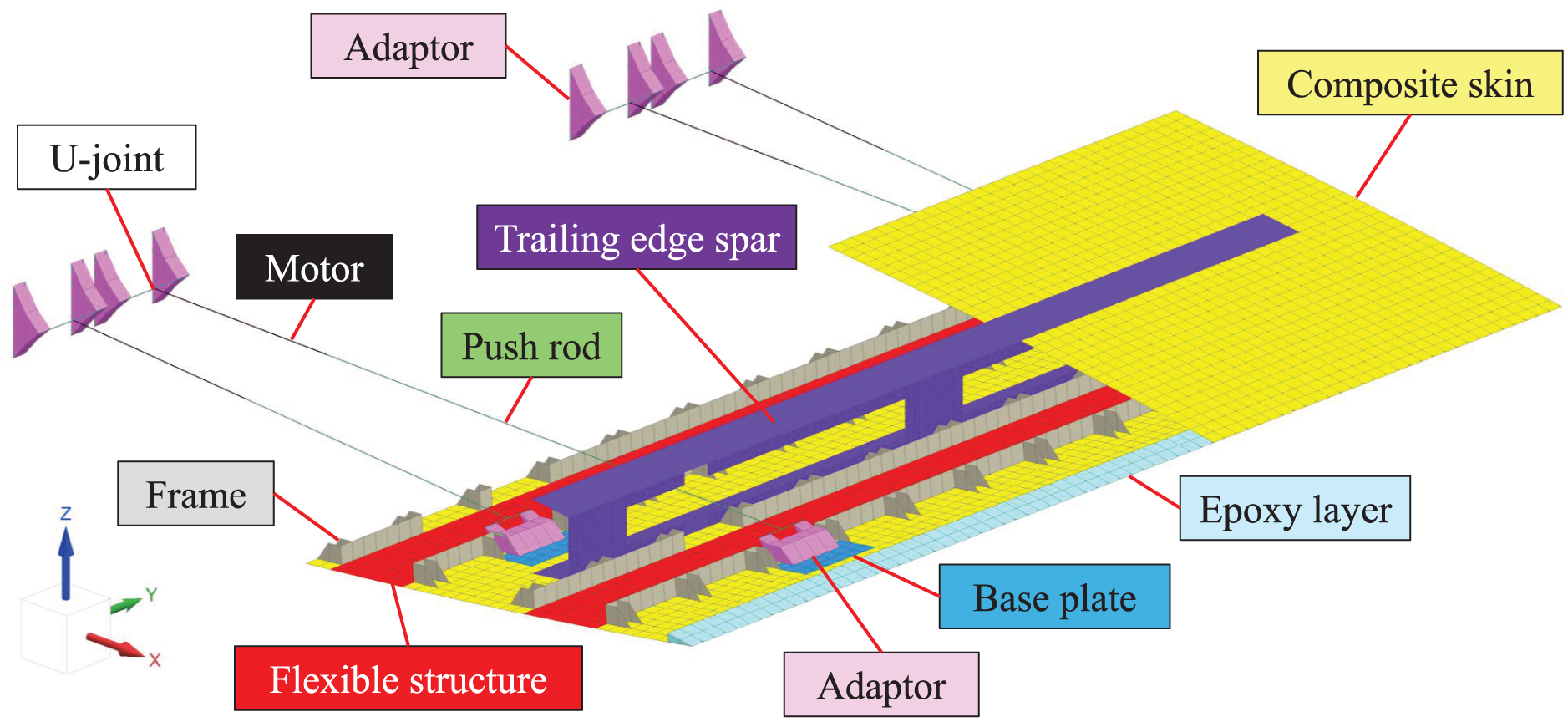
Morphing flap finite element model. Part of the suction side skin mesh is omitted for demonstration purposes, providing visual access to the interior. Annotations indicate the mesh corresponding to key components.
In total, the FEM is made of 5801 elements. An average element edge length of approximately 10mm is maintained across the mesh. Shell elements (CTRIA3, CQUAD4) approximate thin-walled structures like the composite skin, trailing edge spar and 3D-printed frame. Such elements are also used to model the base plate and the TE spar flange. These low thickness components are in contact with the skin and are therefore merged into single shell elements, with layered composite properties (PCOMP). Solid elements (CPENTA6, CHEXA8) are used to model the adaptors used to connect the actuators on either end. These components are significantly stiffer than the surrounding structure, justifying the use of a coarse mesh. Solid elements are also used to model the thick layer of epoxy used to join the two skins along the TE tip.
Beam elements (CBEAM) are used to model the actuators, treating push rods and motors individually. The push rods are modelled realistically using the correct material properties and beam profiles. The structure of the motor housing remains undeformed during operation. It is therefore approximated as rigid. However, beam elements are preferred over rigid-body elements, as the former can be used to simulate displacement along the motor axis by means of thermal strains. Overall, artificial material properties are used in the elements representing the motors. This includes a Young’s modulus of
Rigid-body elements are used to connect the actuators to the adaptors. First, RBE2 elements are defined between the arms of the adaptors, with a node at the point of connection. The universal-joints are simulated via RJOINT elements between these nodes and the actuator end nodes. Finally, for the purpose of the analysis, the LE is approximated as quasi-rigid. It is therefore represented via clamped boundary conditions on the skin nodes in the front end of the TE as well as the front adaptor nodes in contact with the front spar.
Overall, the mesh of the FEM is constructed with emphasis on the composite skin, which exhibits significant deformation during morphing. Specifically, for each of the two skins, a 32-by-75 element mesh is used to model the 320mm-by-750mm flap skin. This amounts to a total of 4800 CQUAD4 elements of aspect ratio 1, forming the majority of the elements. The above follows the approach adopted by Mkhoyan et al. (2022) in a past study regarding the development of a camber-twist morphing flap, featuring glass fibre skin of dimensions 200mm-by-300mm. Specifically, they report mesh convergence at a mesh seed size of 10mm. The present study maintains these element dimensions in the context of a larger structure, thereby further refining the mesh.
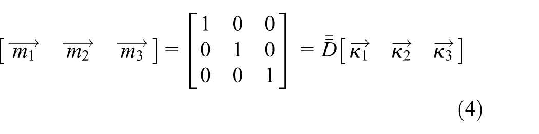
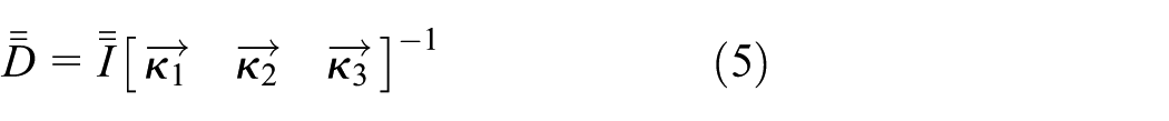
An alternative modelling approach is taken for the flexible skin structure. The approach aims to capture the structure’s stiffness properties whilst limiting element count and avoiding rod-bushing contact modelling, thereby reducing computational cost and improving computational stability. Hence, the structure is approximated as a shell with anisotropic membrane and bending stiffness. The above resembles a laminate, hence its constitutive equation is given from classical laminated plate theory (Kassapoglou, 2013). The stiffness matrix is made of two symmetric matrices: the membrane stiffness
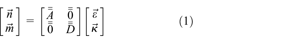
Calculating
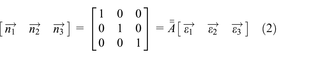
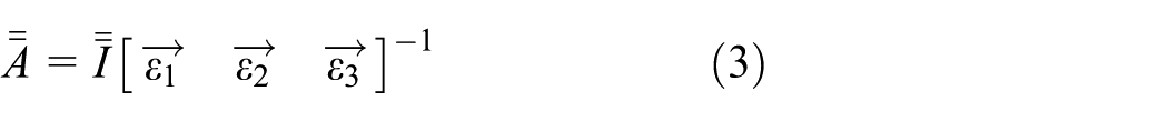
A schematic representation of the auxiliary FEM is shown in Figure 10; the depicted pattern is repeated to yield uniform deformation, avoiding boundary effects at the edges. The two stiffness matrices are primarily influenced by the presence of the steel rods. The leaf springs are included to capture chordwise in-plane stiffness. The slider mainly affects spanwise in-plane stiffness and is modelled without the flange for simplicity. The leaf springs and slider beams are modelled with shell elements. The steel rods resist transverse bending whilst allowing axial translation and rotation. To simulate these mechanics, they are treated as Euler-Bernoulli beams. Therefore, their stiffness matrix is calculated analytically and directly added to the corresponding nodes as direct matrix input (DMIG). Finally, an auxiliary membrane is added, covering the mid-plane of the structure normal to the out-of-plane axis. Its material is defined with artificially low stiffness, to ensure it does not affect the structure’s overall mechanics. Its purpose is to provide a reference surface to calculate strain and curvature. Static stability is achieved via clamped boundary conditions at a node in the centre of the membrane mesh. A set of unit
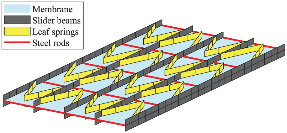
Schematic representation of finite element model of the flexible skin structure. An auxiliary membrane serves as a reference surface for strain and curvature calculation.
Based on the developed FEM, a nonlinear static aeroelastic analysis toolchain is established, iterating between the FEM and XFOIL. The toolchain is presented in the form of a flowchart in Figure 11. To initiate the loop, the four actuator strokes
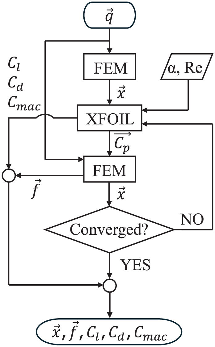
Numerical analysis flowchart. The tool iterates between nonlinear static finite element analysis and 2D steady viscous aerodynamic analysis.
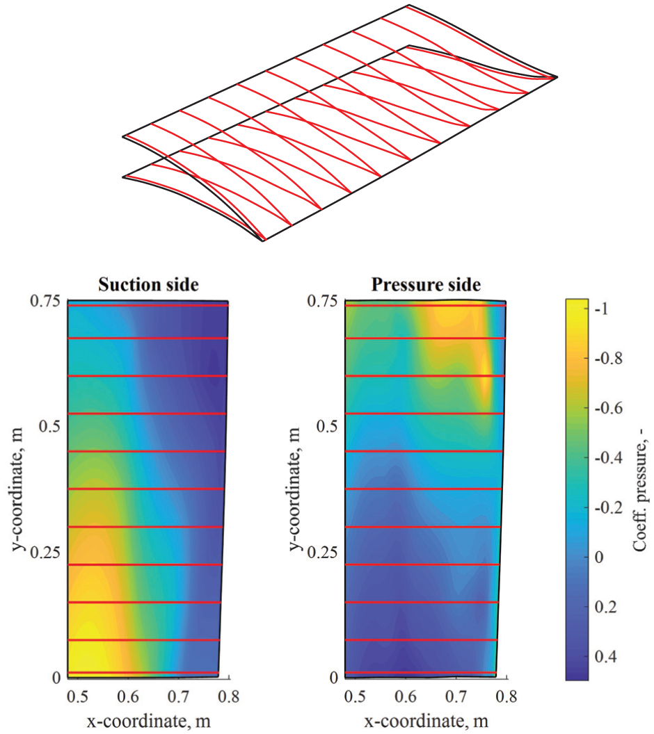
Numerical analysis results. A morphing trailing edge is presented in terms of shapes projected on planes parallel to the x-z plane. Contour plots projected on the respective flap skins represent the interpolated pressure distribution. Red lines indicate the spanwise position of the projected airfoils.
Two distinctions are made regarding the aerodynamic analysis. First, in the presence of asymmetric morphing, the analysis fails to capture the influence of crossflow. Crossflow affects primarily boundary layer flow, hence C
d
results are omitted. However, given the attainable degree of twist morphing, the influence of crossflow on
Morphing flap functionality assessment
The performance of the proposed morphing flap concept is assessed numerically. All XFOIL runs were performed with the maximum Re and q attainable by the envisioned wind tunnel, as defined in Section 2.
The range of the camber morphing functionality is shown in Figure 13, in terms of attainable C
l
-C
mac
combinations for
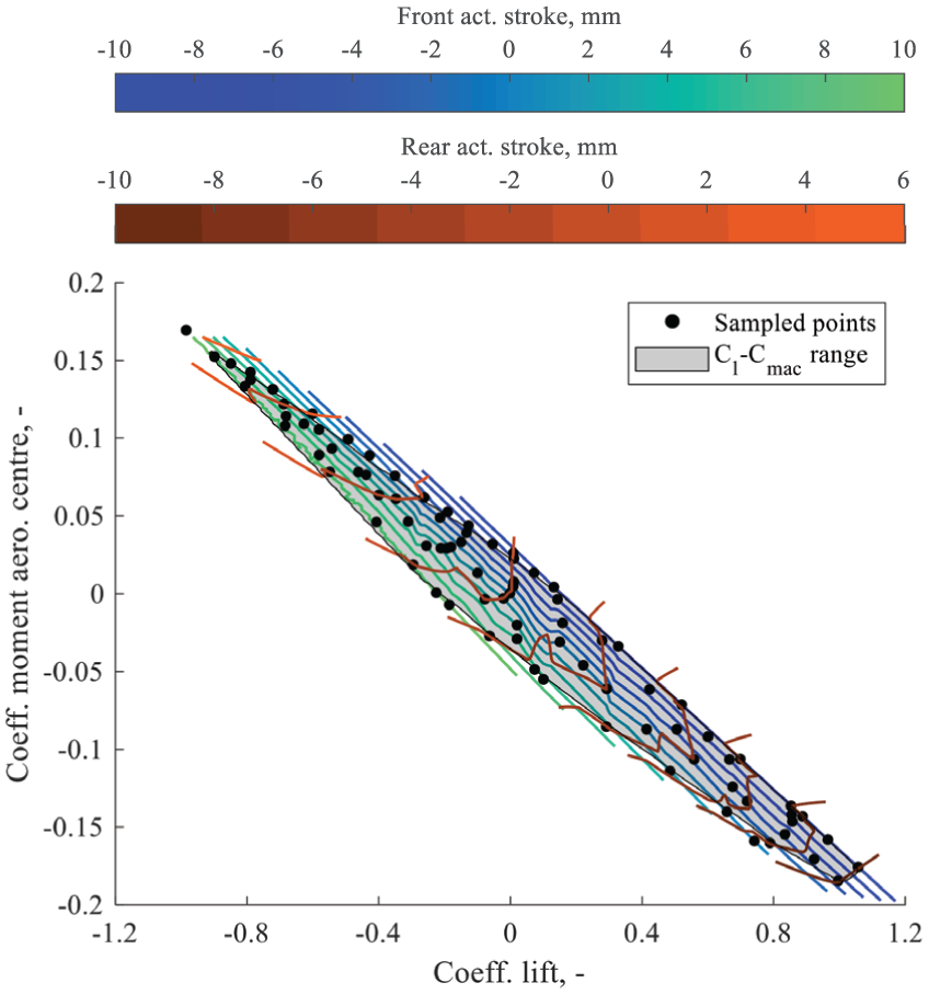
Camber morphing range defined as a cluster in the C
l
-C
mac
plane for
The isolines indicate the actuator stroke settings required to achieve a given C l -C mac combination. The values on the colorbars correspond to the depicted stroke levels. It is noted that the rear actuator stroke q rear is limited to a maximum of under 6mm due to excessive actuator force requirements. The isoline spacing is kept constant at 2mm stroke, thereby revealing the polars’ sensitivity to each actuator. For given front actuator stroke q front , a step increase in q rear causes a large change in the general direction of the cluster’s major axis, resembling 1-DoF morphing. Graphically, this corresponds to selecting one of the blue-green isolines and spanning its length in the direction of negative C l . Conversely, for given q rear , a step increase in q front causes a small change in the general direction of the cluster’s minor axis. Graphically, this corresponds to choosing one of the brown-orange isolines and spanning its length in the direction of negative C mac . From minimum to maximum q front , the airfoil evolves from a positively to a negatively reflexed shape.
As discussed in Section 3, the choice of an open-loop linkage in conjunction with a flexible skin introduces aeroelastic deflections. Their effect on the camber morphing functionality is presented in Figure 14 for
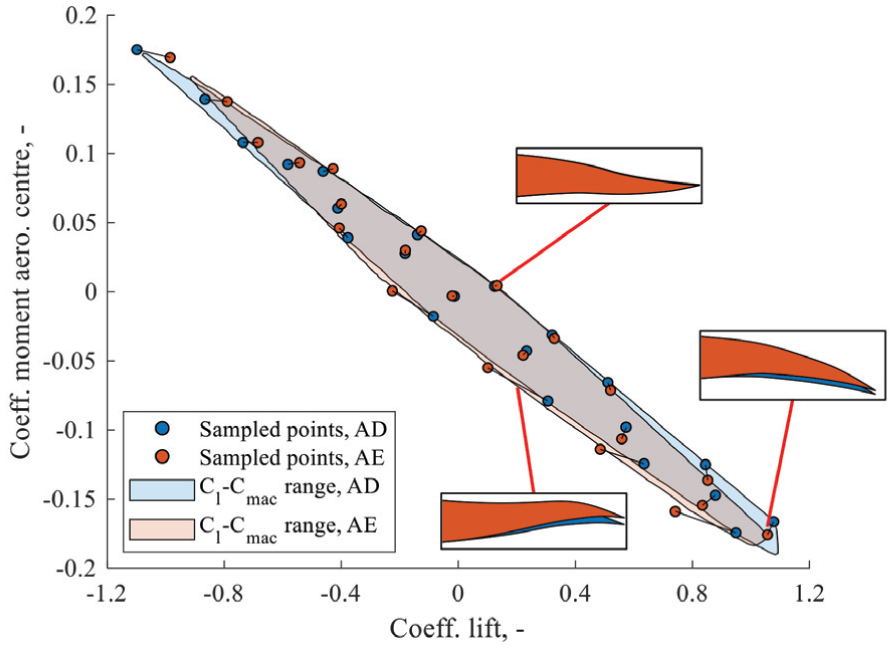
Influence of aeroelastic deflections on the morphing functionality for
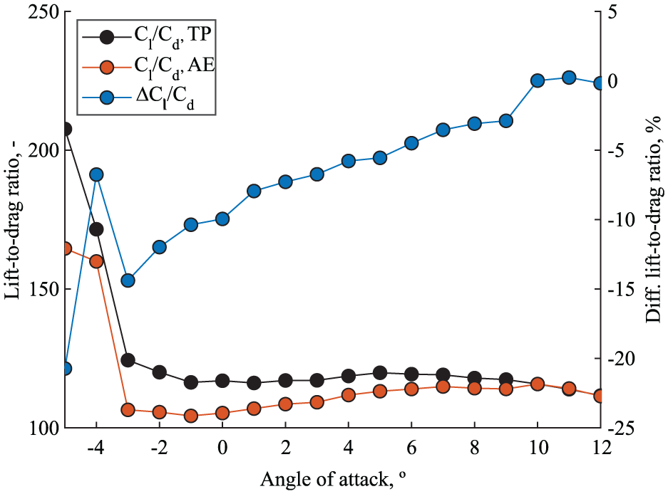
In the absence of structural constraints, the ideal morphing flap would reach the theoretical potential presented in Section 2. The developed concept is therefore assessed relative to that potential; this dataset is labelled “theoretical potential” (TP). In Figure 15 the range of C
l
-C
mac
combinations attainable by the flap is plotted along with the theoretical boundary for
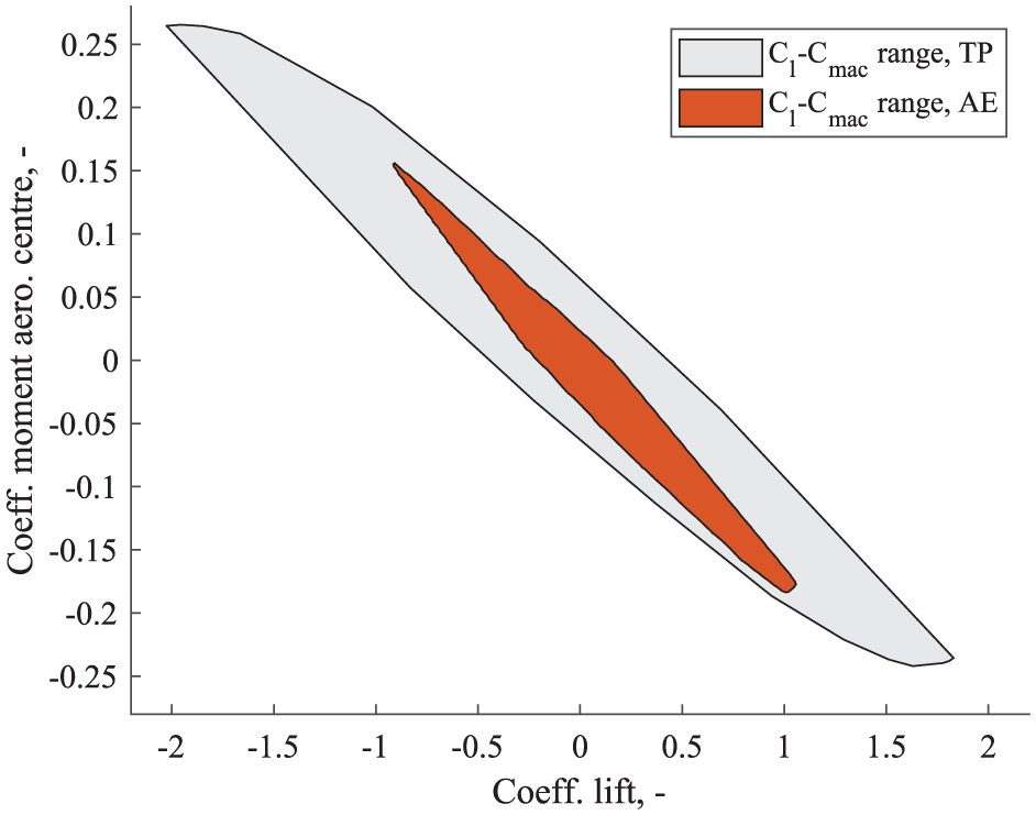
Attainable camber morphing range relative to the theoretical limit at
Regarding aerodynamic efficiency, the maximum
Attainable
Finally, the range of the twist morphing functionality is shown in Figure 17, for
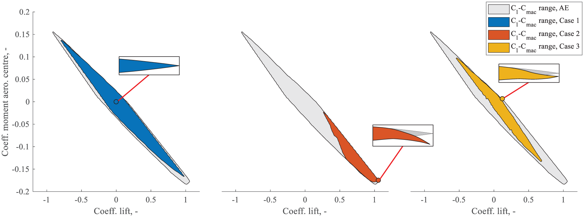
Twist morphing range expressed in terms of the range of shapes attainable by the free end of the flap, for given actuator strokes on the fixed end, for
Conclusion
The central motivation of this paper was to present a novel camber-twist morphing flap concept. Using the TRIC concept as inspiration, a flap design was obtained capable of morphing into reflexed airfoil shapes, whilst maintaining the twist morphing functionality.
The reflexed airfoil morphing functionality was first explored in terms of an arbitrary morphing flap’s ability to obtain a wide range of C
l
-C
mac
combinations and maximise
The following notable design features combine to achieve the desired morphing functionality. Two spanwise slits combine to yield conformal as well as reflexed airfoil morphing. The discontinuous skin was joined by a flexible structure capable of chordwise translation by means of chordwise leaf springs and steel rods. A TE spar was introduced between the two slits, capable of transmitting the moments necessary to morph into reflexed shapes. A total of four linear electric motors were included, necessary to combine the reflexed airfoil with the twist morphing functionality. Universal joints were used to connect the actuators to the structure resulting in an open-loop linkage which does not prevent aeroelastic deflections. The flap design was translated to a FEM and a nonlinear static aeroelastic analysis toolchain was established as a loop between FEM and XFOIL.
The attainable range of C l -C mac was calculated, as determined by actuator stroke and force limits. The boundaries form an ellipse-like cluster validating the concept’s ability to decouple C mac from C l . Isolines representing stroke levels revealed the polars’ sensitivity to the respective actuators. Comparing results before and after aeroelastic deflections, the magnitude of deflection, and hence change in polars, was found to depend on the pressure distribution, as dictated by the airfoil shape. Negatively reflexed shapes deflected the most, whereas positively reflexed shapes were marginally affected. The AE cluster area was reduced by only 3.74% relative to the AD cluster, validating the morphing functionality in the presence of aeroelastic deflections.
Compared to its theoretical potential, the AE cluster was reduced by 77.47%. At
When varying stroke settings on the free end, the range of twist morphing functionality was found to depend on the actuator strokes on the fixed end of the flap. The Case 1 cluster covers 75.2% of the camber morphing range, including all types of shapes. The Case 2 cluster covers 26.8% of that range, limited to high C l shapes with emphasis on positively reflexed shapes. The Case 3 cluster covers 38.9% of the range, alternating between positively reflexed shapes in the negative C l range and negatively reflexed shapes in the positive C l range.
Footnotes
Acknowledgements
The authors acknowledge the partnering organisations from the RICHTING project: Dutch-German Wind Tunnels (DNW), Royal Netherlands Aerospace Laboratory (NLR), Qlayers, Netherlands Organisation for Applied Scientific Research (TNO).
Funding
The authors disclosed receipt of the following financial support for the research, authorship, and/or publication of this article: The authors acknowledge the financial support of the Dutch government through the Netherlands Enterprise Agency (RVO) under the TSH Vliegtuigmaakindustrie programme, project number TSH21009. The RICHTING project (Radicale weerstands en gewICHTsreductie door morphING en microstructuren) started on January 1st 2022 and was concluded successfully on June 30th 2025.
Declaration of conflicting interests
The authors declared no potential conflicts of interest with respect to the research, authorship, and/or publication of this article.
Data availability statement
Data sharing not applicable to this article as no datasets were generated or analysed during the current study.