
Abstract
This work introduces a novel concept of modular, shape-adaptable sandwich panel with a distributed actuation system based on shape memory alloys (SMA). The panel consists of a modular arrangement of rigid cells connected with compliant active joints. Each joint hosts a SMA wire, which can be controlled independently, enabling the panel to achieve multiple shapes and complex curvatures with a single design. A numerical model of the actuators is developed combining the SMA model proposed by Brinson with a finite element model of the compliant joints, and validated against experimental results. Further, a demonstrator of the panel is manufactured and tested implementing four different actuation patterns and measuring the final shapes with a digital image correlation system. The results prove the capability of the proposed concept to achieve both in plane and out-of-plane deformations in the order of millimeters to centimeters, and to reproduce shapes with double curvatures. With the possibility to integrate sensors and additional components inside the core, the proposed shape-adaptable panel can be used to realize smart structures, which might be used for morphing aerodynamic surfaces or reconfigurable space structures.
1. Introduction
Adaptive structures are capable of modifying their properties in order to improve performance and efficiency over a large spectrum of working conditions (Murata et al., 1998). Shape-adaptable aircrafts or terrestrial vehicles can optimize the airflow around their bodies to reduce drag and fuel consumption (Barbarino et al., 2011; Daynes and Weaver, 2013). Adaptive structures based on metamaterials can be used to achieve programmable properties (Bodaghi et al., 2017) or for the control of vibrations (Bergamini et al., 2014). Mechanically reconfigurable antennas can vary the shape of the radiating structure to change operating frequency and radiation pattern, and are particularly suitable for space applications (Christodoulou et al., 2012).
Adaptive structures rely on the integration of active elements capable of varying their properties in order to achieve changes in shape and structural response. Particularly interesting is the development of adaptive sandwich panels because this type of construction is broadly used both in primary and secondary load carrying structures (Zenkert, 1995) performing multiple functions, such as thermal or acoustic insulation (Zenkert, 1995), liquid storage (Vinson, 2001), or energy absorption in case of impact (Alavi Nia et al., 2017). Moreover, sandwich panels can host sensors, actuators, and additional electronic components, whose miniaturization has recently opened the door to a new class of adaptive structures, called smart structures, capable of autonomously change shape and modify static and dynamic response to improve the performance or add new functionalities to a large number of industrial products (Chopra and Sirohi, 2013).
Smart materials are functional materials that can directly convert energy from a non-mechanical to a mechanical domain and represent a very promising solution for the realization of multifunctional components that can perform sensing, control, and actuation (Tzou et al., 2004) and, therefore, of smart structures. Unlike conventional actuators, smart materials are characterized by a monolithic design that is not subject to wear, require no lubrication and can be easily integrated into structures without complex mechanisms and bulky power distribution systems (Tzou et al., 1989). Nonetheless, the integration of smart materials in structures implies an increase in the complexity of the system and introduces issues related to non-linear behaviors, manufacturing, and possibility of inspection and re-pairing (Barbarino et al., 2011).
Shape memory alloys (SMA) are a class of smart materials that can provide high actuation forces and large displacements but at a relatively low frequency (Barbarino et al., 2014). Due to their high energy density, their fatigue life of millions of cycles (McNichols et al., 1981) and the possibility to reduce the complexity of a system by reducing the number of moving parts, SMA actuators present an attractive solution for medical, robotic, as well as aerospace applications (Campanile et al., 2004; Hartl and Lagoudas, 2007; Kheirikhah et al., 2011; Nespoli et al., 2010). Nonetheless, the use of SMA actuators has been limited so far by the non-linear dependency of strain on stress and temperature, and by the consequent difficulty in predicting precisely their response (Hartl and Lagoudas, 2007).
In this paper, we present a novel type of SMA actuator for the realization of smart structures and introduce a numerical routine to model its behavior. Further, we demonstrate that the proposed actuators are suitable for the realization of a distributed actuation system and propose a novel concept of modular shape-adaptable sandwich panel. The design of the panel was inspired by the work of Hwang et al. (2016), who conceived a bendable truss core for the construction of curved sandwich panels made of stiff pyramidal Kagome structures connected through compliant bending zones. In our concept, the compliant bending zones are replaced by the proposed actuators, which act as active joints between different rigid cells. Each joint can be controlled independently through an electric input, allowing for the variation of the distance as well as the orientation of neighboring cells. The result is a smart structure that can assume multiple complex shapes and that might find application in the aerospace or in automotive sector for morphing aerodynamic surfaces or in reconfigurable space structures.
2. Design and working principle
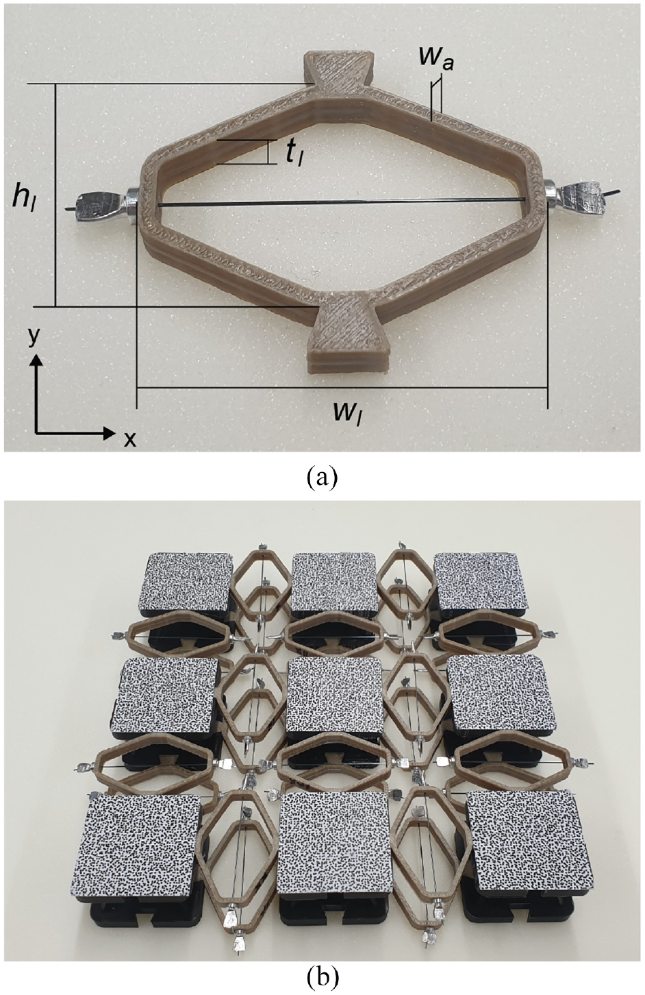
The concept of shape-adaptable sandwich panel presented in this work is depicted in Figure 1(a) and consists of a check pattern of stiff cells connected by compliant active joints. The latter are made of a leaf spring actuated by a pre-strained SMA wire, which ensure can be easily activated through an electric power input (Bil et al., 2013). The panel cells are made of two stiff platelets connected by a pyramidal truss core (George et al., 2013; Li et al., 2011). This construction can achieve outstanding stiffness-to-density and strength-to-density performance (Eichenhofer et al., 2017) while leaving enough room for the integration of the electrical components required to control the structure. The active joints are rigidly connected to neighboring platelets on the upper and on the lower face sheet of the sandwich panel and their compliant design allows for the control of the distance (Figure 1(b)) as well as the angle between neighboring cells (Figure 1(c)). This feature gives the structure the capability of deforming both in-plane and out-of-plane direction and assuming complex shapes with multiple curvatures (Figure 1(d) and (e)).
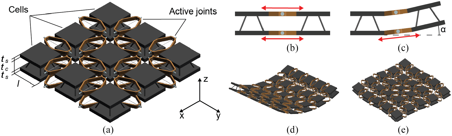
(a) Investigated shape-adaptable sandwich panel concept. Relative position of two neighboring cells (b) when both active joints are actuated and (c) when only the lower joint is actuated. Examples of shapes achievable by the proposed shape-adaptable sandwich panel concept: (d) single curvature and (e) positive and negative curvatures.
The actuation principle of the proposed active joints is depicted in Figure 2 and works as follows: when heated up above the austenite start transformation temperature, the pre-strained SMA wire contracts, deforming the leaf spring, which contracts in the direction of the SMA wire and expands by an amount Δh in the perpendicular direction, pushing the neighboring platelets apart. Like in the “Fish-mouth” actuator (Campanile et al., 2004), the leaf spring performs both the function of displacement-amplification mechanism and that of bias spring. Indeed, the stiffness of the leaf spring is selected in a way that, when the SMA wire cools down after actuation, the elastic recovery of the leaf spring has enough authority over the SMA wire to re-stretch it to its initial state. In this way, it is possible to obtain multiple actuations and a result similar to a two-way shape memory effect with a one-way SMA wire.
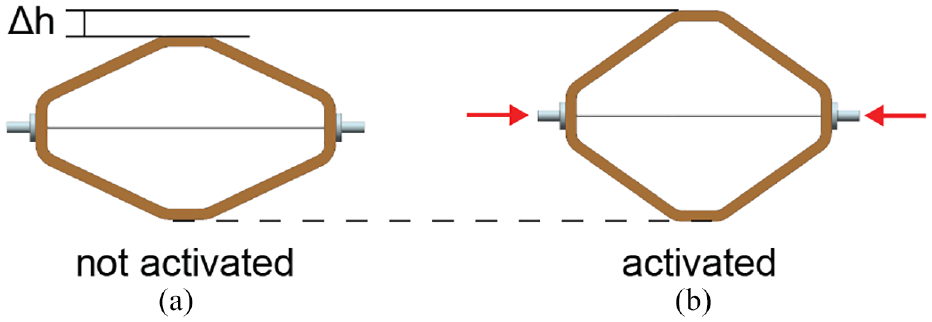
Working principle of the active joint: (a) SMA wire pre-strained and leaf spring undeformed and (b) SMA wire contracted and leaf spring deformed.
3. Method
The morphing capability of the shape-adaptable sandwich panel was evaluated considering a panel composed of 3 × 3 cells. At first, a numerical model describing the actuation of the SMA wire and the mechanical behavior of a single active joint was developed and validated with experimental tests. In a second step, a demonstrator of the panel was built and tested to verify the capability of the concept to reproduce multiple shapes and to assume multiple curvatures.
3.1. Numerical model
A numerical routine describing the behavior of the active joints was developed in Matlab R2018b. The routine combines a FE model of the leaf spring with a numerical model of the SMA wire based on the work of Brinson (1993). The architecture of the numerical routine is depicted in Figure 3. The routine takes the electrical current applied to the SMA wire as input and calculates the deformation of the leaf spring evaluating the thermomechanical behavior of the SMA wire over discrete time increments starting from given initial conditions.
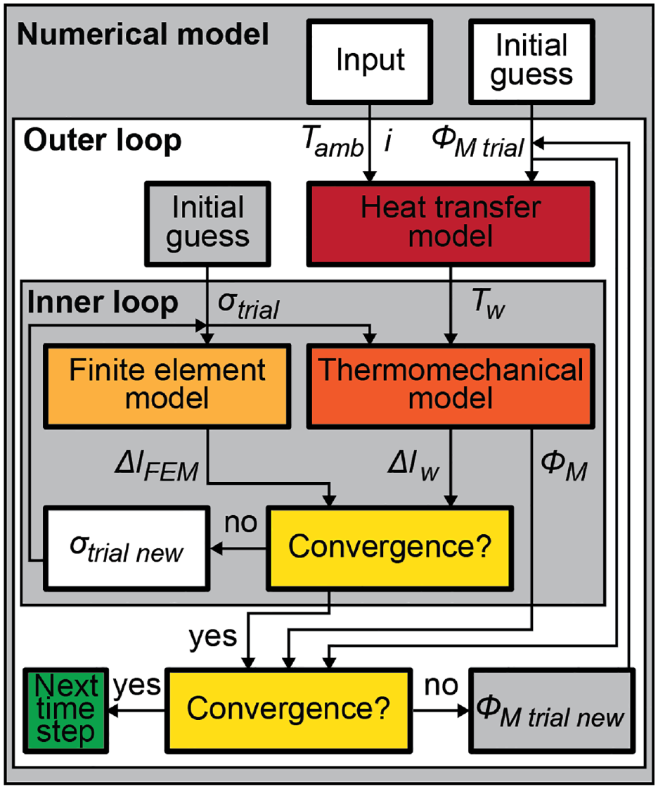
Architecture of the numerical routine modeling the behavior of the active joints.
The constitutive model of the SMA wire is composed of two sub-routines: an outer and an inner loop. The outer loop takes as inputs the applied current i, the ambient temperature Tamb, and a trial value of the martensite volume fraction ΦM trial, and uses a heat transfer model to calculate the temperature of the SMA wire Tw. Moreover, the outer loop compares the martensite volume fraction calculated by the inner loop ΦM with ΦM trial, and applies the Newton’s method to adjust the value of ΦM trial until the difference in martensite volume fraction between two consecutive iteration is lower than 1%. The inner loop receives as input the temperature of the SMA wire Tw calculated in the outer loop and a trial value of the stress of the wire σtrial, and uses a thermomechanical model of the SMA wire to calculate the corresponding strain εw, stroke Δlw, and martensite volume fraction ΦM. In addition, the inner loop converts σtrial into the corresponding force F and applies the latter in the FE model of the leaf spring to simulate the force exerted by the SMA wire on the leaf spring. The FE analysis returns the relative displacement of the attachment points of the SMA wire to the leaf spring ΔlFEM, which is then compared with the stroke of the SMA wire previously calculated. Finally, the value of σtrial is adjusted iteratively using the Newton’s method until the difference between the stroke calculated with the Brinson model and that returned by the FE analysis is lower than 0.1 mm. At this point, convergence is reached in the inner loop and the current value of ΦM is returned to the outer loop. When both loops have converged, the model saves the results and moves to the next time step until all time steps are covered.
3.1.1. Heat transfer model
At each iteration of the outer loop, the temperature of the SMA wires is calculated considering the balance between the energy generated in the wire, given by the sum of the Joule heating EJE and of the latent heat energy of the phase transformation ELH, and the energy dissipated by convection EC and that stored in the wire ES (Terriault and Brailovski, 2011):

The Joule heating can be calculated as:

where R is the resistance of the wire and
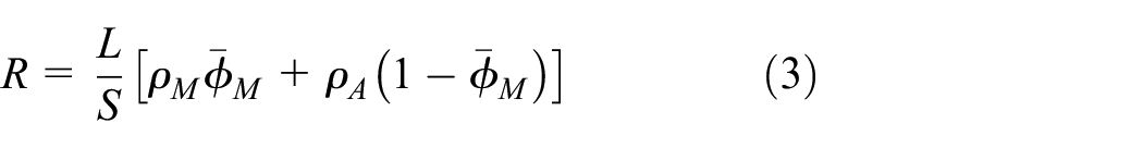
where L is the length of the SMA wire, S its cross section,
The latent heat energy is the product of the latent heat of the phase transformation QPT, of the volume of the SMA wire (V = S L) and of the variation of martensite volume fraction ΔΦM:

Assuming the case of natural convection, EC can be calculated as:

where h is the coefficient of natural convection, L and P the length and the perimeter of the SMA wire, respectively, and
The energy stored in the wire ES is the product of the specific heat Cp, the mass of the wire, which is given by the density d times the volume of the wire V, and the temperature increment in the wire ΔTw:

Combining equations (1)–(6), the temperature increment in the SMA wire is calculated as:
3.1.2. Thermomechanical model
The thermomechanical model for describing the behavior of SMA wire suggested by Brinson is based on the previous efforts of Tanaka et al. (1986), who first derived the constitutive relation for SMA wires. Neglecting the contribution of thermal expansion, the strain of the SMA wire can be expressed as:
where E(ΦM) and Ω(ΦM) are the Young’s modulus of the SMA wire and the transformation tensor, respectively. These are defined as:


where EA and EM are the Young’s modulus of austenite and martensite, respectively, and εmax the maximum transformation strain of the SMA wire. The novelty introduced by Brinson in his work (Brinson, 1993) is the distinction of the martensite volume fraction ΦM into a stress-induced ΦS and a temperature-induced component ΦT:

The temperature-induced component corresponds to the twinned martensite, while the detwinned martensite is considered by the stress-induced component. The calculation of these two components is based on the stress-temperature phase diagram of the considered SMA alloy and uses different constitutive laws, which are reported in the Supplemental Appendix.
3.1.3. FE model
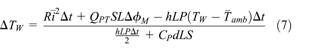
The FE model uses the Matlab Partial Differential Equation Toolbox to import a stereo lithography file of the leaf spring and calculate its deformation assuming a linear behavior. Referring to Figure 4, the active joints considered in this work were based on a leaf spring of height hl = 32 mm, width wl=52 mm, thickness tl = 6 mm, and arm thickness wa = 2 mm. A tetrahedral mesh with elements of size of 0.5 mm was used.
(a) Active joint and (b) shape-adaptable sandwich panel tested in this work.
3.2. Materials and manufacturing
The leaf springs were 3D printed (Indimatec) in polyether ether ketone (PEEK) (Zyex, VICTREX PEEK 1.75 mm) selecting a 60% rectangular infill and a single outer layer. This material was selected due to its high glass transition temperature, which lies above 140°C (Wu et al., 2015), in order to reduce the risk of thermal degradation during actuation. The Young’s modulus of the 3D printed PEEK was determined by testing five specimens with a universal testing machine (Zwick/Roell, Z005) according to the standard ASTM D790-10 (see Supplemental Appendix). The specimens were printed using the same machine and the same process parameters used for the leaf springs. A Young modulus of 2.860 GPa obtained from the tests was used to simulate the behavior of the leaf springs in the FE model. The material was modeled as isotropic with Poisson ratio of 0.4 (Arif et al., 2018).
With regards to the reference system in Figure 4(a), five leaf spring samples were tested under compression in x-direction in order to measure their elastic constant and validate the assumption of linear deformation of the FE model. The test was carried out in a universal testing machine (Zwick/Roell, Z005) at a speed of 5 mm/min. The test was also simulated Matlab R2018b using the FE model described in section 3.1.3. A fixed boundary condition was applied to the lower region of the leaf spring, which corresponds to the region in contact with the fixed part of the testing machine, while a predefined displacement was applied to the upper region of the leaf spring, which, in the test, is in contact with the movable part of the testing machine. The results, reported in the Supplemental Appendix, validate the assumption of linear behavior of the leaf spring for strains below 5%, which is lower than the maximum strain achieved during actuation, and returned an elastic constant of 21.5 N/mm.
The selected SMA wires (SAES Group, SmartFlex05) were a nickel-titanium alloy with a diameter dw = 0.5 mm, pre-strained by the manufacturer by 4.5%. They were crimped (SAES Group, T Type Crimp) to the outer side of the leaf springs (Figure 4(a)). A series of thermal and mechanical tests was carried out in order characterize the thermomechanical properties of the SMA wire. Differential scanning calorimetry (DSC) (Mettler Toledo DSC 1) was performed on a sample of 9.17 mg according to the ASTM F2004-17 standard to determine the latent heat of phase transformation QPT, the specific heat Cp, and the start and finish temperatures of the austenite and martensite phase transformation As, Af, Ms, and Mf. The Young’s modulus of austenitic phase of the SMA EA was determined by testing five specimens in a displacement controlled tensile test (Zwick/Roell Z005 AllroundLine) at a constant temperature of 100°C following the ASTM F2516-18 standard. Analogously, a tensile test was carried out at room temperature to identify Young’s modulus of the martensitic phase EM as well as the critical start σs crit and finish stress σf crit of the de-twinning process. The results of these tests are reported in the Supplemental Appendix.
A demonstrator of the shape-adaptable sandwich panel was built assembling the previously described active joints with the panel cells. The platelets and the truss elements composing the cells were 3D printed (Ultimaker 2+) in PLA (Swiss 3D Tec, PLA Filament 3 mm). The truss elements were printed separately, inserted in appositively designed notches in the cell platelets and soldered at an inclination angle of about 55°, since this angle is indicated to be the optimum angle for resisting compressive loads in pyramidal structures in the literature (Eichenhofer et al., 2017; Fan et al., 2006). In order to facilitate the connection with the active joints, each platelet was built with four anchor points for corresponding dovetail elements integrated in the active joints (Figure 4(a)). The active joints were connected using electrical wires and crocodile clips to allow for a quick reconfiguration of the electrical connections to realize different actuations patterns. Finally, contact paper was applied on the upper surface of each panel cell a speckle pattern, which was used to track the deformation of the panel using a digital image correlation (DIC) system (Figure 4(b)).
3.3. Actuation test
3.3.1. Single active joint
Five active joints were assembled and tested over five consecutives actuation cycles at room temperature. In each actuation cycle, the active joints were actuated for 30 s with a current of 2 A and let to cool down under natural convection for 60 s. The current was applied using a DC power supply (Keysight, E3631A). A DIC system (Correlated Solutions, VIC-3D) was used to track the displacement of four tags, applied on the crimps and on the dove tail elements of the leaf springs, respectively, to extract the contraction of the wire Δl and the stroke of the active joint Δh. The results were compared with the numerical simulations and used to tune the numerical model by adjusting the value of the coefficient of natural convection h to properly fit the experimental results.
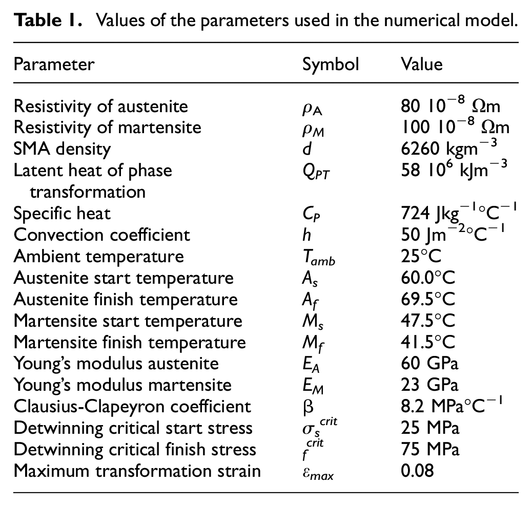
The values of the parameters used in the numerical model are listed in Table 1.
Values of the parameters used in the numerical model.
3.3.2. Shape-adaptable panel
The capability of the shape-adaptable sandwich panel to morph into different shapes was investigated experimentally. The panel was fixed on the lower surface of the central cell, while all the other cells were free to move. The active joints were powered for 60 s with a current of 2 A according to four different actuation patterns depicted in Figure 5 and explained below. A digital image correlation (DIC) system (Correlated Solutions, VIC-3D) was used to measure the deformation of the panel at time steps of 0.5 s during the entire actuation process and the data generated was analyzed with Matlab R2018b.
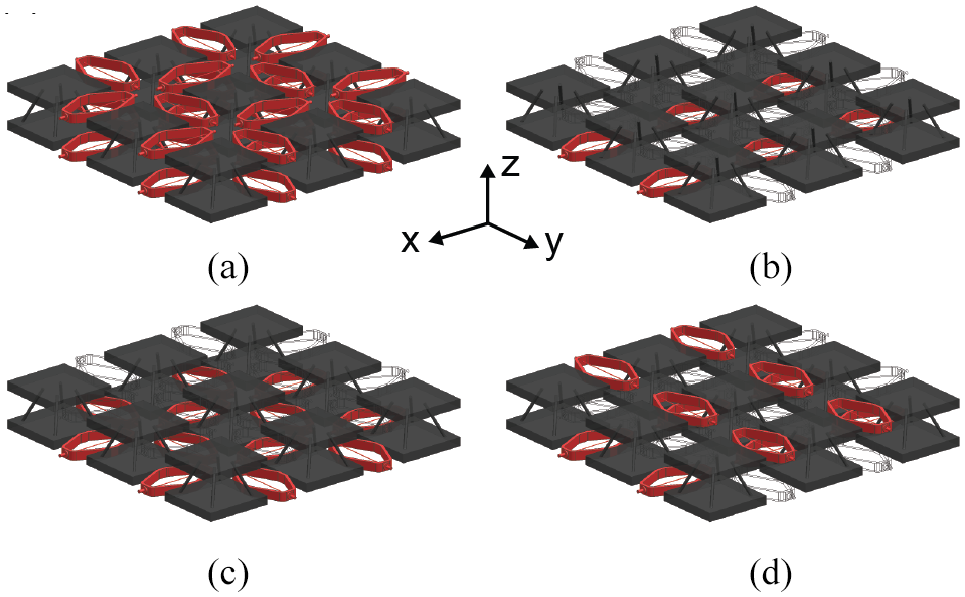
Actuation patterns of the active compliant joints:(a) planar expansion, (b) single curvature, (c) double curvature, and (d) saddle. The actuated active joints are marked in red.
3.3.2.1. Planar expansion
All active joints are actuated simultaneously (Figure 5(a)). In this way, the cells of the panel move apart the same distance in both x- and y-direction and the panel undergoes an in-plane deformation.
3.3.2.2. Single curvature
Only the active joints on the lower face sheet aligned in x-direction are actuated (Figure 5(b)). The lower face sheet of the panel expands in y-direction. The panel cells rotate and lift returning an overall U-like shape about the x-axis.
3.3.2.3. Double curvature
All active joints in the lower face sheet are actuated (Figure 5(c)). The lower face sheet expands both in x- and in y-direction, deforming the panel into a concave dome.
3.3.2.4. Saddle
The simultaneous actuation of active joints in both the upper and the lower face sheets gives us the possibility to achieve shapes that are even more complex. Here, on the upper face, the active joints aligned in y-direction are actuated, while, on the lower face, those aligned in x-direction (Figure 5(d)). The resulting shape is a saddle, where both a positive and a negative curvature are present.
4. Results
4.1. Single active joint
The simulated and measured strain of the SMA wire in the active joint are reported in Figure 6. When actuated with 2 A, the SMA wires contract from the initial strain of 4.5% to an average value of 0.5%. After the removal of the current, the SMAs recover on average a strain of 4.3%. All samples behave similarly and the difference in maximum achieved contraction and recovered strain amounts on average to 3.8%. The numerical results are in good agreement with the average values and predict correctly the maximum contraction of the SMA wires and the recovered strain. However, the simulation cannot replicate precisely the transient behavior of the active joints.
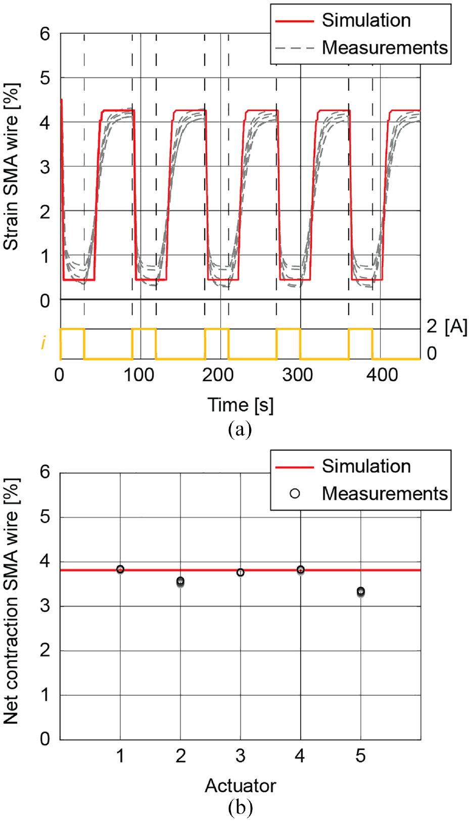
(a) Simulated and measured strain of the SMA wires of the active joints when actuated with a current i = 2 A for 30 s and let cool down under natural convection for 60 s over five actuation cycles. (b) Net contraction of the SMA wire in the five active joints tested.
4.2. Panel
Figure 7 depicts the deformations of the demonstrator for the four actuation patterns considered. In the case of planar expansion, we notice that the panel cells translate in radial direction from the center of the panel. The measured values of this translation were 3.1 mm for the cells at the center of the panel edges and 4.4 mm for those at the vertex, respectively. In the case of single curvature, the experimental results returned an average rotation of the external cells of the panel aligned in x-direction of 4.6° and a measured curvature of 0.17 m−1. A rotation α = 4.6° was also measured in the case of double curvature, leading to a measured curvature of 0.17 m−1 both in xz- and in yz-direction. Also in the case of the saddle, the rotation amounted to ±4.6°, while the measured values of the curvature were −0.18 and 0.17 m−1 in xz- and in yz-direction, respectively.
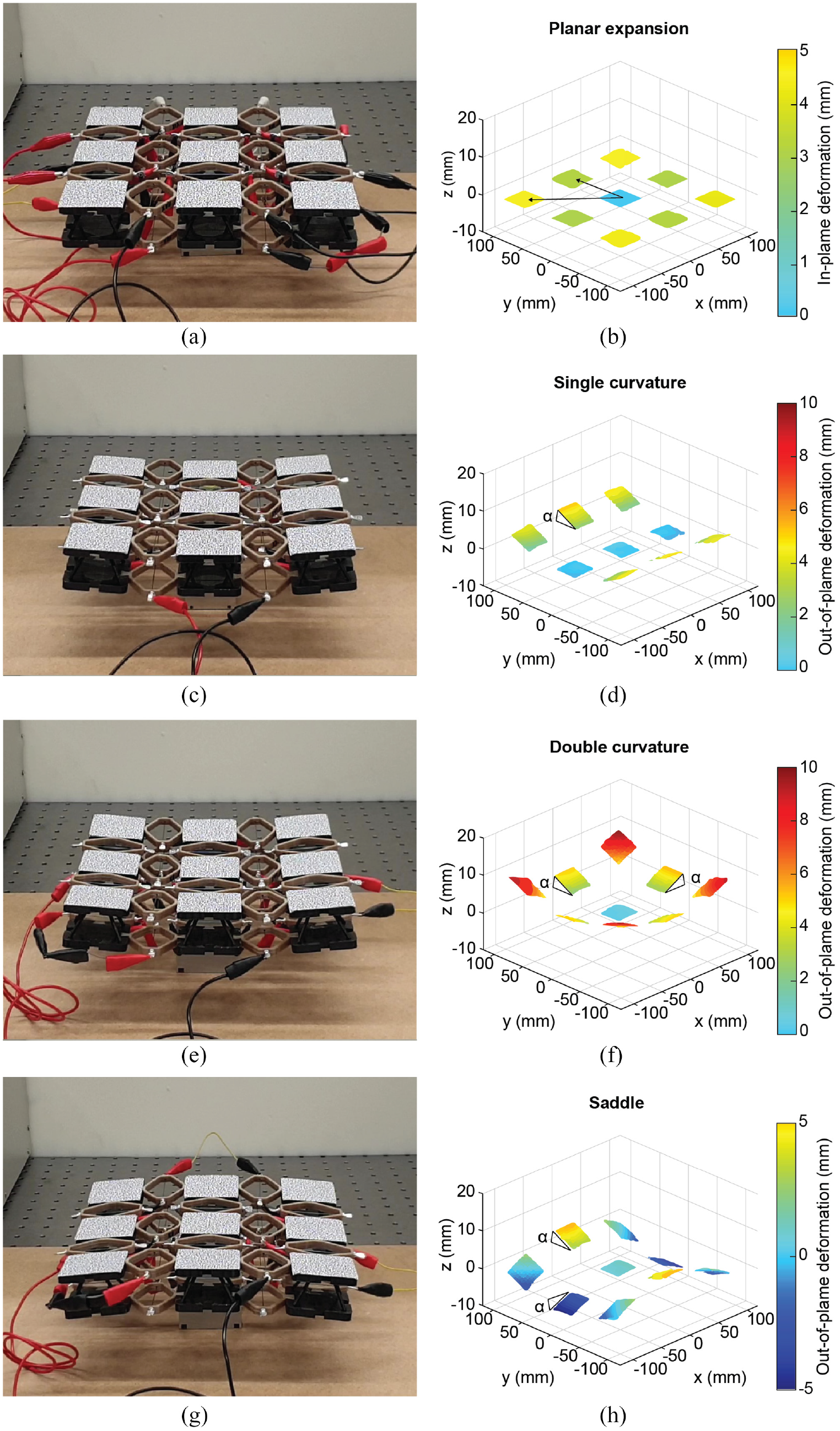
Pictures and DIC measurements for the four actuation patterns investigated: (a and b) planar expansion, (c and d) single curvature, (e and f) double curvature, and (g and h) saddle.
5. Discussion
The results not only prove the capability of the active joints to achieve multiple actuation cycles using a one-way SMA wire as actuator, but also show that a repeatable actuation can be achieved only from the second actuation cycle. Since the SMA wires were inserted in the leaf springs already pre-strained, they do not apply any force to the leaf springs before the first actuation, due to the clearance between the crimped ends and the leaf spring. Therefore, SMA wires and leaf springs start exchanging forces only during the first actuation of the SMAs. From this point onward, the tension in the SMA wires is balanced by the elastic force of the leaf springs. The latter allows for the re-straining of the SMA wires while cooling and determines both the maximum contraction of the SMA wires as well as their recovery strain. The difference between the maximum contraction of the SMA wires and their recovery determines the net contraction of the SMAs and the deformation of the leaf springs.
As far as the numerical model is considered, the results of the simulations demonstrate the ability of the model to accurately predict both the maximum contraction and the recovery strain of the SMA wires in the leaf springs but return some limitations in modeling the transient behavior. This fact can be justified by the net subdivision of the stress-temperature phase diagram of the material in regions with different constitutive equations. In reality, the boundaries of these regions are not sharp. This fact might explain the smoother transition between the minimum and the maximum strain measured in the experiments. Moreover, only natural convection has been considered in the heat transfer model, while other heat exchange mechanisms such as conduction, forced convection, and radiation might be also present.
The tests carried out on the panel show the capability of the proposed concept to reproduce multiple shapes in a controlled manner. The distributed actuation system and the modularity of the structure assure a large number of reproducible shapes and the possibility to tailor the initial configuration of the panel to the desired application. This might facilitate not only the achievement of different target shape, but also the integration of the panel into a larger construction by fixing only few cells. Additionally, the use of composite materials and novel manufacturing techniques (Fasel et al., 2020) might facilitate the integration of the additional components and the scalability of the concept while keeping a low weight. We envisage that structures similar to those presented in this work might find application as morphing aerodynamic structures to improve fuel efficiency and reduce noise. Another application might be in reconfigurable structures for a passive phased antenna arrays in space applications to save weight, space, and cost by providing satellites or space crafts with a single system capable of performing multiple tasks by varying the radiation pattern (Christodoulou et al., 2012).
6. Conclusions and outlook
This paper proposes a novel design of shape-adaptable sandwich panel with a network of distributed active joints based on SMA. A numerical routine is developed to predict the behavior of the active joints, which show a repeatable performance over multiple actuation cycles. A demonstrator of the sandwich panel is built and tested to demonstrate its capability of achieving multiple shapes, involving in-plane and out-of-plane deformations, with single or multiple curvatures.
The results allow us to conclude that the proposed concept of shape-adaptable sandwich panel represents a suitable candidate for the realization of smart structures capable of changing their shape multiple times in various and complex manners to perform multiple functions or to adapt to different working conditions in order to increase the efficiency or the performance of a system.
Further work should consider the operational life of the active joints, studying the effects of cyclic thermal loads on the fatigue and creep behavior of the SMA wire and of the leaf spring. Moreover, the performance of the active joints in a service environment has to be investigated which will vary from one application of the joint to another. In order to guarantee a repeatable performance in variable environments, a close loop control system must be developed. Finally, sensors and additional components might be integrated in the panel to measure the relative position of the cells and enable the autonomous actuation of the panel.
Supplemental Material
sj-pdf-1-jim-10.1177_1045389X211057203 – Supplemental material for A novel concept of modular shape-adaptable sandwich panelwith distributed actuation basedon shape memory alloys
Supplemental material, sj-pdf-1-jim-10.1177_1045389X211057203 for A novel concept of modular shape-adaptable sandwich panelwith distributed actuation basedon shape memory alloys by Oleg Testoni, Sandro Christen, Sampada Bodkhe, Andrea Bergamini and Paolo Ermanni in Journal of Intelligent Material Systems and Structures
Footnotes
Declaration of conflicting interests
The author(s) declared no potential conflicts of interest with respect to the research, authorship, and/or publication of this article.
Funding
The author(s) disclosed receipt of the following financial support for the research, authorship, and/or publication of this article: The authors would like to thank the ETH board for funding the project. The Digital Image Correlation (DIC) equipment was purchased through the Swiss National Science Foundation R’Equip grant 206021_150729.
Supplemental material
Supplemental material for this article is available online.
References
Supplementary Material
Please find the following supplemental material available below.
For Open Access articles published under a Creative Commons License, all supplemental material carries the same license as the article it is associated with.
For non-Open Access articles published, all supplemental material carries a non-exclusive license, and permission requests for re-use of supplemental material or any part of supplemental material shall be sent directly to the copyright owner as specified in the copyright notice associated with the article.