
Abstract
Civil engineering structures are susceptible to collapsing when exposed to severe vibrations. Therefore, it is essential to protect them from undesirable vibrations triggered by natural calamities like earthquakes or strong winds. This paper proposes an innovative semi-active Magnetorheological (MR) inerter system with a compact structure for seismic protection. The inerter system consists of four rubber bearings and the semi-active MR inerter. The inertance of the semi-active MR inerter can be switched according to different working scenarios. This unique operating principle enhances the adaptability of the system. To assess the performance of the proposed inerter system, a scaled three-storey building was constructed following scaling laws. Four scaled earthquake signals with different dominant frequencies were used as ground motion excitations. An inertance switch controller based on short-time Fourier transformation (STFT) methodology was built to determine the desired inertance of the inerter. Both the simulation and experimental results indicated that the proposed semi-active MR inerter system provides superior vibration mitigation capacity over the passive inerter systems. Specifically, the employment of the semi-active MR inerter effectively reduces the acceleration responses of the structures under different seismic excitations.
1. Introduction
In recent years, the threat of earthquakes has led to a growing concern for the safety and stability of civil engineering structures such as buildings, bridges and towers. Various methods have been developed to mitigate the damaging effects of seismic events on these structures. Among these methods, the inerter, as a two-terminal device that generates equal and opposite forces on its two nodes, was first proposed by Smith (2002). The magnitude of the reaction force is proportional to the relative acceleration between the nodes, with the proportional ratio defined as inertance and measured in kilograms. Inerters can be realised through various structures with a high transmission ratio, allowing them to exhibit a large apparent mass despite being lightweight (Dai et al., 2019; Wang et al., 2022; Zhao et al., 2021). As such, the inerter is a superior two-node alternative to the traditional one-node mass element. Before the development of the inerter, mass elements were utilised in the mechanical-electrical analogy as the mechanical counterpart of capacitors. However, the mass element has to be connected to ground potential constantly, and they do not exhibit the two-terminal characteristic of capacitors, which hinders the development and employment of the analogy theory. Fortunately, the introduction of the inerter resolved this contradiction and completed the analogy theory, enabling the application and investigation of knowledge of capacitors and electrical fields in mechanical systems through the use of inerters (Ning et al., 2021; Zhong et al., 2020). Inerters can convert translational movement into rotation movement through various mechanisms, including ball-screw (Jin et al., 2021; Smith, 2020; Yuehao et al., 2021), rack-and-pinion (Papageorgiou et al., 2009), as well as hydraulic (Nakaminami et al., 2017; Wang et al., 2011) and fluid inerters (Chillemi et al., 2023; Swift et al., 2013), etc. Papageorgiou et al. (2009) conducted a comprehensive experimental investigation into the dynamic behaviour of ball-screw and rack-and-pinon inerters. The results obtained from the experiments demonstrate that the admittance of both inerters can be closely approximate that of an ideal inerter. The experimental findings also highlighted the presence of frictional losses within the mechanical structures can lead to deviations from the ideal inerter’s dynamic behaviour. Wang et al. (2011) introduced a novel hydraulic inerter, which generates the inertance by utilising a flywheel driven by a hydraulic motor. The proposed inerter was subjected to extensive experimental validation, with dynamic properties thoroughly studied. Based on the experimental results, the authors developed a theoretical model that accurately describes the dynamic responses of the hydraulic inerter. Another hydraulic based inerter is known as fluid inerter, where the inertance is produced by the fluid flowing in a helical channel rather than the rotations of flywheels. Shen et al. (2016) developed a nonlinear model of a fluid inerter, considering the effects of damping, friction and inertance elements. The model was experimentally validated by prototyping the fluid inerter, and the results showed that the model was effective in low frequency. In addition, some other unique inerters were proposed such as living-hinge inerter (John and Wagg, 2019), crank inerter (Zhang et al., 2022) and electromagnetic inerter (Gonzalez Buelga et al., 2015). Intensive studies have been conducted on the applications of inerters in different fields of mechanical, civil and ocean engineering field (Ma et al., 2021; Xu et al., 2022).
Compared to other mechanical elements such as stiffness and damping, the application of inertance elements in commercial settings is relatively rare. Semi-active controllable stiffness and damping concept have been extensively studied using various methodologies, especially with MR technology (Deng et al., 2022, 2023; Jin et al., 2023; Nordin et al., 2022; Yang et al., 2020), however, most of the inerters developed and investigated so far are passive in nature. The lack of semi-active inerters greatly limits their further improvement and research, and to fully complete the electrical-mechanical analogy, controllable inertance concept is becoming increasingly important in academic research. In addition, when inerters are used to protect civil structures, a pre-set inertance can increase the vibration mitigation capacity at some specific frequencies but degrade its effectiveness at other frequencies. Therefore, designing inerters involves a trade-off. To mitigate the limitations of traditional passive inerters, several studies have investigated the design and implementation of semi-active inerters. These inerters offer the advantage of being able to adjust their inertance in real-time, enabling them to provide optimal performance under varying operating conditions. Hu et al. (2016) proposed a novel controllable flywheel system that uses a linear actuator to adjust the radius of gyration, thereby allowing for the manipulation of inertance. Zhang et al. (2018) introduced a semi-active device with an adjustable inertance, consisting of a hydraulic cylinder and a displacement-related inertance cylinder. This device enables the control of inertance by modifying the position of the piston within the inertance cylinder. Lazarek et al. (2019) conducted an investigation into an inerter integrated with a continuously variable transmission (CVT) mechanism, whose inertance can be changed continuously by altering the transmission ratio of the system.
However, the implementation of previous semi-active inerters has been hindered by their complex structures and considerable physical dimensions, making them challenging to be applied in practical scenarios. To overcome this limitation, in this paper, the authors propose a novel semi-active inerter that incorporates Magnetorheological fluid (MRF) bearings, which enables a more compact size while maintaining performance efficacy. This system provides a switchable inertance determined by the frequencies of seismic events. The variation in inertance allows the semi-active inerter system to suppress vibrations across various seismic frequencies than the passive inerter systems. The structure of this paper is presented as follows. Section 2 provides a detailed description of the entire inerter system, including schematic diagrams, working principles, prototyping and characterisation. In Section 3, after introducing the inertance switch control loop, the advanced vibration suppression ability of the semi-active MR inerter system is demonstrated through numerical simulations. The corresponding experimental validation is presented in Section 4. Finally, the conclusion is stated in Section 5.
2. The structure, working principle and characterisation of the semi-active MR inerter
The semi-active MR inerter system comprises four rubber bearings and a semi-active MR inerter. It is intended to be installed between the first floor of the scaled building and the ground. The schematic diagram and prototype of the inerter system are represented in Figure 1. The mechanism study, prototyping, and characterisation of the semi-active inerter are described in this section.
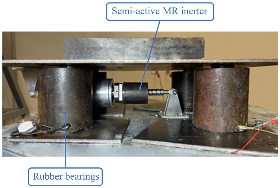
The prototype of the semi-active MR inerter system.
The conventional ball-screw inerter is designed to operate solely in passive mode, with a fixed inertance determined by the pre-set flywheel part. The lack of adaptability may lead to negative consequences for civil structures under various seismic events. Specifically, the inability to adjust the inertance in real time can exacerbate the impact of resonance, potentially leading to significant structural damage or failure. To address these limitations, in this paper, a semi-active MR inerter with switchable inertance shown in Figure 2 is designed and manufactured. The proposed semi-active inerter differs significantly from the conventional ball-screw inerter by incorporating a controllable flywheel system comprising a primary flywheel, a sub-flywheel, two MRF-bearings and solenoid coils. The MRF-bearings utilised in the proposed semi-active inerter design contain MRF within their internal chambers (Zhu et al., 2023), with their inner rings being rigidly connected to the primary flywheel and their outer rings connected to the sub-flywheel. In the low inertance state, the primary flywheel and the sub-flywheel are decoupled. Hence, the translational movement between its two nodes is converted into the rotational motion exhibited by the primary flywheel solely, resulting in a low level of inertance. Conversely, when the MRF is activated, the raceway of the bearing becomes immobilised, resulting the simultaneous rotation of both the primary and sub-flywheels. In this case, the inerter system exhibits a notable high inertance characteristic. This innovative design allows for real-time adjustment of the inertance level of the inerter, thus enabling greater adaptability and more effective control over the dynamic response of civil structures.
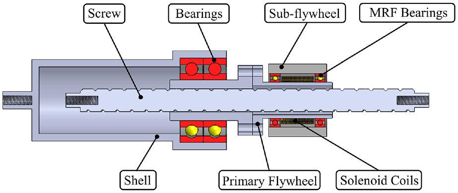
The mechanical structure of the semi-active inerter.
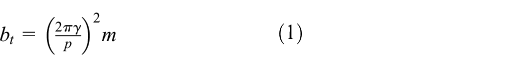
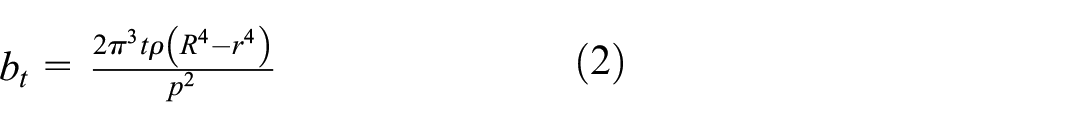
The inertance of the semi-active MR inerter can be mathematically calculated as:
where,
where,
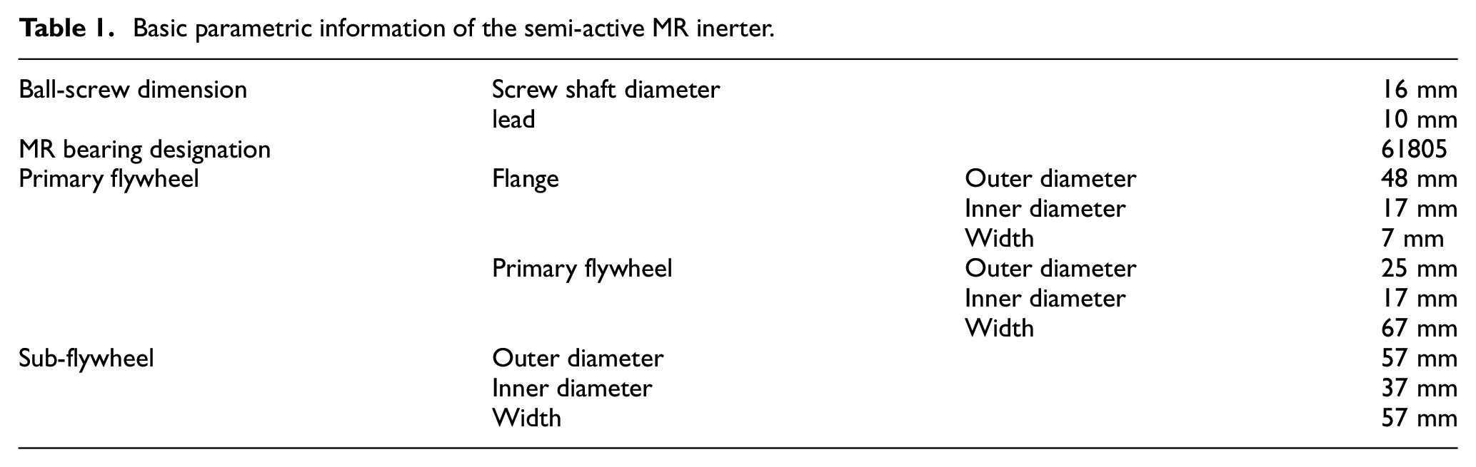
The basic parametric information of the semi-active MR inerter is listed in Table 1, which includes the dimensions of the flywheel system, the bearing selection, and the ball-screw specification. Through the parametric study, the inertance of the semi-active inerter in the low inertance and high inertance state can be calculated to be approximately 40 and 190 kg.
Basic parametric information of the semi-active MR inerter.
To assess the viability and efficacy of the proposed controllable flywheel system, a magnetic field simulation was carried out using COMSOL software, and the result is depicted in Figure 3. The simulation analyses the magnetic flux density in the MRF active region, denoted by segments AB and CD in Figure 3(a). When the solenoid coils are applied with a current of 3 A (Figure 3(b)), the MRF active region was subjected to a magnetic field with a minimum flux density of 0.4 T. This magnitude of flux density was considered to be adequate to induce the activation of the MRF and facilitate the locking of the inner ring with the outer ring of the bearing, thus achieving a high level of inertance.
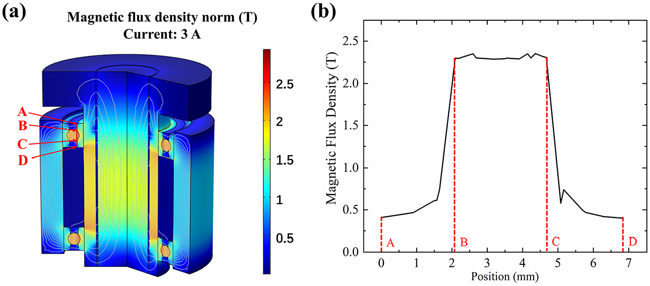
Magnetic field simulation: (a) magnetic flux density and path and (b) magnetic flux density passing through MRF at different positions.
To provide further experimental validation of the proposed inerter system, a semi-active MR inerter prototype was characterised by a Landmark servo-hydraulic test system (MTS system). The tests were conducted in two parts, including frequency dependency and amplitude dependency tests.
The frequency dependency test result demonstrating the dynamic response of the proposed semi-active MR inerter under harmonic excitations with a constant amplitude of 3 mm and varying frequencies ranging from 2 to 6 Hz is illustrated in Figure 4. The slope of the force-displacement loops indicates the equivalent stiffness. It could be observed that, in both the low inertance state (0 A) and the high inertance state (3 A), the equivalent negative stiffness increased with the increase of the frequency. When the semi-active MR inerter worked in the low inertance state, the force increased from approximately 20 to 150 N as the frequency varied from 2 to 6 Hz. Similarly, in the high inertance state, the peak force raised from roughly 50 to 900 N.
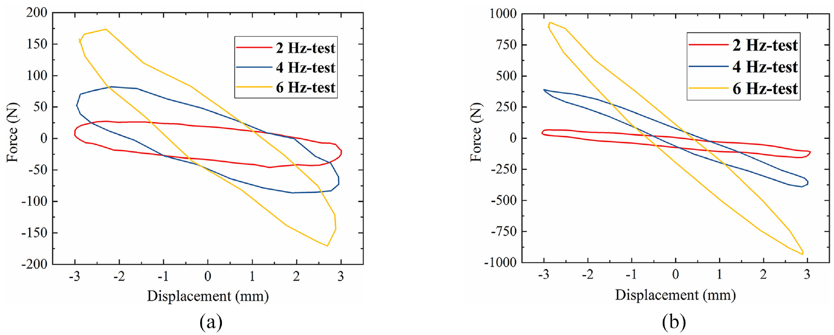
Frequency dependency test results: (a) low inertance case (0 A) and (b) high inertance case (3 A).
In the amplitude dependency tests, the frequency of the excitation was set as 3 Hz, and the harmonic amplitude increased from 3 to 7 mm with an increment of 2 mm. Figure 5 demonstrates that increasing the amplitude boosted the force response of the semi-active inerter. For the low inertance case, the peak force increased from 30 to nearly 100 N, while the peak force raised from around 125 to 625 N for the high inertance case.
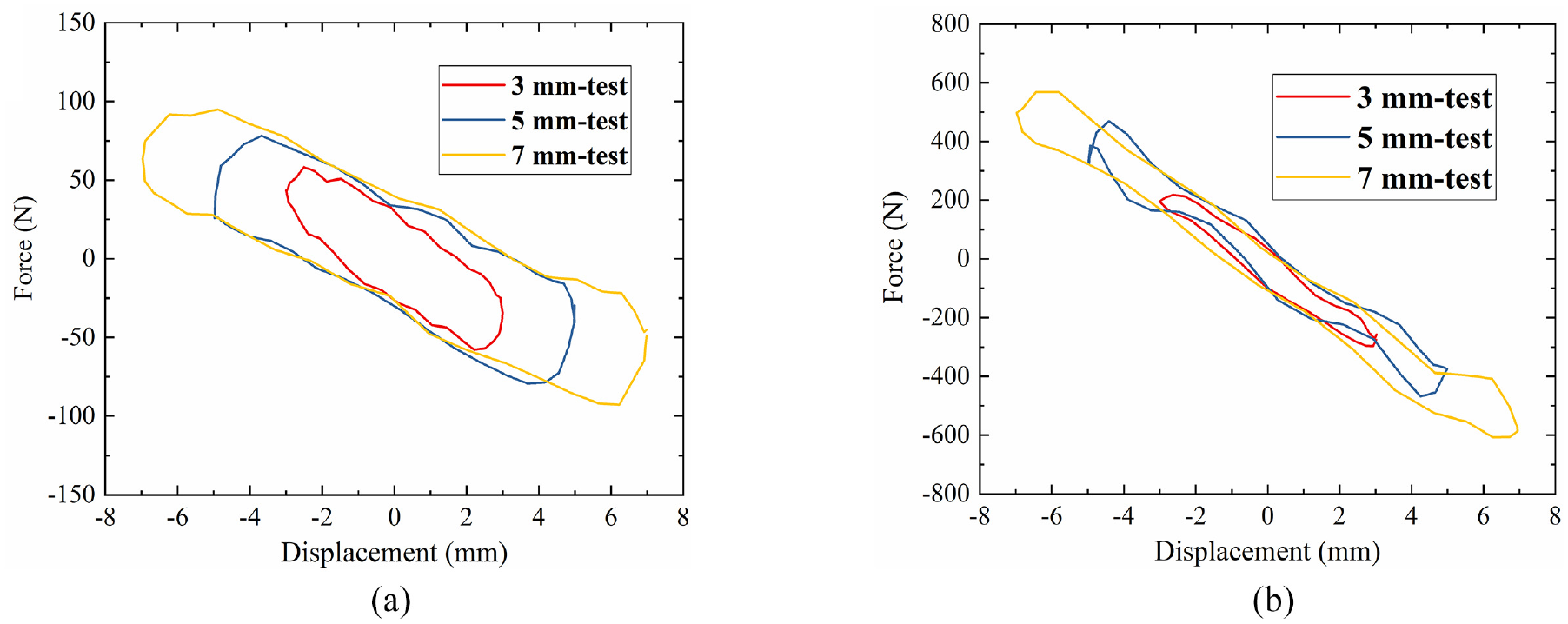
Amplitude dependency test results: (a) low inertance case (0 A) and (b) high inertance case (3 A).
To enhance the precision of the theoretical analyses and ensure a closer alignment between the theoretical and experimental results observed in the inerter characterisation, a theoretical model was developed for the semi-active MR inerter. This model was informed by detailed observations and analyses of experimental data. Within this framework, three primary linear components were identified: inertance, stiffness and damping. However, a key challenge emerged in the amplitude-dependent mechanical properties inherent to the semi-active MR inerter. These properties rendered fixed-parameter models inadequate for capturing the mechanical characteristics across various loading amplitudes.
To overcome this challenge, the proposed model incorporates amplitude-dependent elements for both damping and stiffness element, thereby enhancing its adaptability and accuracy in representing mechanical responses under different loading scenarios. This dynamic model is schematically illustrated in Figure 6. Furthermore, considering the dual-state feature of the semi-active MR inerter, specifically, its low and high levels of inertance, two distinct yet principle-aligned models were developed. Each model utilised a unique set of parameter values. This bifurcated modelling approach ensures a compressive and precise representation of the semi-active MR inerter’s dynamic characteristics.
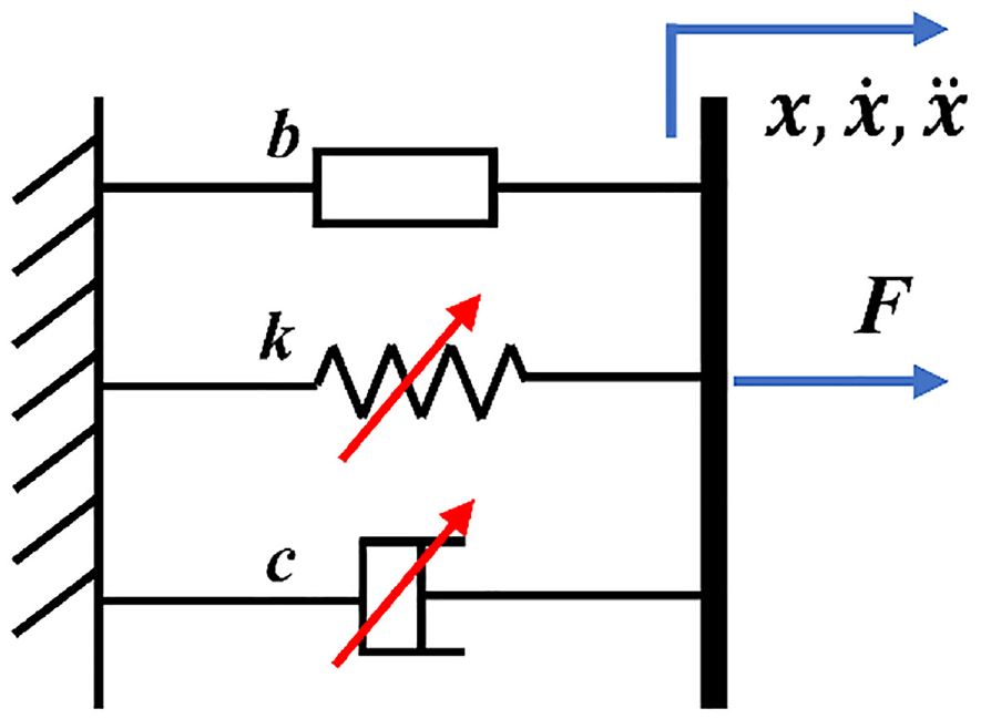
Dynamic model of the semi-active MR inerter.
The force generated by the semi-active MR inerter can be calculate as:

where
The inertial force

where


where
The comparison between the experimental data and the simulation data was shown in Figure 7, indicating good agreement between the two for different loading amplitudes and frequencies.
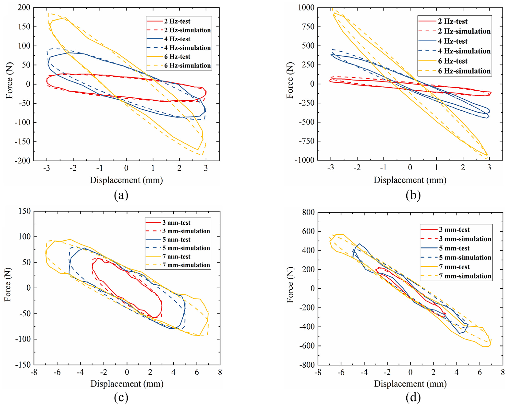
The comparison between the test and simulation results for the semi-active MR inerter under tow levels of inertance (0 A and 3 A).
3. Theoretical evaluation of the proposed inerter system
3.1. Design and modelling of a scaled building system
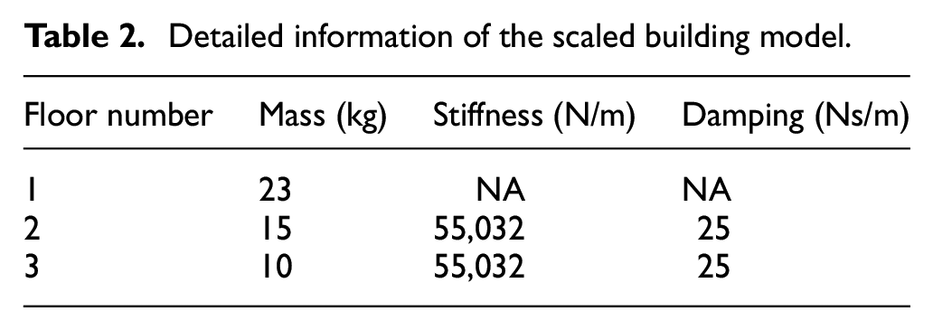
A scaled three-storey building was established to evaluate and validate the advanced vibration attenuation performance of the new inerter system. According to the scaling law (Mills, 1979), the height scale ratio and the time ratio was deigned to be 1:9 and 1:3, respectively. Hence, the acceleration of the scaled building can be identical to that of the corresponding full-scale building. The details of the building model are outlined in Table 2.
Detailed information of the scaled building model.
The dynamic model of the whole scaled building system installed with the new inerter system was developed, as shown in Figure 8. The dynamic equations can be expressed as:
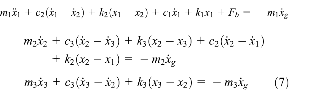
where,
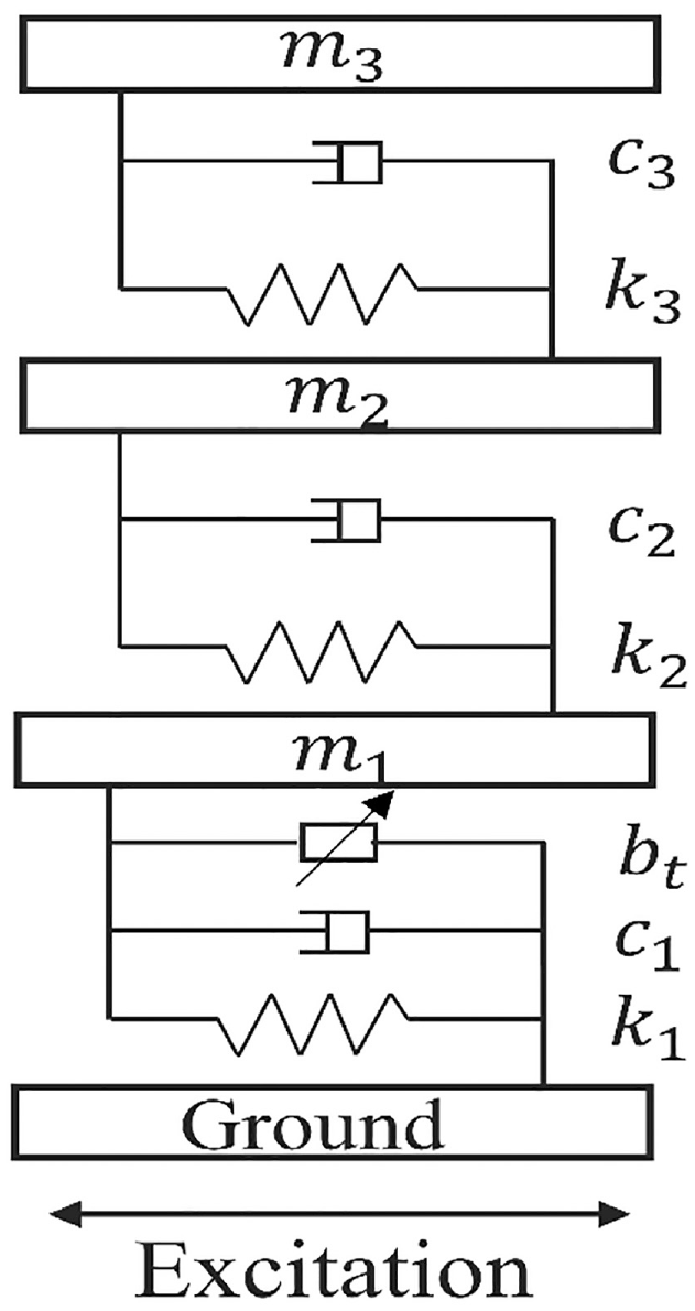
The scaled building system.
3.2. Controller design for the semi-active MR inerter system
This section describes an inerter inertance switch controller based on the short-time Fourier transformation (STFT) to avoid the resonance of the scaled building system, by achieving lowest transmissibility and minimising dynamic responses. The occurrence of resonance in the scaled building system can arise irrespective of whether the system is in the low or high inertance state. In order to prevent such resonance, it is necessary to dynamically adjust the real-time inertance based on the system frequency. This entails continuously monitoring the system’s frequency response and adjusting the inertance to ensure optimal vibration isolation performance. By implementing this approach, the detrimental effects of resonance can be mitigated, resulting in improved performance and increased safety of the system.
From the experimental tests presented in Section 4.2, it is known that the best vibration reduction performance featuring by the lowest transmissibility can be realised by applying high inertance and low inertance in different frequency ranges. The distinct frequency ranges are divided by a certain frequency
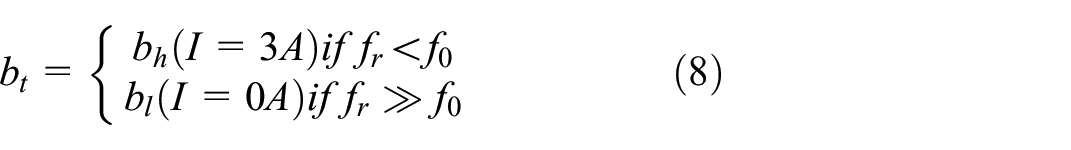
where,
The control strategy flowchart is depicted in Figure 9. Firstly, the accelerations at the third level of the scaled structure are monitored in real-time using an accelerometer. Then, the signals are processed through STFT methodology, to identify the dominant frequency of the building’s vibrations in real time. STFT is a widely employed methodology to analyses dynamic signals through dividing the signals into small time segments and applying Fourier analysis to each segment to identify the frequencies in each segment. The calculation principle is shown as follows:

where

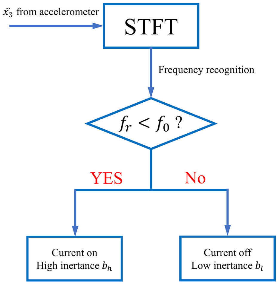
The control strategy flowchart.
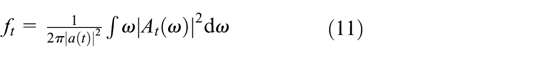
The real-time frequency at time t can be calculated by:
Upon determining the real-time vibration frequency, it is compared against the switching frequency
3.3. Simulation results and analysis
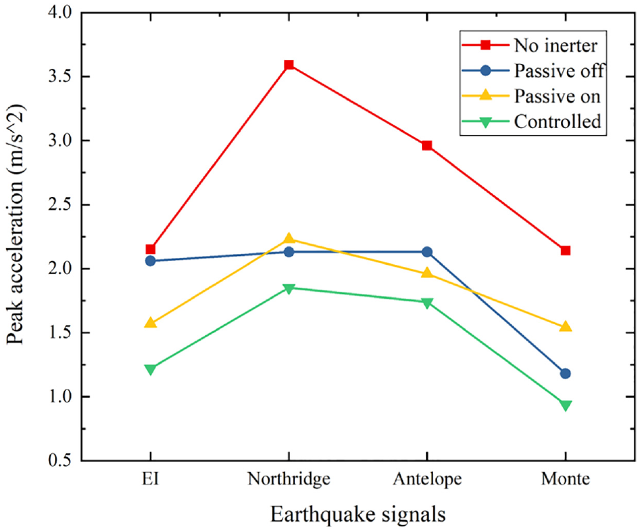
The semi-active MR inerter system presented in this paper is anticipated to outperform passive inerter systems. For comparison purposes, three additional isolation systems were evaluated through simulations, which are as follows: (1) No inerter, in which only the rubber bearings were employed without any inerters; (2) Low inertance, in which the inerter operates in the passive low inertance case with rubber bearings; (3) High inertance, in which the inerter operates in the high inertance state with rubber bearings and (4) Controlled inertance, in which the semi-active inerter is controlled in real-time to switch between the low and high inertance states. In the simulation study, four scaled earthquake signals with various dominant frequencies were utilised as excitations. The theoretical model of the scaled building system was established in MATLAB/Simulink, which included the scaled three-storey building, the semi-active MR inerter system, the inertance switch controller based on STFT methodology. Regarding the evaluation of the seismic vibration suppression performance, the evaluation criteria for assessing the performance of the system include the acceleration of the third floor
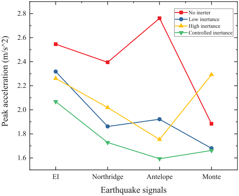
Simulation results of the peak accelerations.
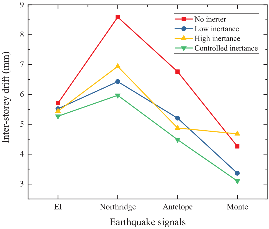
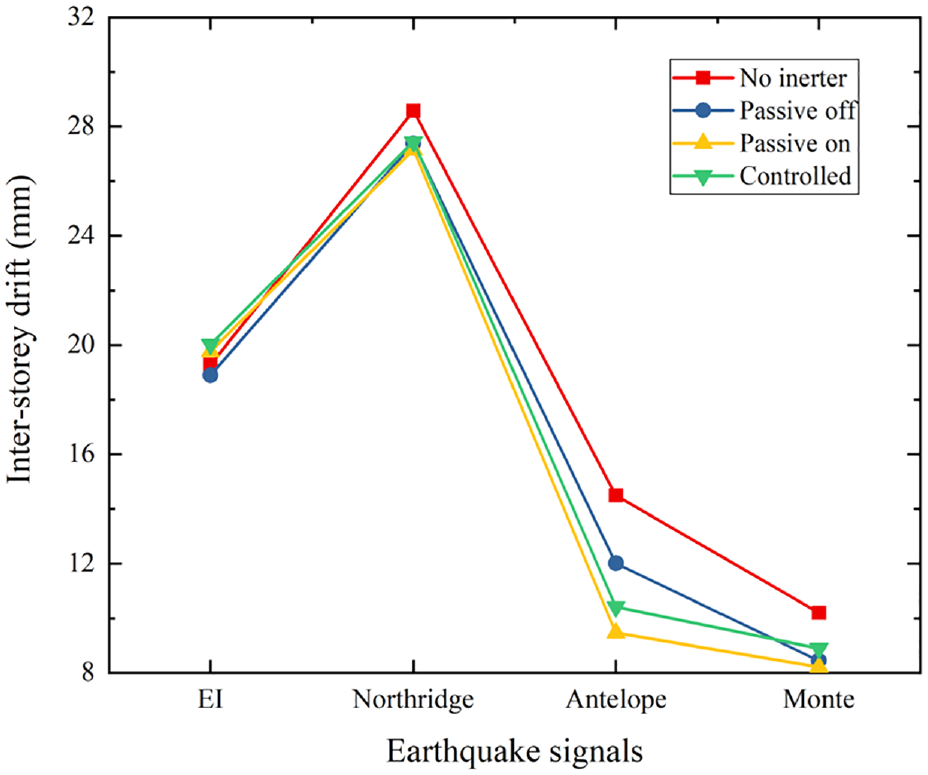
Simulation results of the peak inter-storey drifts.
The simulation results demonstrated that the proposed semi-active inerter system outperformed the other three passive systems. Specifically, the controlled inertance system achieved the best performance with the lowest peak floor acceleration reduction and inter-storey drift magnitude. Numerically, compared the controlled inertance case with the no inerter case, the peak acceleration decreased by 18.8%, 27.8%, 43.5% and 11.8% under four different seismic excitations, respectively. Correspondly, the peak inter-storey drift was reduced by 7.7%, 30.5%, 33.5% and 24.8%. Although the passive low inertance and passive high inertance modes provided improved vibration mitigation performance compared to the no inerter case, they were not suitable for all four excitations, as their vibration-mitigation-effective frequency band was narrow. In contrast, the controlled inertance case demonstrated consistent and efficient vibration mitigation for different seismic excitations, indicating its robust and reliable performance in real-life scenarios.
4. Experimental evaluation of the proposed inerter system under various excitations
4.1. Experiment setup
The experimental evaluation setup is illustrated in Figure 12. The whole testing system includes three laser sensors, two accelerometers, a six degrees of freedom (6-DOF) vibration platform, two computers (PC 1 and PC 2), a scaled three-storey building and the proposed semi-active MR inerter system. The 6-DOF platform comprises six hydraulic cylinders that are accurately controlled by an NI CompactRIO controller to track the displacement command. PC 1 provides displacement command to the NI CompactRIO, which then drives the vibration platform to simulate the real earthquake vibrations from the ground to civil structures. During the vibrations, the laser sensors and the accelerometers continuously record the dynamic response information and output data to PC 2 via NI myRIO. The designed STFT methodology and control loop identify the dominant frequency within each sampling window of the excitations and output the desired current commend to NI myRIO, manipulating the inertance levels using the power amplifier. Hence, the real-time control of the semi-active inerter system is realised.
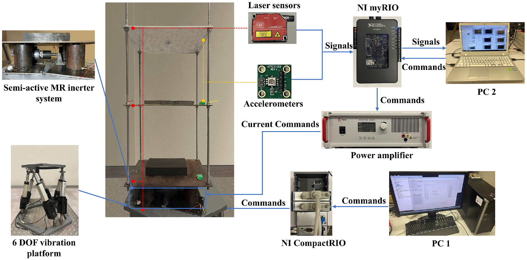
Schematic diagram of the experimental setup.
4.2. Transmissibility tests
The identification of switching frequency and validation of the anti-resonance capacity of the inerter was conducted through transmissibility tests on the scaled building system under three different isolation systems: (1) No inerter; (2) Low inertance and (3) High inertance. A frequency sweep signal with a stable amplitude ranging from 0.5 to 5 Hz was employed. As depicted in Figure 13, the transmissibility plots of the three cases were presented. It was observed that the introduction of the inerter in the low inertance state decreased the transmissibility at resonance frequency from 7.5 to 4.2, while the first-order resonance phenomenon displayed a left-shift feature in the frequency domain due to the apparent mass provided by the inerter on the building. In the high inertance case, the first-order resonance transmissibility was further reduced from 4.2 to approximately 2.1, exhibiting an anti-resonance capacity. However, the left shift of the first-order resonance also shifted the second-order resonance, resulting in a much stronger resonance with a transmissibility of 6.3. The transmissibility testing results reveal that it experiences a single resonance peak in the low inertance state, whereas in the high inertance state, two distinct resonance peaks are observed. This finding underscores the significance of inertance magnitude switching as a crucial factor in avoiding resonance and enabling the realisation of advanced wide-band vibration isolation performance. In Figure 13, the intersection of the transmissibility curves corresponding to low and high inertance is noted at a frequency of 3 Hz. As delineated in Section 3.2, this frequency is identified as the switching frequency
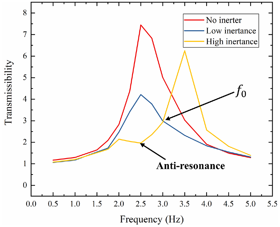
The transmissibility plots under three isolation systems.
4.3. Experimental evaluation excited by scaled earthquake signals
The four scaled earthquake signals originate from four earthquakes named after the cities affected by the disasters, namely, EI Centro, Northridge, Antelope and Monte were selected as excitation signals. With the given earthquake signal excitations, four isolation systems were evaluated: (1) no inerter; (2) low inertance; (3) high inertance and (4) controlled inertance, respectively. In the controlled inertance scenario, the inertance of the semi-active are dynamically switched in real-time, governed by the output of the STFT controller. A visual representation of this mode switching process is anticipated to be presented in Figure 14, where the current is given according to the required inertance (high/low levels). Given the compact configuration of MRF bearings, demagnetisation is critical during the transition from the high inertance state to the low inertance state mode. Failure to execute demagnetisation may result in the MRF bearings retaining active, thereby impeding the intended inertance switch. Consequently, during experimental trials, when the operating mode undergoes a switch from the high inertance state to the low inertance state, the MRF bearing will be subjected to a decreasing and alternating magnetic field to ensure rapid demagnetisation.
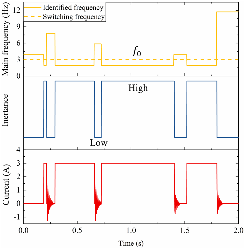
The current control process example.
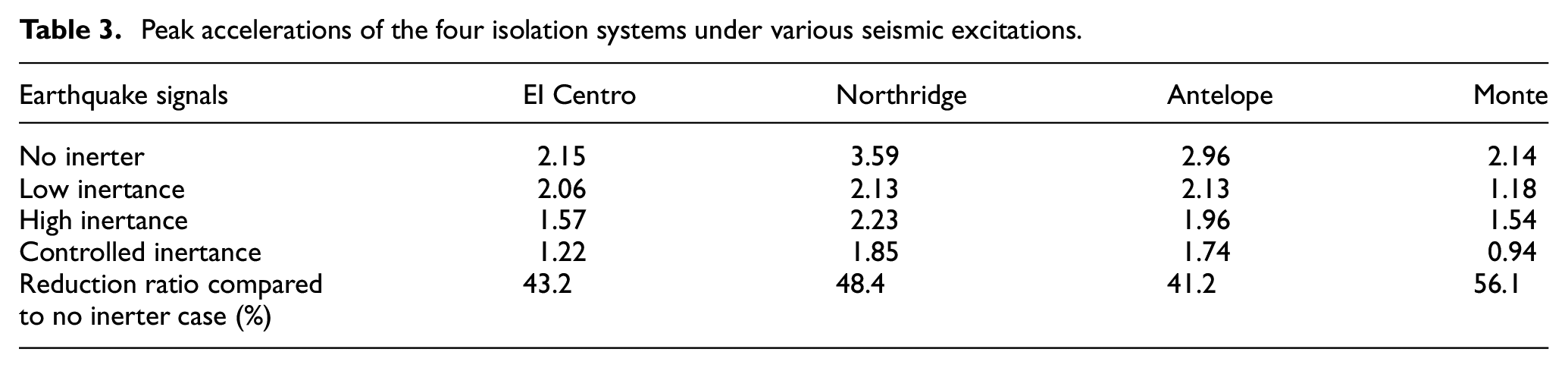
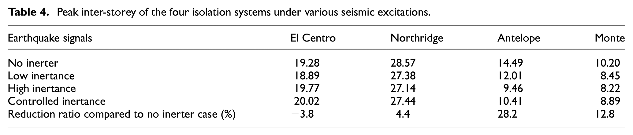
Figures 15 to 18 showcase the acceleration and inter-storey drift responses of the four isolation systems evaluated under four scaled earthquake signal excitations. Notably, the controlled inertance case, which employs a semi-active MR inerter with switchable inertance, exhibits superior vibration mitigation performance in terms of acceleration response compared to the remaining three isolation systems. The results of the peak accelerations and inter-storey drifts were presented in Figures 19, 20 and Tables 3, 4. It is indicated that the utilisation of the semi-active inerter system resulted in a significant reduction in peak accelerations for all four seismic excitations. However, the peak values of inter-storey drifts did not consistently exhibit a reduction pattern. Specifically, the peak inter-storey drifts demonstrated a decrease under two seismic excitations, while remaining nearly constant for the remaining two seismic excitations. Two primary reasons can account for this phenomenon. Firstly, the utilisation of STFT analysis to determine dominant frequencies primarily relied on the acceleration signal instead of the displacement signal. This approach was taken due to the heightened sensitivity of acceleration to frequency. As a result, the inertance switching of the semi-active system was governed based on acceleration instead of inter-storey drifts. Secondly, the experimental evaluations revealed that the inerter prototype consistently required an initial activation force, which may result in a lag in the inerter operation. In cases where inter-storey displacement was not reduced, the peak displacement occurred at the onset of vibration, producing a shock-like response rather than a typical vibration response. This impairs the semi-active inerter system aseismic ability. It is worth noting that despite the aforementioned concerns, the generalised inter-storey drifts under the scaled four seismic excitations were reduced by 6.7%, 8.7%, 26.9% and 16.3%, respectively, in the Root-Mean-Square (RMS) values. Overall, the experimental results demonstrate that, compared to passive inerter systems, the semi-active MR inerter system can adapt to different vibration frequencies, thus significantly mitigate floor accelerations without compromising inter-storey drifts, even under various seismic events.
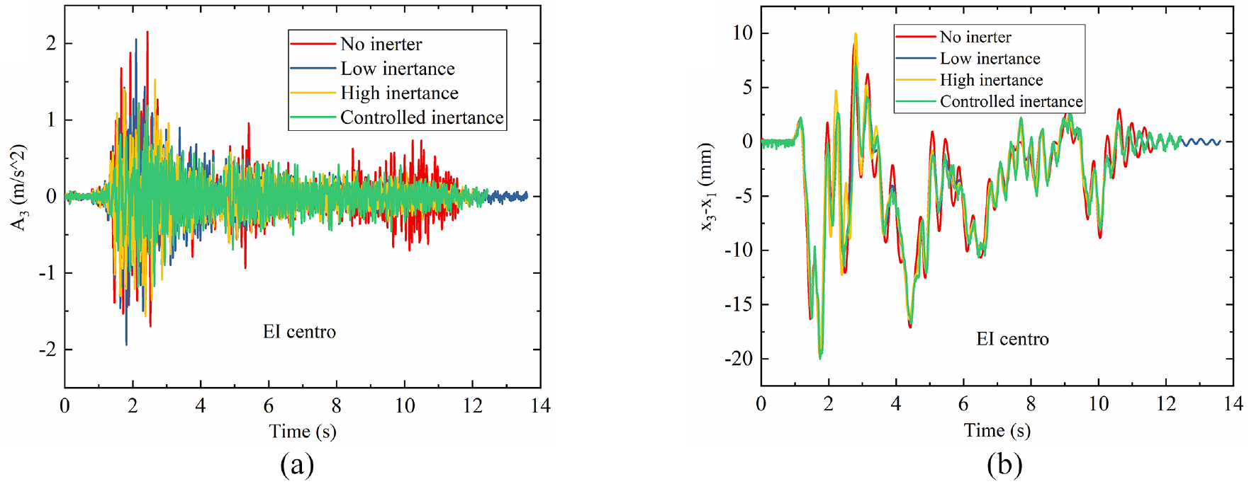
The dynamic response of the scaled building under EI Centro scaled signal: (a) acceleration of the third floor and (b) inter-storey drifts.
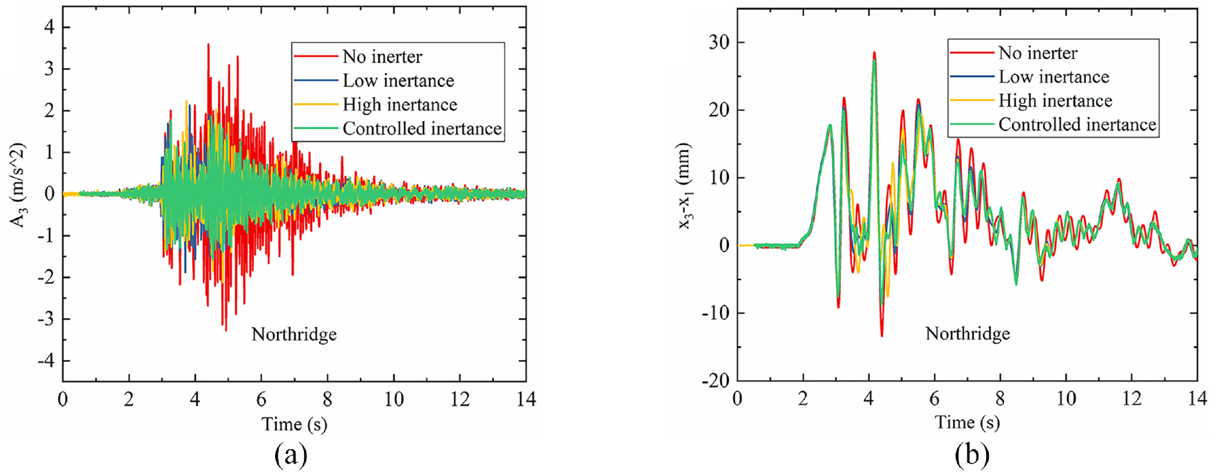
The dynamic response of the scaled building under Northridge scaled signal: (a) acceleration of the third floor and (b) inter-storey drifts.
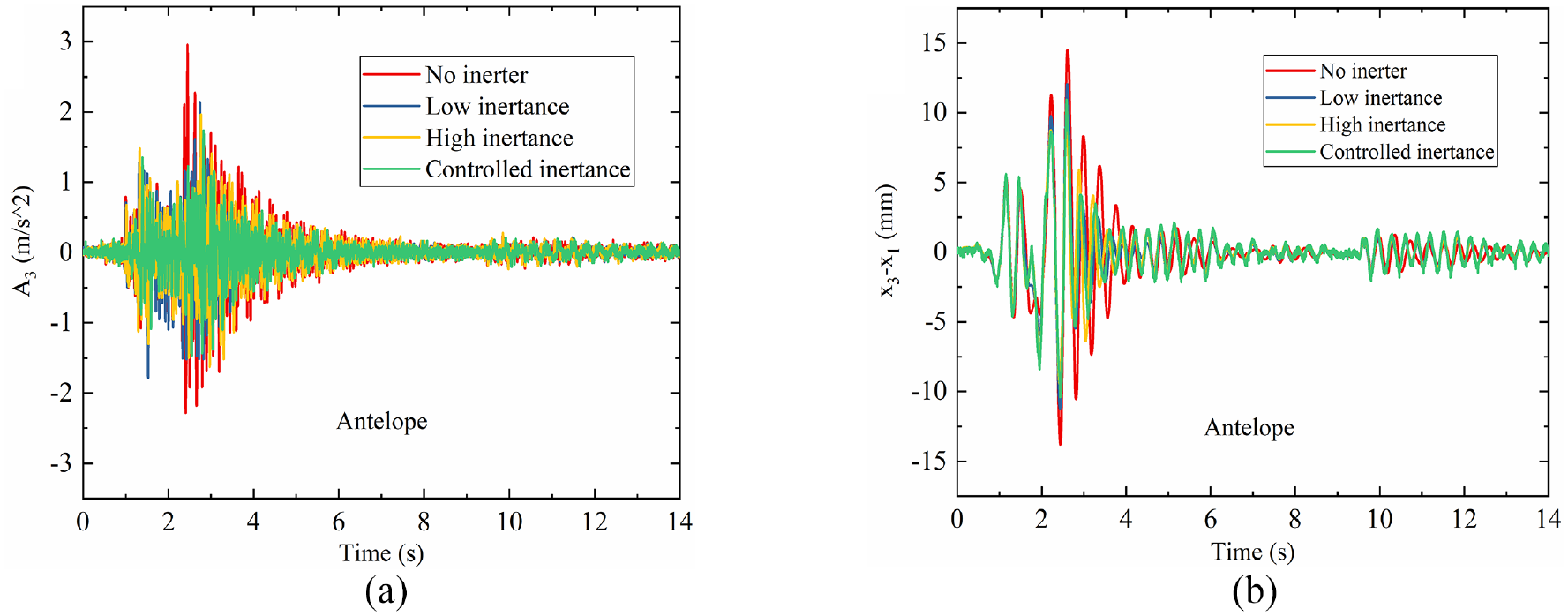
The dynamic response of the scaled building under Antelope scaled signal: (a) acceleration of the third floor and (b) inter-storey drifts.
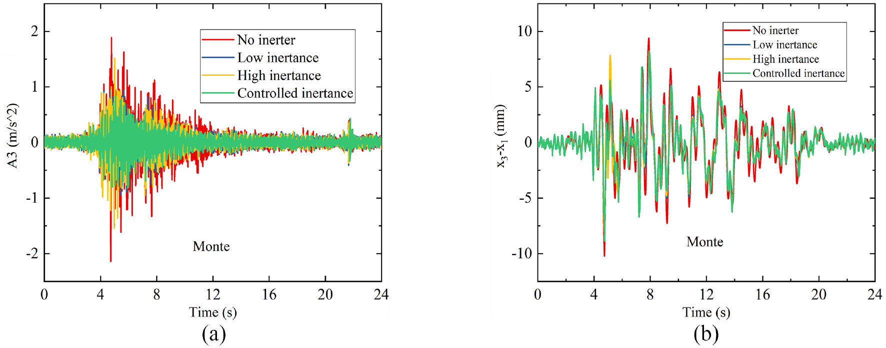
The dynamic response of the scaled building under Monte scaled signal: (a) acceleration of the third floor and (b) inter-storey drifts.
Experimental results of the peak accelerations.
Experimental results of the peak inter-storey drifts.
Peak accelerations of the four isolation systems under various seismic excitations.
Peak inter-storey of the four isolation systems under various seismic excitations.
5. Conclusions
This paper presents the development of a novel semi-active MR inerter system designed to enhance aseismic performance. To evaluate the efficacy of the proposed inerter system, a scaled three-storey building was constructed and subjected to four scaled seismic excitations. The numerical and experimental study results demonstrate that the novel semi-active MR inerter system provides superior peak floor acceleration reduction performance in various seismic excitations without amplifying inter-storey drift. Numerically, compared to the no inerter case, the controlled inertance case decreases the peak floor acceleration responses under four various seismic signal excitations by 43.2%, 48.4%, 41.2% and 56.1%, respectively. The system achieves wide frequency range vibration mitigation compared to passive inerter systems, making it effectively adaptable to various seismic events. Additionally, the integration of MRF bearings into the inerter systems extends the combination of MR technology and inerters, providing the possibility of designing continuously controllable semi-active inerters. These findings have significant implications for the design and implementation of robust vibration control systems that prioritise structural safety.
Footnotes
Funding
The authors disclosed receipt of the following financial support for the research, authorship, and/or publication of this article: This work was supported by the Australian Research Council Linkage Grant (No. LP190100603) and the Faculty PhD scholarships.
Declaration of conflicting interests
During the preparation of this work the authors used OpenAI ChatGPT in order to improve the language. After using this tool, the authors reviewed and edited the content as needed and take full responsibility for the content of the publication.
Data availability statement
All data that support the findings of this study are included within the article (and any supplementary files).