
Abstract
A novel lumped-element modeling approach for magnetic shape memory alloys is presented. Building on concepts borrowed from rate-independent plasticity, the model describes the magnetic and magneto-mechanical behavior of a magnetic shape memory component subjected to a particular load case in a thermodynamically consistent way. The approach remedies the common issues of existing models regarding the representation of inner hysteresis loops and small-signal behavior. The model is parametrized in terms of a small number of parameters, which can be determined from single variant magnetic curves and mechanical first order reversal curves at constant magnetic input. The results indicate that the model predicts the magnetic and magneto-mechanical behavior with sufficient accuracy, which makes it appropriate for system design.
1. Introduction
Single crystal magnetic shape memory alloys (MSMA), such as NiMnGa, exhibit comparatively large strains of typ. 6% in response to moderate external magnetic fields well below 1 MA/m due to twin boundary motion within their martensitic phase. For this reason, they are considered promising candidates for active elements in compact electromagnetic actuators, sensors, generators, and dampers. Since the first works in the middle of the 1990s (James and Wuttig, 1998; Ullakko et al., 1996), this class of active materials has gained a remarkable scientific attention, and a significant improvement with regard to alloy composition and magneto-mechanical properties (Wilson et al., 2007), fabrication technology (Kellis et al., 2012; Pagounis and Laufenberg, 2012) as well as operation temperature (Pagounis et al., 2014) has been attained. Despite these advances, the technology has not entered the market yet, although a multitude of demonstrators has been introduced for a variety of possible applications (Pagounis and Müllner, 2014; Pagounis and Schmidt, 2012; Schmidt and Quandt, 2010). One of the main technical reasons for this lack of commercialization appears to be the complexity of the design process of MSM-based actuator systems related to the nonlinear and hysteretic magneto-mechanical coupling of MSMA. Further complication arises from the fact that the performance of MSM actuators is a result of the mutual interaction of all contributing subsystems and mostly a tradeoff between contradictory design objectives. Taking these aspects into account, the need for a model-based design of MSM actuators is self-evident.
Different modeling approaches for the magneto-mechanical behavior of single crystal MSMA (mostly NiMnGa) have been published in the past. These may be roughly categorized into microscopic, macroscopic, state-space and lumped-element models (LEM).
A comprehensive overview of published constitutive models and how they build on each other can be found in Jafarzadeh and Kadkhodaei (2017), Kiang and Tong (2005), and LaMaster et al. (2015). Most of these microscopic and macroscopic models are based on continuum thermodynamics and on the minimization of free energy.
Microscopic models like Ahluwalia et al. (2006), James and Wuttig (1998), Mennerich et al. (2011), and Peng et al. (2016) consider the material behavior on the microscopic level with an explicit representation of the twinned structure. Usually, driving forces for twin boundary motion are computed as a function of the external loading, the material properties of the different domains, and their geometric arrangement. These models can enhance the basic understanding of coupling and allow for computing the load-dependent development of the twin structure evolution. However, due to the length scale to be resolved microscopic models are usually too expensive for actuator design with regard to computational cost.
The majority of published models describes the material state in terms of macroscopic quantities, which are based on a homogenization over the actual twin structure. The reader is referred to the papers mentioned above for an overview. LaMaster et al. (2015) note that a considerable part of the published models is purely two-dimensional, and many of them are restricted to load cases where magnetic and mechanical load are perpendicular to each other. Further, only one load is allowed to change in many models. These shortcomings have been overcome by several authors, for example, Bartel et al. (2021) and LaMaster et al. (2015). A difficulty is posed by the fact that twin boundaries typically extend along the entire sample width and, in addition, also the formation of broad twins has been reported (Aaltio et al., 2010; Marioni et al., 2004). As a consequence, the preconditions for homogenization implicit in many macroscopic models are not fulfilled. Moreover, the system response can be considered only in a very limited manner.
State-space system models are typically used for control applications, for example, for hysteresis compensation in position control (Binetti et al., 2015; Riccardi et al., 2012; Ruderman and Bertram, 2014). Usually, the entire electro-mechanical actuator behavior of an already existing MSM actuators is considered. Frequently, approaches are based on modified Preisach and Prandtl-Ishlinskii models. Although these models exhibit an exceptional prediction accuracy, they can hardly be used for system design since their prediction is limited to the particular (already existing) actuator used for parameter identification.
LEM consider the integral behavior of an MSM component subjected to a particular load case based on differential-algebraic equations without a spatial resolution of fields. Since the physical subsystems are explicitly represented, at least in a simplified manner, system design is readily possible. Although most of the models cited in the sequel are referred to as “one-dimensional constitutive models” with scalar input and output are formulated in terms of field quantities they consider only suitably defined effective values of the latter. Therefore, they are classified as LEM in this work.
Several authors adapted modeling approaches originally developed for thermally activated shape memory alloys (SMA) to MSMA (Bindl et al., 2012; Couch and Chopra, 2007; Guo et al., 2014). These approaches compute the martensitic volume fraction from approximation functions depending on load, direction, and current state. Similarly, the Tellinen hysteresis model, originally introduced to model the scalar ferromagnetic hysteresis, has, in a univariate (Suorsa et al., 2004) and a bivariate (Ziske et al., 2015) form, been adapted to MSM modeling. For the last two, only limiting hysteresis curves and surfaces, respectively, are required for their full parametrization, which is experimentally laborious for the bivariate version. Naturally, the large-signal behavior 1 is well represented in this class of models, especially if data are directly interpolated. In contrast, small-signal behavior (see Note 1) is poorly predicted to some extent, and, under certain conditions, an unphysical model behavior such as clockwise hysteresis drifting under cyclic loading occurs (Ziske et al., 2015). Also, thermodynamic consistency is not always ensured. Moreover, the magnetic behavior is not even considered in many models (Bindl et al., 2012; Couch and Chopra, 2007; Guo et al., 2014; Ziske et al., 2015). It has been attempted to overcome these issues with vector Preisach hysteresis models (Adly et al., 2006; Visone et al., 2010). However, implementation is complex, and parameterization is laborious since a considerable amount of first-order reversal curves (FORCs) in the full bivariate input space is required. LEMs building on continuum thermodynamics have been presented (Gauthier et al., 2007; Sarawate and Dapino, 2010). However, the agreement with practically relevant loading scenarios is only moderate and an appropriate minor loop prediction is not proven.
In early product design stages different principal variants of different underlying operating principles need to be evaluated regarding their desired system function. Usually, main dimensions and parameters are already determined, but a detailed design or layout does not yet exist. A model-based evaluation must consider this on an abstract level in consideration of all involved subsystems. An example might be the comparison of an electromagnetic and an MSM circuit breaker for a certain current range in several operating conditions. Modeling approaches based on generalized Kirchhoffian networks (LEM) are well suited to this purpose. Therefore, the latter approach is chosen below. In this context, it is aimed to use a minimum number of fitting parameters on the one hand while ensuring thermodynamic consistency and providing a sufficient prediction accuracy of large- and small-signal behavior on the other. The paper is structured as follows: Firstly, the modeling approach is described. Secondly, the necessary temporal discretization is discussed along with implementation aspects. Thirdly, the identification of parameters is exemplified. Finally, the model is verified by comparison with experimental data.
2. Model description
2.1. Chosen approach
Within this work, an approach based on rate-independent plasticity (Prandtl-Reuss) is chosen, which has been successfully extended to other coupled field problems in the past, especially to ferroelectric ceramics, see for example, Landis (2002). This procedure is transferred to the present problem in a dimensionally reduced form as a LEM. In particular, the magneto-mechanical terminal behavior of a specific sample (“component”) in a specific load case is considered, in which magnetic and mechanical loads are perpendicular to each other (Holz et al., 2012). Further, to emphasize the lumped-element character of the proposed model, we exclusively use component-related quantities (integral quantities, see below), which can also be measured directly (Ehle et al., 2020, 2021).
2.2. Considered load case
A cuboid, single-crystal MSM component with the volume

where
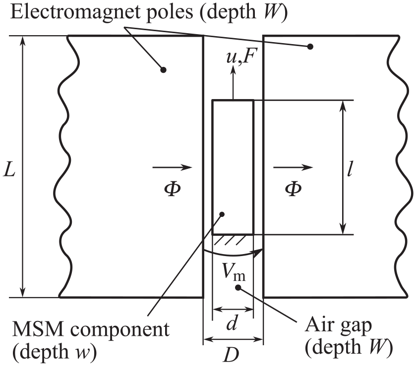
Schematic of the considered load case with relevant quantities and dimensions.
The MSM component is supported on one side of the mechanical loading axis, and an external force

can be defined, and the component length

changes accordingly. As discussed in more detail below, it is assumed that MIR preserves the volume and does not affect the depth
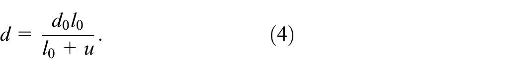
As part of this approximation, the area of the magnetically permeated component face also depends on the displacement:

Due to the non-negligible shape change of typ. 6% and more, the magnetic energy within the air gap is also displacement-dependent and contributes to the driving forces for MIR. For this reason, the magnetic behavior of the entire air gap will be considered, which is common practice in the modeling of conventional electromagnetic actuators. This unit comprising MSM component and air gap will be referred to as “MSM unit” below. As a positive side effect, Maxwell force contributions are automatically included in the considerations.
2.3. Additional assumptions
The following fundamental assumptions are additionally made for the model described below, based on the specific characteristics of the considered load-case, the aimed application, and experimental observations:
The elasticity of the component is neglected, so that the entire deformation of the component is ascribed to the motion of twin boundaries, since, for typically applied loads, the ratio between elastic and reorientation strain
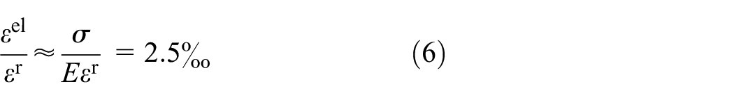
is negligible. The latter result is calculated with an applied compressive stress of
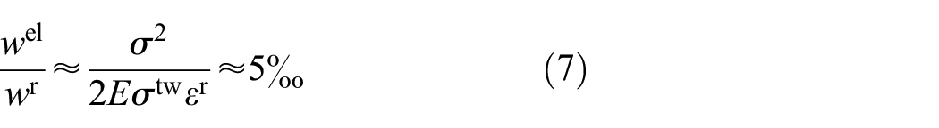
for the values assumed above and a twinning stress of
The time constants of practical magnetic circuits (defined by resistance and inductance) and mechanical loading mechanisms (defined by moving mass and reset spring stiffness) both typically lie in the single to double-digit millisecond range, as the evaluation of representative publications indicates (Faran et al., 2017, Henry et al., 2003, Minorowicz et al., 2016, Riccardi et al., 2014). This lowpass behavior limits both the step response and the large-signal magneto-mechanical frequency response to a few milliseconds and a few hundred hertz, respectively, see Aaltio and Ullakko (2000), Faran et al. (2017), Henry et al. (2003), and Tellinen et al. (2002). The practically attainable response times are thus at least two magnitudes larger than the reported intrinsic ones (Marioni et al., 2003, Saren et al., 2016). Thus, system dynamics will mainly determine the transient response of MSM actuators. Therefore, the lumped-element MSM component model is chosen to be rate independent.
The elongation of the component is changed thermodynamically irreversibly by MIR, while the change of magnetization is a thermodynamically reversible process in the absence of twin boundary motion. The latter assumption is based on the experimental observation of a negligible magnetic hysteresis in single variant states (Heczko et al., 2015).
Consistent with experimental results of tensile-compressive tests of different martensitic phases and twin boundary types (Söderberg et al., 2004, Straka et al., 2010, Suorsa, 2005), the twin boundary motion is associated with kinematic hardening behavior. That is, about twice the twinning stress needs to be overcome to reinduce reorientation upon load reversal.
The reorientation of martensitic variants is assumed to be volume-conserving.
Typically, investigated 5M NiMnGa single-crystal are cut along their {100} planes and undergo magneto-mechanical training in order to create a preferable twin structure, ideally consisting of only one type of twin boundaries and two types of martensitic variants (Heczko et al., 2009). Thus, it is assumed that the magnetic easy axes of the variants lie in the plane spanned by the magnetic and mechanical loading axes and are either parallel or perpendicular to the magnetic and mechanical loading axes.
Isothermal conditions are assumed throughout.
The intuitive viewpoint is adopted that the elongation of the MSM component is related linearly to the microstructural volume fraction of martensitic variants having their magnetic easy axis aligned with the magnetic loading axis.
Below, the general framework used to describe the response of an MSM unit for the time interval
2.4. Description of the thermodynamic state
The thermodynamic state of the MSM unit is described in terms of the state variables
2.5. Helmholtz free energy and external work
The Helmholtz free energy

where

Here and henceforth, a superimposed dot indicates the rate of a quantity.
2.6. Second law of thermodynamics
For the assumed isothermal situation, the second law of thermodynamics demands that

Using (8) and (9), this can be rewritten as
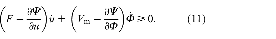
Based on the assumptions that the change of magnetization is a thermodynamically reversible process, while the motion of twin boundaries is a thermodynamically irreversible process, this inequality is satisfied as follows:
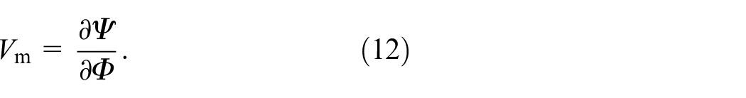
1. The magnetic voltage is related to the Helmholtz free energy by
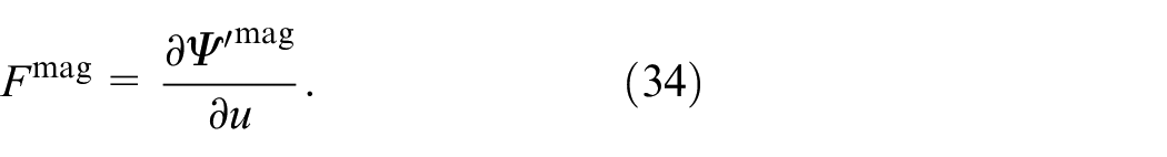
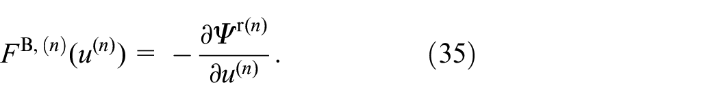
2. With regard to the mechanical part, a differentiable, convex “reorientation function”
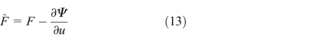
being the thermodynamic driving force for twin boundary motion. The reorientation function is assumed to be minimal for
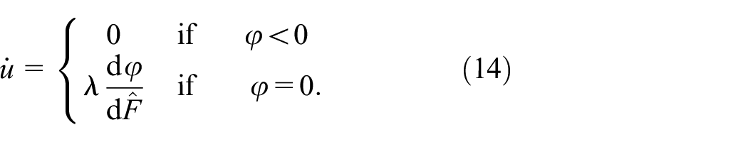
Here,
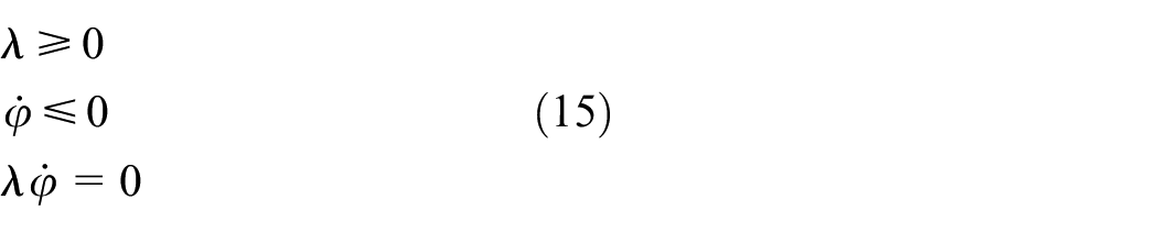
if
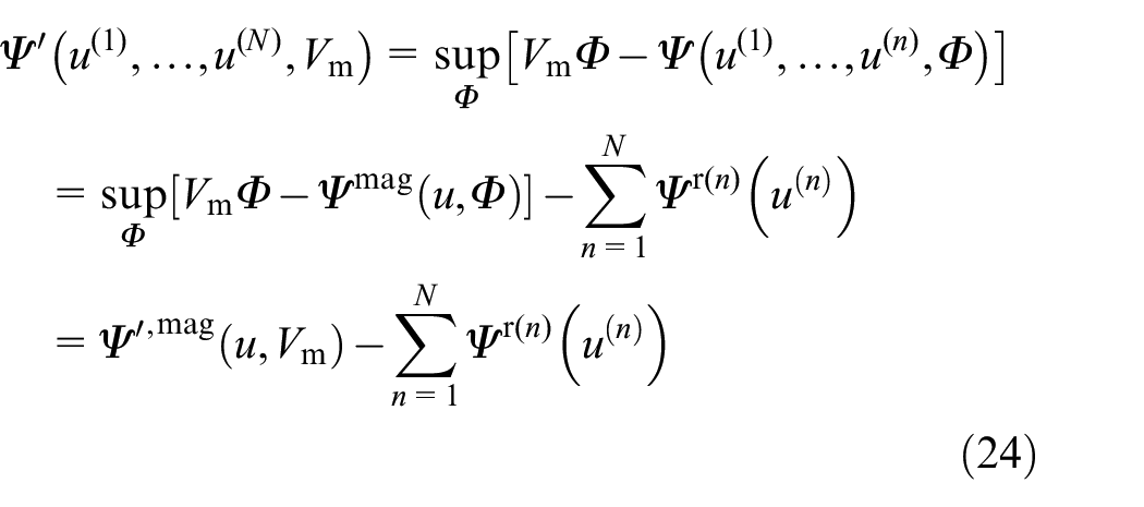
2.7. Co-energy
Due to the specifics of the magnetic behavior, it later turns out to be advantageous to work with the co-energy defined through the Legendre transformation
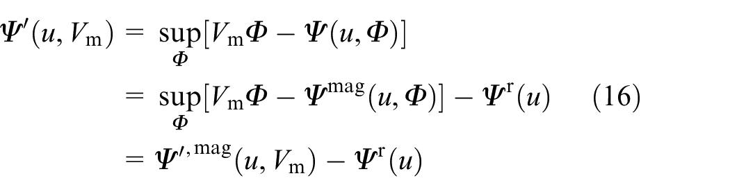
instead of directly with the Helmholtz free energy
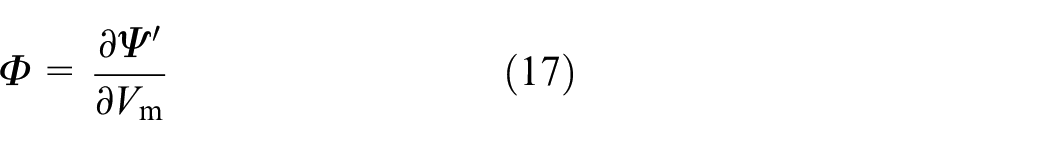
and
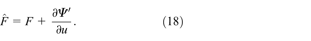
In particular, below the relation
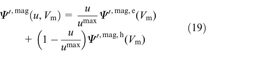
will be used for the magnetic contribution of the co-energy, where it is assumed that both,
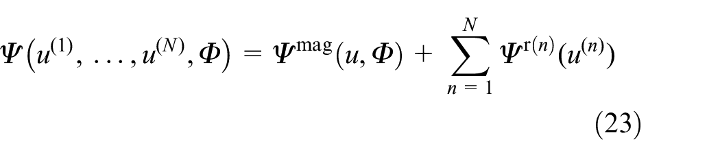
2.8. Summary
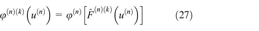
Assuming that appropriate forms for
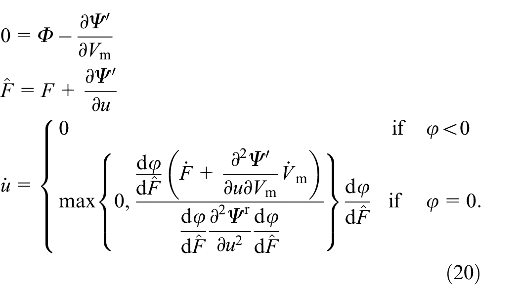
It is remarked that the last equation describing the evolution of
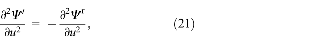
which follows from (16) and the specific form (19) assumed for the magnetic contribution of the co-energy. When using the set of equations (20), it is generally assumed that the prescribed force
2.9. Model extension
The model described above is unable to accurately describe minor hysteresis loops. In order to remedy this issue, an extension similar to the Mróz model known from plasticity (Mróz, 1967) is proposed. In particular, the presence of
In this equation
is assumed, where
is introduced again, with
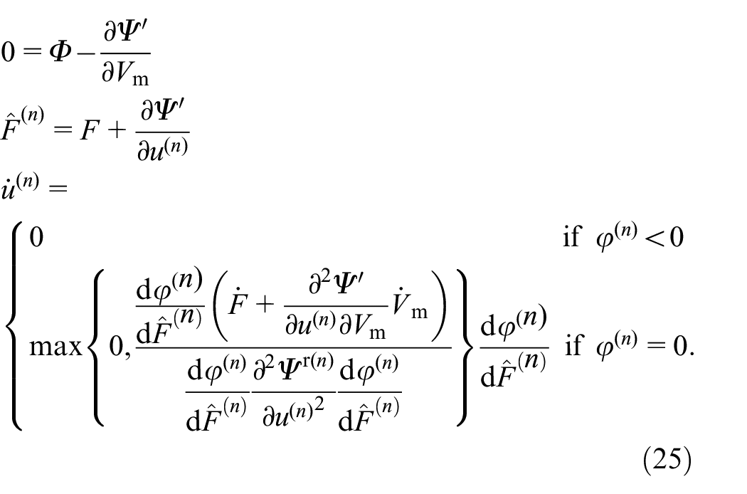
As before, it is assumed that the prescribed loading at time
3. Temporal discretization and implementation
As the set of equations (25) can usually not be solved analytically, temporal discretization is necessary. In this context, it is assumed that the loading in terms of
The backward Euler method is used for temporal discretization. In particular, let
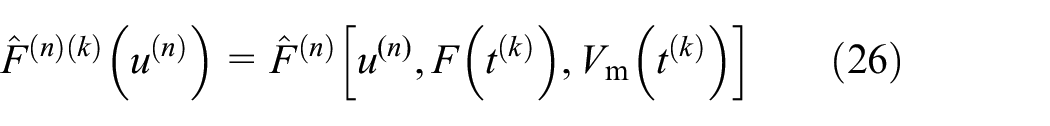
and
be the time-discrete driving forces for reorientation and time-discrete reorientation functions, respectively. Then, the equations
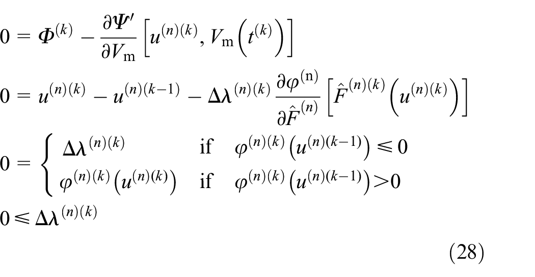
are used to obtain updated values
The practical implementation is straightforward and has been done using the free mathematical software GNU Octave (Eaton et al., 2020). A classical return mapping algorithm was used, which is a standard method for classical plasticity (Simo and Hughes, 2006) and has as well been utilized for MSM constitutive models (Kiefer et al., 2012). In particular, each time step is started with a “trial step,” which involves evaluation of
4. Identification of unknown functions and parameters
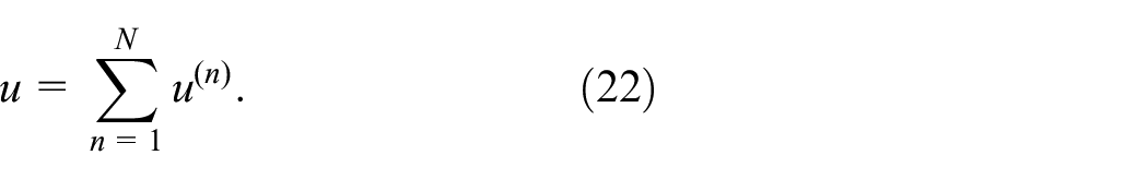
For a given number of reorientation systems
4.1. Magnetic energy contribution
In order to obtain specific forms of
With (16), (17), and the specific form of
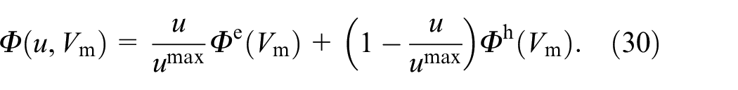
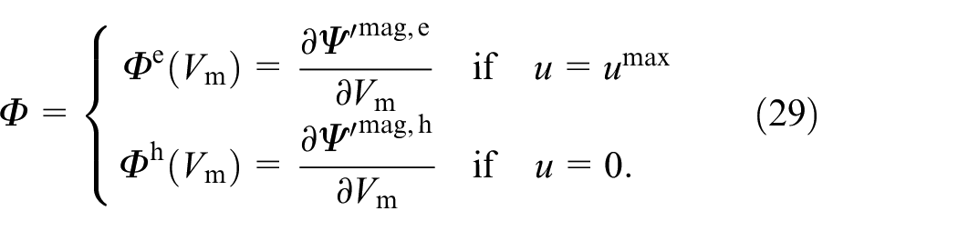
Starting from (29),
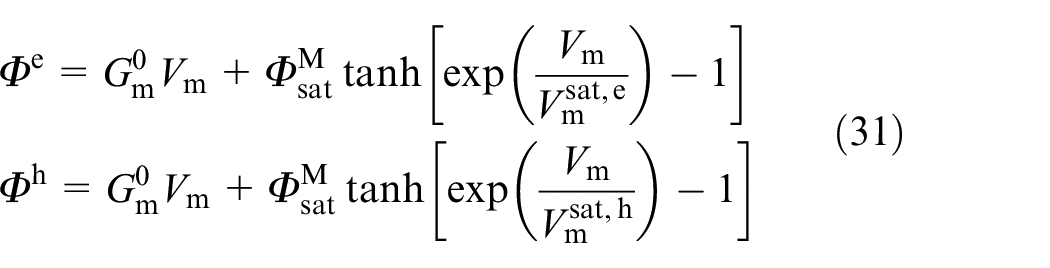
are assumed, with
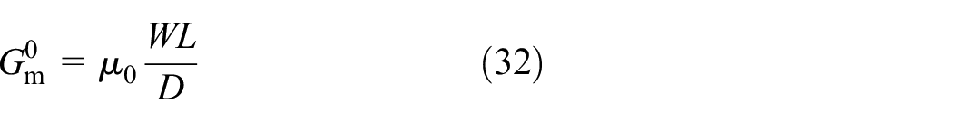
the free space magnetic permeance of the entire air gap, where

and is described for
It is noted that the proposed functions in (31) appear to be not elementary integrable and consequently,
4.2. Hardening terms
In order to restrict the admissible reorientation displacements
must be such that
where it is assumed that the parameter
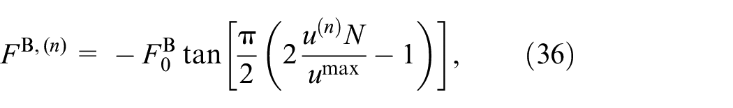
4.3. Reorientation functions
Since each reorientation function
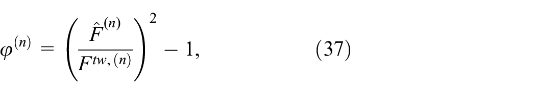
where the (positive) “twining force”
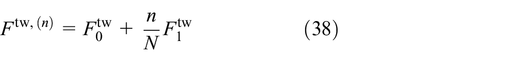
among the reorientation systems, with the new parameters
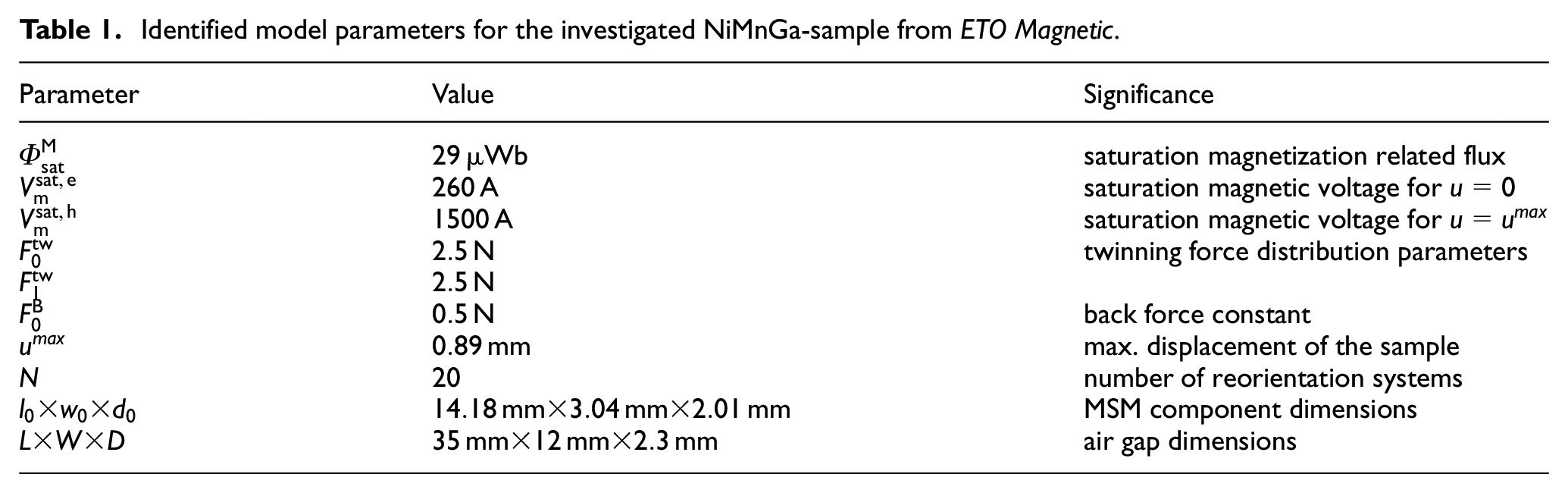
4.4. Parameter identification
Besides
Regarding the identification of the magnetic parameters, that is,
Identified model parameters for the investigated NiMnGa-sample from ETO Magnetic.
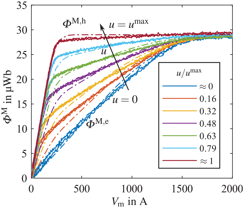
Comparison between measured (solid) and predicted (dash-dotted) magnetic curves
Regarding the remaining mechanical model parameters, mechanical first order reversal curves (FORC) were used. Advantageously, this would be done at zero magnetic voltage (where
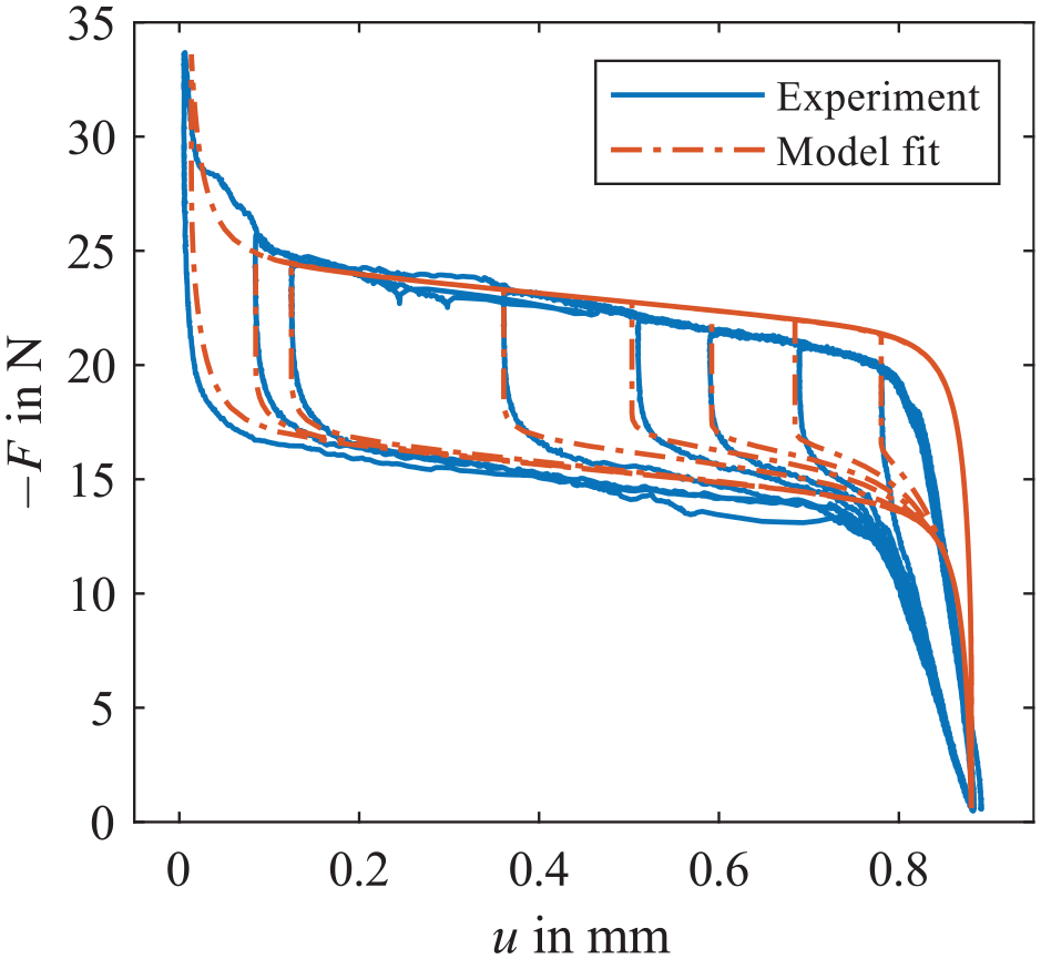
Model fit (dash-dotted) to the measured force-displacement curve (solid) at magnetic saturation. Parameters are listed in Table 1.
5. Experimental Validation
In this section, a selection of model predictions is compared to experimental results, obtained in the magneto-mechanical test bench described in Ehle et al. (2020). The measured magnetization-related magnetic flux through the MSM component was full-scale adjusted from a reference measurement with a Nickel sample and corrected for drift if necessary. In most of the following figures, measured data were slightly smoothed in order to facilitate distinction between individual curves. Displacement data have further been adjusted for elastic contributions, arising mostly from the compliance of test rig and load cell. In order to compare results from a defined initial state, the experimentally performed mechanical resetting cycle with a high compressive mechanical load prior to each experiment were considered in all simulations. After the resetting cycle, the displacement
5.1. Constant force loading experiments
In this load case, the component is magnetically loaded and subsequently unloaded by means of a sinusoidal magnetic voltage while the applied compressive loading force is held constant. The resulting curves, also referred to as “butterfly curves,” indicate the attainable displacement at a certain preload depending on the magnitude of the magnetic input. Figure 4 compares six different large-signal loops over the practically relevant loading range. For clarity, all curves are shown for positive
Comparison between measured (solid) and simulated (dash-dotted) magneto-mechanical (a and c) and magnetic (b and d) large-signal behavior at constant force for six different mechanical preloads. For the sake of clarity, rising and falling branches are plotted separately.
Two exemplary cases of small-signal behavior prediction are further discussed in the following. It is remarked that, due to the steepness of the hysteresis, even slight deviations of the model prediction from the measured curves lead to a different state at load reversal of
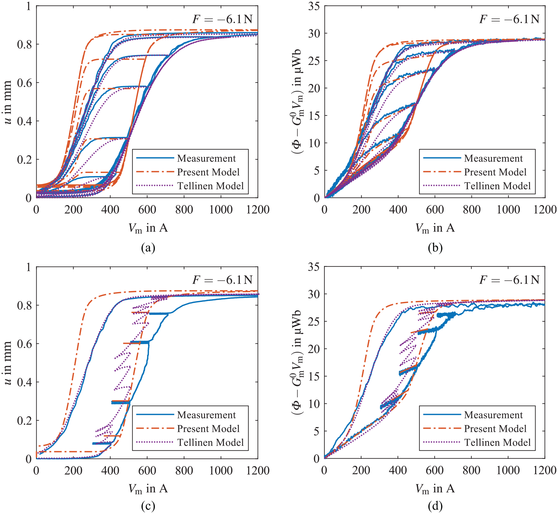
Comparison between the measured (solid) and simulated (dash-dotted) behavior at constant force loading: magneto-mechanical inner hysteresis loops and corresponding magnetic response (a and b) and small signal behavior (c and d).
The prediction of the small-signal behavior, where
5.2. Constant magnetic loading experiments
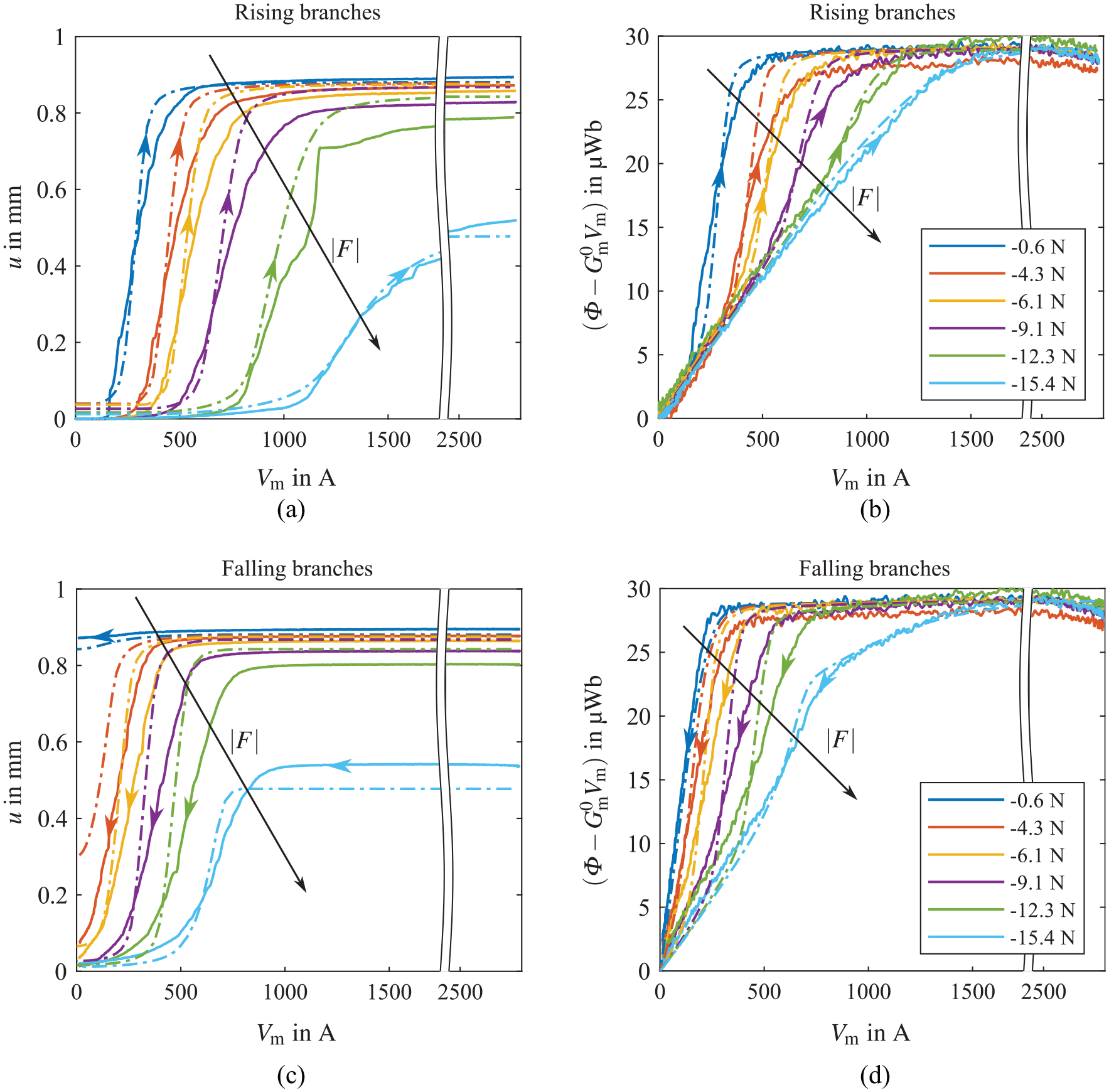
In this loading case, a mechanical compression test with subsequent unloading is performed at constant
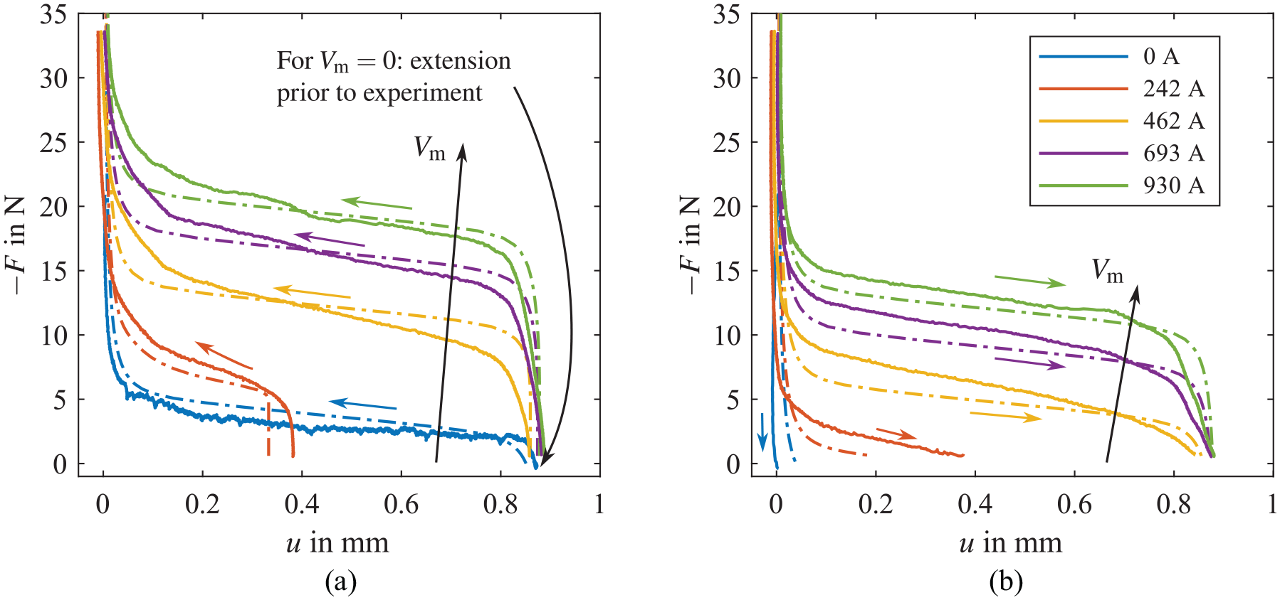
Comparison between the measured (solid) and simulated (dash-dotted) force-displacement curves at constant magnetic voltage: rising branches (a) and falling branches (b). Measured force data were slightly smoothed for clarity.
5.3. Combined magneto-mechanical loading
The prediction of the response to a combined magneto-mechanical loading cycle is depicted in Figure 7. Here, a bipolar sinusoidal magnetic voltage of increasing magnitude was applied to the MSM unit while the compressive loading force was increased linearly with time, as visible from Figure 7(a). As before, good agreement between model and experiment is achieved, although some quantitative deviations in the displacement response are observed.
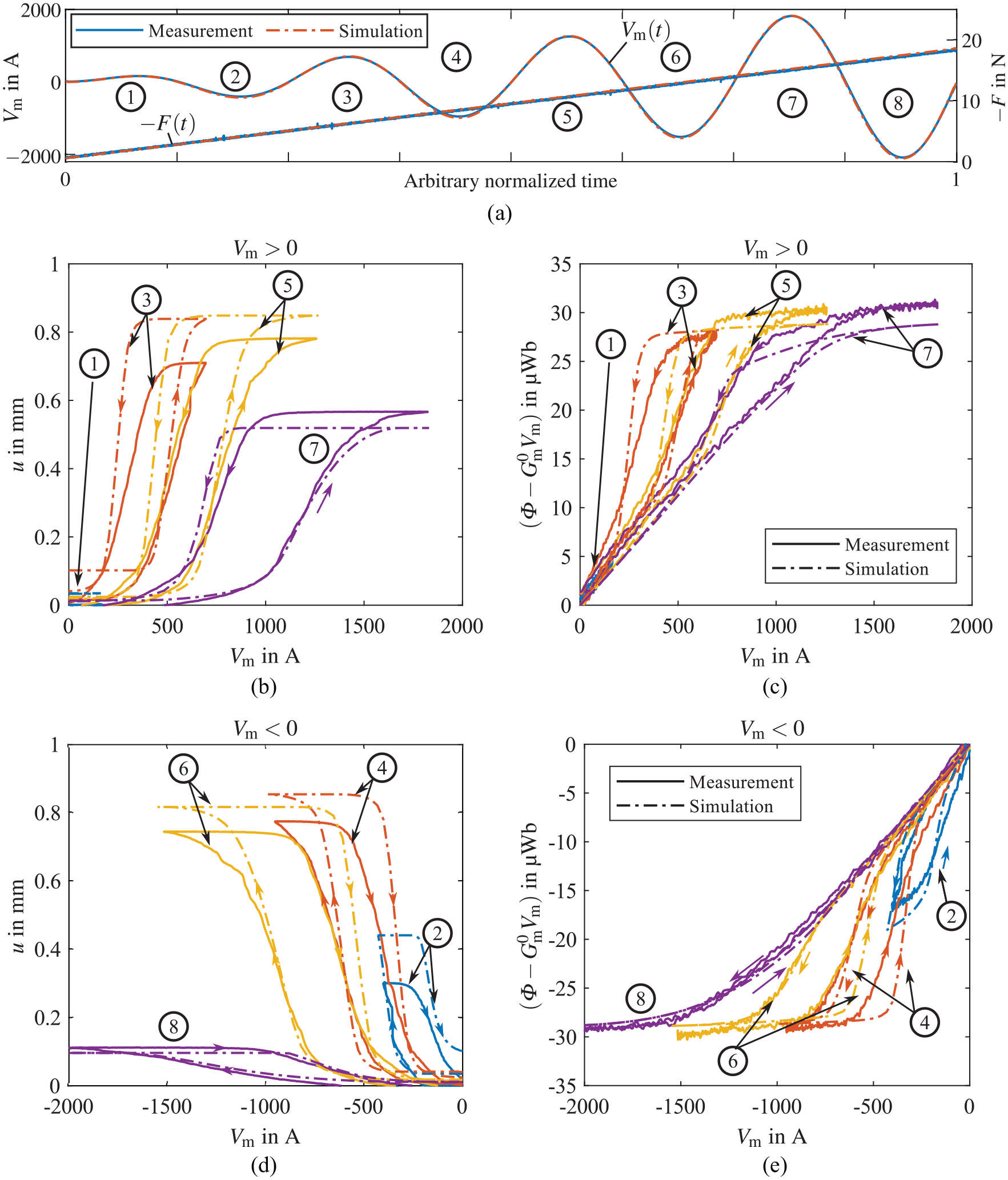
Comparison between the measured and simulated magneto-mechanical and magnetic behavior at combined loading: input signals w.r.t. time (a), magneto-mechanical response (b and d), and magnetic (c and e) response. For a better monochrome curve distinction, each of the eight half-wave cycles is enumerated and indicated in (b–e).
6. Discussion
With the chosen, simple forms of
Quantitatively, magnetic and magneto-mechanical large-signal loops are predicted with reasonable accuracy for practically relevant loads. For certain loading ranges, the agreement is only moderate, for example, for butterfly curves or compressive tests. The deliberate choice of simple constitutive functions currently limits the adaptability to the behavior of the MSM unit. It is believed that more sophisticated forms for
The model in its current form cannot account for certain effects observable experimentally. This concerns in particular the difference in hardening behavior between the two single variant states, that is, the different shape of the hysteresis as
Inherent to the chosen approach of considering the magnetic behavior of the MSM unit, the model validity is limited to the particular magnetic setup used for parameter identification. For other setups fulfilling the conditions
Despite the mentioned limitations and losing the claim of generality, the presented LEM can support system design. Its main strength is the ability to predict both magnetic and magneto-mechanical large-signal and small-signal behavior correctly, while maintaining thermodynamic consistency. Due to the strong influence of experimental conditions like friction on shape and curvature of the coupling curves, a thermodynamically correct model behavior appears to be more valuable than an exact prediction of large-signal loops, for which other models might be suited better. With its capabilities, the presented model is not only suited for the model-based investigation of actuators, but also for other applications like self-sensing actuators or generators where a correct minor loop prediction is mandatory and where the retroaction of the MSM component on the system level is function-determining. Moreover, proper efficiency and performance evaluations are possible, considering the entire system from electrical excitation to driven mechanics.
7. Conclusions
A novel, thermodynamically consistent approach for the lumped-element modeling of MSM components has been presented. By comparison with experimental data, a qualitatively good agreement was observed, while the quantitative prediction is sufficient for rough actuator design. From the results, it is concluded that the presented approach is able to account for the underlying coupling effects in MSM-based actuator systems. An asset of the model is that it is parameterized with a few comprehensible model parameters and identified with only one set of mechanical FORC and magnetic curves of the single variant states.
Future work may focus on the following aspects. An appropriate way to parameterize the model for arbitrary magnetic cores needs to be identified. Currently, due to the deliberate choice of component-related quantities, this is not envisaged. However, this might be feasible in principle if geometrically similar setups are considered. A Finite Element Analysis based parameter identification, which is the state of the art for parameterizing lumped-element models of electromagnetic actuators, might be considered. In this regard, a data conversion to account for arbitrary sample sizes would also be desirable. In addition, the origin of the experimental effects described in Section 6 should be clarified.
Footnotes
Appendix A: Model-based magnetic curve identification
In order to improve resolution and robustness in the measurement of
The magnetic permeance of (2) can approximately be computed from its geometry using
By applying Gauss’s law for magnetism to the present case,
A full-scale adjustment of
In a superordinate system model, however, it is mandatory to consider the core size properly in order to account for inductance and back electromotive force correctly.
Appendix B: Used Tellinen model formulation
For the exemplary comparison of minor loop prediction shown in Figure 5, the univariate Tellinen hysteresis model (Tellinen, 1998) has been considered. Originally introduced to model the scalar magnetic hysteresis, it was modified here to predict the rate-independent magneto-mechanical hysteresis for the load case
The scaling factors
are computed from the two so-called limiting hysteresis curves
The model was implemented in GNU Octave. For a given initial state
Declaration of conflicting interests
The authors declared no potential conflicts of interest with respect to the research, authorship, and/or publication of this article.
Funding
The authors disclosed receipt of the following financial support for the research, authorship, and/or publication of this article: The work has been supported by “Deutsche Forschungsgemeinschaft” (DFG) under Grant No. NE 1836/1-1.