
Abstract
This paper introduces a new design concept for morphing aircraft skins which combines three key design principles to create compliance-based morphing structures that are capable of large morphing deformations. These skins take advantage of additive manufacturing methods and thermoplastic elastomers of different stiffnesses to allow for strategic placement of stiffness and compliance, taking advantage of geometric anisotropy and design scaling laws to create better compromises between the need for low in-plane stiffness to reduce actuation energy and high out-of-plane stiffness to resist aerodynamic loads. The three design principles are first introduced, after which design possibilities for a family of different morphing components based on these principles are explored. Initial prototypes are shown, and a range of considerations related to manufacturing, design, and integration are discussed. Finally a multiobjective design optimization study using low fidelity models of the skin structures shows some of the potential advantages of this approach.
Introduction
The aviation community is becoming increasingly aware of its environmental impact as the sustained high level of growth it has experienced in recent decades is directly at odds with global and regional mandates to reduce greenhouse gas emissions. This has led to significant investment in new technologies for aircraft which can reduce their fuel burn through reduced mass, improved aerodynamics, higher propulsion efficiency, and more efficient operations. One promising approach to improving aerodynamic performance which is garnering increasing interest is the use of shape adaptive, or morphing, structures to change the geometry of aircraft (mainly, but not exclusively, their wings) in real time to decrease drag, improve lift generation, or both. This field of research is growing, with a large number of proposed concepts having reached different stages of analysis and technology development, as summarized well in the excellent review papers available on the subject (Barbarino et al., 2011a; Sun et al., 2016; Weisshaar, 2013) These technologies have been proposed for fixed wing commercial and military aircraft, helicopters, tilt rotors, and wind turbines at scales from ~1 m span Unmanned Aerial Systems (UAVs) (Gamboa et al., 2007) to >100 m blades for a 12-MW wind turbine (Winters and Saunders, 2018). A wide range of different types of geometry morphing have been proposed as well, including camber, thickness, sweep, span, and twist morphing. Other forms of shape change which are not wing/blade focused, such as morphing nacelle inlets (Ozdemir et al., 2015), or air intakes (Daynes and Weaver, 2013), have also been proposed. Many of the more recently introduced concepts are based on the principle of compliance, wherein the desired changes in shape are achieved through structural and material flexibility as opposed to mechanical motion of rigid components. The primary benefits of this are a reduction in complexity and number of parts when compared to mechanism-based approaches, and the ability to achieve smoother, more continuous changes in shape with lower frictional losses.
One key aspect of most compliance-based approaches to morphing is the need to have a deformable aerodynamic skin surface which is subject to competing design constraints that typically force compromise in the design process. Such morphing skins need to be able to deform significantly, with changes in length on the order of 5%–130% (Bubert et al., 2010), depending on the concept pursued, while also needing to maintain the desired airfoil shape under significant aerodynamic loads, as illustrated in Figure 1. Furthermore, the large morphing deformations need to be achieved at reasonable levels of actuation force and energy to keep the costs of the shape change from outweighing the performance benefits. It is imperative to keep the morphing system weight low, and additionally the materials chosen must provide sufficient fatigue life and resistance to environmental exposure to give a good service life. Due to the magnitude of this challenge, morphing skins have long been a central focus of the morphing community, as highlighted in the review paper by Thill et al. (2008). It could be argued that while many concepts have been proposed, none have yet been demonstrated to be able to adequately balance the stringent and competing design constraints of morphing skins, while also being robust and commercially viable. The lack of a truly suitable morphing skin solution is therefore a significant impediment to the adoption of morphing technologies into real world applications.
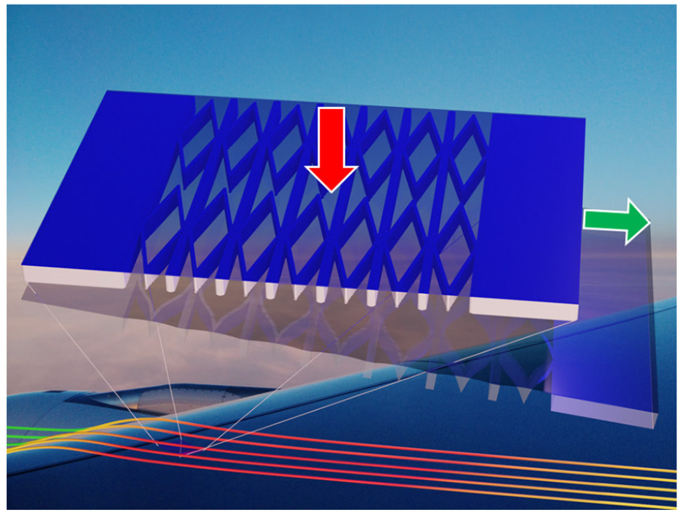
The competing requirements for morphing skins: high out-of-plane-stiffness to resist aerodynamic loads and low in-plane stiffness to minimize actuation energy.
In order to address this problem, this work seeks to introduce a new design paradigm that provides a robust, scalable, optimizable, and easily manufacturable approach to morphing skin structures. These Geometrically Anisotropic ThermOplastic Rubber (GATOR) skins provide a flexible and tough approach that opens up the design space for morphing skins, and has the potential to provide a significant advantage over other approaches due to the unique combination of three key design principles, established here:
GATOR skin design principles:
Use of thermoplastic elastomers that can be 3D printed into complex geometries
Use of multiple nozzle 3D printers to combine different stiffnesses of material into a single component, with localized stiff and flexible features
Exploitation of geometrical anisotropy and structural scaling laws to help decouple morphing skin design constraints.
Taken together, these three design principles allow for the creation of skin structures which can achieve large morphing deformations with low energy requirements and good resistance to aerodynamic loading by taking advantage of multimaterial 3D printing technology to put the right stiffness of material in the right location.
Before discussing this design concept in more detail, we will first consider the design challenge underlying morphing skins by briefly considering the existing literature on morphing skins. This will highlight the progress made to date and will help identify limitations in previous work. These limitations will motivate the new approach proposed here. The potential benefits of applying the three proposed design principles will then be explored for four different morphing skin components: skin sheets, cores, skin panels, and wing sections. Design schematics and initial prototypes will be shown in parallel to reinforce the discussion and to show the promise of the proposed approach. Finally, a low fidelity, multiobjective structural optimization study is undertaken to better understand the design tradeoffs and to highlight the achievable performance of GATOR skins.
Background: Morphing skins
From consideration of the existing body of literature, morphing skins can be grouped into two classes based on how they deform—bending dominated and extension dominated. Bending dominated skins appear on morphing concepts that require predominantly out-of-plane motion of the skin to achieve the desired shape change. The skin is not expected to get significantly longer or shorter, so the required material strains can be kept low, allowing them to be made from fairly traditional metallic or composite materials. A number of examples of concepts based on this approach exist, including the NASA Mission Adaptive Wing (Gilbert, 1981) which was flight tested on an F-111 in the 1990s, the “belt-rib” concept proposed by Campanile and Hanselka (1998) (and other continuous skin concepts such as the DLR droop nose (Kintscher et al., 2010)) and a large number of bending-based concepts which use a slit skin to allow for a change in skin length in a discrete fashion such as in Kota et al. (2009) and Previtali and Ermanni (2012).
On the other hand, extension dominated skins are designed to be directly strained in one or more of their in-plane dimensions. Achieving large deformations with extension dominated skins implies large direct material strains, which has a significant impact on the types of materials and geometries that can be used, and on the resulting stiffness properties of the skin. The advantage of extension dominated skins though is that they are applicable to a much wider range of morphing concepts. This is because bending dominated skins are only able to change the curvature (and distribution of curvature) of a component, while extension dominated skins can vary locally the length and area of a component, and significantly more complex changes in wing shape can be built up through local length/area changes. Bending dominated skins have for the most part been limited to camber and droop nose morphing concepts, while extension dominated skins have been used for camber, chord, sweep, and span morphing, with the large achievable strains allowing for wetted area changes of up to 100%. For this reason, this paper will focus on the application of the proposed design principles for extension-dominated skins. A brief review of previous work on extension-dominated morphing skins is therefore useful here.
Extension dominated morphing skins
There has been a significant amount of research into extension dominated skin concepts within the morphing community, as many researchers have sought a viable solution to creating large changes in airfoil or wing shape while maintaining structural soundness. The work to date can be grouped into three partially overlapping areas—elastomeric membrane skins, deformable core structures, and corrugated skin concepts.
The most basic approach to creating a deformable replacement for a rigid aircraft skin is to substitute the stiff aluminum or composite materials in the rigid skin panels of typical aircraft with stretchable materials such as elastomers. Indeed, silicone rubbers and thermoplastic polyurethanes (TPU; Reppel and Weinberg, 2018) when used as morphing skin membranes can offer deformations of more than 100% (Barbarino et al., 2011b; Lachenal et al., 2013) without failure. The relatively low in-plane stiffness of these materials allows for large deformations with moderate actuation energy requirements, but only if the membrane thickness is kept low. As a result, it can be difficult to create sufficient out-of-plane stiffness with pure elastomer skin sheets. Pre-tension can be used to increase the out-of-plane stiffness (Barbarino et al., 2011b; Bubert et al., 2010; Dayyani et al., 2015a), but not without cost as pre-tension forces, if not balanced, will directly increase the actuation forces.
Researchers have also considered fiber reinforced versions of elastomeric skin sheets, which in keeping with the naming conventions of composites, will be referred to as elastomeric matrix composites (EMCs). Typically this is done by adding fibers in a single direction to create a matrix-dominated morphing direction and a fiber-dominated direction (see Figure 2) that is not meant to stretch, as in Murray et al. (2010), Bubert et al. (2010), and Vocke et al. (2011). The fiber reinforcement creates a highly orthotropic material, and effectively eliminates the Poisson’s ratio induced necking-in seen in neat elastomers under large deformations. Despite the significantly increased in-plane stiffness in the non-morphing direction, the skin remains matrix dominated in the morphing direction, and so it can be difficult still to achieve sufficient out-of-plane stiffness.
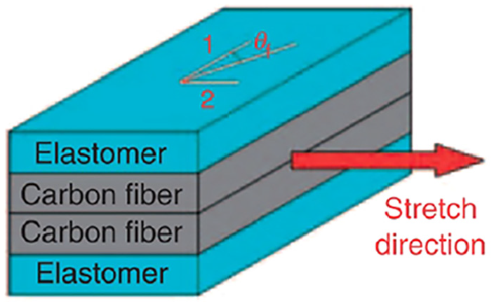
Fiber reinforced membrane (Bubert et al., 2010).
One common approach to providing better out-of-plane performance is the use of a cellular core. The basic unit cell shape of these cores (e.g. hexagonal honeycomb) has a major impact on the mechanical properties of the core, with a wide range of properties being achievable, including negative and zero Poisson’s ratios. If designed with thin features, these cores are also capable of achieving very large global deformations (over 100% (Bubert et al., 2010; Vocke et al., 2011)), making them well suited to use with elastomeric skin sheets. Cellular cores can improve performance in two primary ways, through the creation of a sandwich structure with elastomeric face sheets (thereby increasing bending rigidity) and through the intermittent support they provide the skin sheets, which reduces the unsupported length of the face sheets—effectively decreasing out-of-plane deformations under load. Olympio and Gandhi (2007) proposed an accordion unit cell core that, due to it’s geometry, displays zero Poisson’s ratio. Working separately and at the same time, Kothera et al. (2007) developed and patented a similar zero Poisson’s ratio core known as “MorphCore,” which uses a chevron shaped unit cell (see Figure 3) to achieve a zero Poisson’s ratio. Cellular cores of varying geometries have been used in conjunction with elastomeric skins for a wide range of proposed morphing applications, including span extension (Vocke et al., 2011), chord extension (Barbarino et al., 2011b), camber change (Pankonien and Inman, 2014), and even morphing engine nacelles (Ozdemir et al., 2015). Increases in length and area of 100% have been experimentally demonstrated, matching well with the elastomeric skins used to cover them.
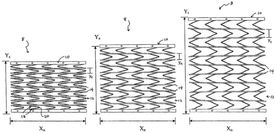
MorphCore zero Poisson’s ratio cellular core structure for morphing skins (Kothera et al., 2007).
Corrugated structures have also been extensively explored as potential morphing skins. Corrugations allow for moderately large in-plane global deformations through elastic bending along the curved (or angled) path of the corrugation. They also benefit from highly orthotropic behavior, as the corrugations provide high in-plane and out-of-plane stiffness in the non-morphing direction. As reviewed in Dayyani et al. (2015b), much research has focused on characterizing the mechanical response of corrugated skins, based on both analytical and finite element methods. Airoldi et al. (2017) present a finite element design study considering the achievable in-plane and out-of-plane performance of three different corrugation configurations, and showed that in-plane morphing extensions of over 20% are achievable without material failure. The configuration of the corrugations means that the in-plane and out-of-plane stiffnesses in the morphing direction are intrinsically coupled, and it can therefore be difficult to achieve good out-of-plane properties. To help address this, Previtali et al. (2016) suggested a double corrugated skin concept where multiple staggered bending units are bonded together to effectively form a compliant four bar linkage unit cell with much higher bending stiffness. Another issue with corrugations is that the external surface is far from ideal aerodynamically, with spanwise corrugations (as you might see on a span morphing concept) being preferable to chordwise corrugations (e.g. for camber morphing). Xia et al. (2014) investigated the aerodynamic performance of chordwise corrugations at low speed using CFD, and found reduced lift and increased drag, leading to significantly degraded performance. The compromised aerodynamic performance of corrugated skins has led to a number of concepts to smooth the corrugations, either by filling them in (Airoldi et al., 2017; Yokozeki et al., 2006) or covering them (Jenett et al., 2017; Previtali et al., 2016; Thill et al., 2010).
GATOR skin design principles
Review of the existing literature on morphing skins makes it clear that while many concepts have been introduced, the seemingly intractable problem of morphing skins—the need to have simultaneously high out-of-plane bending stiffness and low in-plane extensional stiffness—still fundamentally exists. In this work, a new approach is introduced which seeks to “engineer out” this design challenge by introducing a coordinated design philosophy based on three key principles which allows the bending and extensional functionalities of the morphing skin to be partially decoupled, such that they can be designed and optimized separately. The three core concepts of this design solution are the use of 3D printed thermoplastic elastomers, the combination of different stiffnesses of these materials into multi-material components, and the exploitation of the geometry and manufacturing freedom of 3D printing to take advantage of structural scaling laws. These three interlinked aspects will first be discussed and motivated separately, after which a family of morphing skin concepts integrating all three will be introduced.
Thermoplastic elastomers
The first design principle in the GATOR skin concept is the use of thermoplastic elastomers. Thermoplastic elastomers are a subset of the range of materials known as elastomers, which advantageously combine the very high strain capability of elastomers with the manufacturing flexibility afforded by thermoplastic polymers. They offer a uniquely balanced option for the need to create morphing skin materials which can be easily manufactured into a wide range of complex, three-dimensional geometries while also possessing recoverable strains of over 100%, well beyond the range of what is achievable with non-elastomeric thermoplastic or thermosetting materials. Of particular interest here are Thermoplastic Polyurethane (TPU) materials, as they have been in widespread use in the consumer goods (e.g. shoe soles, inflatable rafts, sporting goods, etc.(American Chemistry Council, 2016)) and construction industries (e.g. roofing membranes, flexible tubing, architectural glass lamination (American Chemistry Council, 2016)) for decades, and they are well known for their high strain, toughness, stability, adaptability (Froude, 1987), and flame retardant properties (Drobny, 2007). This combination of properties make TPUs a promising, robust material option to consider in the context of aircraft which must operate in extreme environments.
TPUs are made from three primary components, macroglycol, di isocyanate, and a chain extender, which together form a segmented block polymer. The segmented polymer chains contain alternating rigid and flexible segments (see Figure 4). At room temperature the flexible elements can straighten out to allow the material to elastically deform while the rigid segments lock together adjacent flexible elements preventing global motion of the polymer chains. When the TPU is heated above the melting temperature the hard segments become a homogeneous viscous melt, which allows the material to flow and be processed with any number of relevant thermoplastic manufacturing methods—including molding, extrusion, and welding. The bonds can also be broken using solvents, which has the same effect as applying heat—that is once the solvent has evaporated the rigid bonds will reform and the material properties are restored. This method can be used to chemically bond two or more TPU components, by locally dissolving the material.
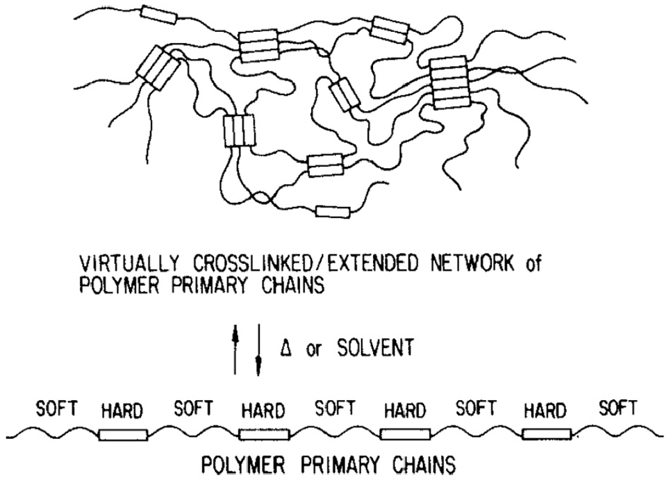
Thermoplastic urethane elastomer chain organization (Schollenberger and Dinbergs, 1978).
Because they are thermoplastic, TPUs can be 3D printed using Fused Filament Fabrication (FFF) techniques (also known as Fused Deposition Modeling—FDM) or Selective Laser Sintering (SLS). TPUs are also available as sheet stock, which can be cut, laminated, and welded as needed. Injection molding is a promising approach for higher volume manufacture, and can be used to create complex, intricate shapes to high dimensional tolerances across a wide range of sizes. Finally, because they are thermoplastic, TPUs are considerably easier to recycle than thermoset materials (elastomer or otherwise). This will become increasingly important as the aerospace industry moves toward more sustainable products. In the aerospace and wind energy industry TPUs are already in use in the form of abrasion protection coatings for metal and composite components because of their excellent wear resistance properties (Kirkegaard and Baker, 2016). They are also found in soft touch application in aircraft cabins, such as arm rests and light weight seat cushions as well as in more safety critical areas, such as cable insulation, window lamination layers and life vests. The fact that TPUs are already used in several different aerospace applications will help with the difficult process of certification for flight that faces all morphing skin concepts.
Multi-material 3D printed components
The second design principle of the GATOR skin concept is the use of different stiffness materials within a single component. This is done both at the material level (creating Elastomeric Matrix Composites) and at the component level to create hybrid structures. As is the case for traditional composite materials, using materials with different stiffnesses in morphing skins allows for the creation of highly anisotropic structures and for control over load paths. In the case of TPUs, stiffness variation is easily realized thanks to the presence of different formulations of TPU which have significantly different stiffness despite having a similar chemical makeup (Drobny, 2007). Good bonding between different formulations of TPU is readily achieved due to their chemical similarity, and there are families of such materials commercially available as 3D printing filaments (e.g. Ninjaflex and Armadillo from Ninjatek). Furthermore, TPUs can also be fused or co-bonded with other stiff polymers such as ABS and polycarbonate. Using these materials in multi-nozzle FFF printers allows for complex shapes to be created with significant control over stiffness variation, both in-plane and out-of-plane. Furthermore, both multi-nozzle printing and sheet lamination techniques allow for the creation of TPU composites, wherein the stiffer phase is used to create “fibers” which selectively reinforce the softer “matrix” phase. For components made via injection molding, the different material stiffnesses could be realized through two-stage overmoulding operations, which are becoming increasingly common in the consumer goods market. Finally, while not currently commercially available, it is easy to see how further reinforcing the stiffer TPU material with high stiffness fibers (carbon, glass, Kevlar, etc.) could lead to even more significant levels of material anisotropy and design flexibility similar to that achieved with silicone materials in Bubert et al. (2010).
Exploiting geometric anisotropy and structural scaling laws
The third key aspect of GATOR morphing skins is the exploitation of the role geometry plays in the fundamental structural scaling laws to create highly anisotropic structures with favorable bending and extensional properties. The primary scaling laws of plate-like structures tell us that where we put the material is incredibly important, but not equally important when comparing axial rigidity to bending rigidity. Bending rigidity is much more thickness sensitive than axial rigidity (thickness cubed instead of linear with thickness for a notional monolithic, isotropic plate), which means that there are performance gains to be had if we carefully choose where we put our materials. Thin, continuous skin sheets are combined with thicker cellular core structures to create sandwich panel structures with low in-plane stiffness and moderately high out-of-plane stiffness. The use of sandwich panels (be they metallic or composite) is very well known for bending dominated structures, and morphing skins are a natural extension of this approach. The selection of TPUs and the use of multiple stiffnesses within a single component marries perfectly with the exploitation of geometry. The lower stiffness “rubber-like” TPUs can be used for features requiring large strain, while stiffer “plastic-like” TPUs can be used for features which provide local reinforcement, and which don’t require high strain levels. The obvious starting point here is to use continuous sheets of the soft TPU as face sheets on either side of a stiffer TPU honeycomb core such that the face sheets create a smooth, air-tight surface while the core significantly increases the ratio of out-of-plane stiffness to in-plane stiffness. As will be explored further below, this basic approach of using geometric anisotropy can be employed in many different ways to further exploit the fundamental underlying scaling laws, and to play to the strengths of the materials being used. The selection of thermoplastic materials also significantly opens up the geometric design freedom, as 3D printing can create complex three-dimensional shapes which cannot easily be achieved with traditional honeycomb manufacturing methods. A three-nozzle printer could also be used with a dissolvable/removable support material to further remove design limitations, for example by doing away with overhang angle constraints.
GATOR skin concept embodiments
We will now consider the family of different morphing skin design concepts which are enabled by the combination of these three design principles. The proposed concepts can be subdivided into groups based on architecture and function. The most basic component is a morphing “skin sheet”—a membrane of TPU elastomer with or without additional reinforcement that is meant to provide a smooth, gapless, extensible covering for a wing surface. A second class of components can be categorized as morphing “core” structures, these are meant to provide support for the skin sheets, and need not be continuous. Indeed, cellular solids such as honeycombs or Zero Poisson’s Ratio designs such as the MorphCore concept (Kothera et al., 2007) are particularly useful in this context. Skins and cores can be combined in a variety of ways to make morphing skin “panels” which would serve in the same role as traditional wing skin panels, but with the ability to change shape. Finally, the skins and cores can be combined into a full height wing section—with a full thickness, airfoil shaped core and skin sheets as the upper and lower surfaces of the wing. These four embodiments are shown schematically in Figure 5, and there are many possible design permutations for each one that employ the three underlying design principles to different extents. Some initial explorations of this design space are presented for each of these configurations in the following sections.
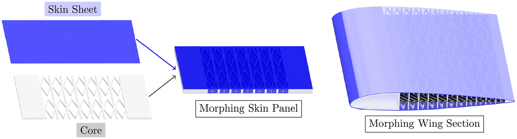
GATOR skin concept embodiments.
Morphing skin sheets
In their simplest form, GATOR skin sheets would just be thin continuous sheets of a single stiffness/formulation of TPU. These would strain directly, and so would likely require a fairly soft TPU in order to keep the actuation energy requirements reasonable. Such sheets would be able to accommodate the large strain requirements of a wide range of morphing concepts, easily achieving strains of 100% or more (Bubert et al., 2010). Skin thickness is a key design parameter, with a direct trade-off between the force and energy required to achieve a given strain and the out-of-plane bending stiffness under aerodynamic loading.
If 3D printing is used for manufacture, then another potentially useful set of design variables would be the layer height and orientation angle of the raster lines within each layer—that is the extrusion paths of the nozzle, as illustrated in Figure 6. The TPU will be essentially continuous along these raster lines, while the material properties perpendicular to the raster lines will be different to varying degrees—driven primarily by the printer settings which control how well consolidated adjacent extrusions are. Control of the material orientation at the raster level, in a manner analogous to the control of fiber angle in a traditional composite, is likely to provide beneficial properties. For example, changing raster angle layer-to-layer can be used to control the amount of anisotropy in the skin sheet, and indeed may even be a useful means for suppressing the growth of cracks in the material (McLouth et al., 2017).
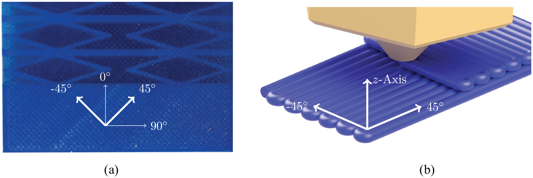
Raster lines found in 3D printed components: (a) raster lines on a morphing skin sandwich panel and (b) through thickness variation of raster lines.
If the second design principle of multi-material components is included into the skin, the design space increases considerably. In the first instance, a second, stiffer formulation of TPU can be added as “fibers” in a single direction. This will make the skin sheet highly anisotropic, with the stiffness in the fiber dominated direction being considerably higher than in the matrix dominated (morphing) direction as illustrated in Figure 7. This will allow the skin sheet to carry external pressure loads in the fiber direction while still being able to morph in the matrix direction. What’s more, the fibers will significantly reduce the effective Poisson’s Ratio in the transverse direction (
Reinforced TPU skin membrane using a stiffer formulation to act as “fibers” in the transverse direction.
Another highly beneficial design feature of multi-material morphing skin sheets is the ease with which mounting points and local reinforcements can be added. One problem common to elastomeric morphing skins is the need to attach them to the underlying structure in a robust manner, which is typically achieved through adhesive bonding. With multi-material skins, it is easy to create a smooth and mechanically robust transition from the soft TPU morphing portion of the skin to mounting tabs or reinforcement points made from the stiffer TPU. In this way adhesive bonding can be avoided entirely, and the skin sheets can be easily mounted or removed using mechanical fasteners, greatly simplifying inspection and repair. Mechanical locking features can be added to the mounting tabs, and the skin can be thickened locally to allow for countersunk fasteners, for example, to have sufficient material thickness to engage with while still being completely flush with the skin surface. Another promising attachment option is the use of heat-melt inserts—metallic threaded studs with rough external surfaces which are melted into undersized holes in thermoplastic parts, creating a high degree of mechanical locking (see Figure 8(a)). To achieve a smooth and uninterrupted surface the mechanical fasteners can be also embedded within the printed component. This can be achieved by inserting a fastener during the print (by temporally halting after the appropriate layer has been printed). This threaded insert can be inserted using either the hot melt or adhesive methods—or indeed by simply pushing it into the print as shown in Figure 8(b).
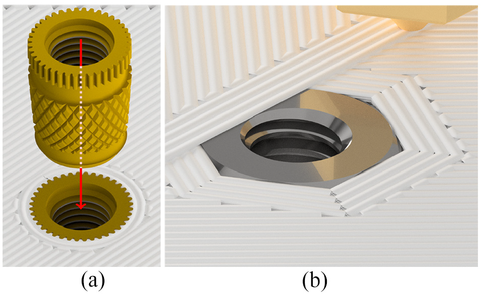
Threaded inserts in 3D printed components: (a) hot melt threaded insert installed after printing and (b) threaded inserts in 3D printed components.
Applying pre-tension to morphing skins during assembly is an effective technique for increasing their out-of-plane stiffness (Woods and Friswell, 2012). In previous work, pre-tensioning has been achieved by first stretching the skins on a mechanical rack and then bonding them while tensioned, which is awkward and requires specialized equipment. This task is made considerably easier with GATOR skins, as the skins can be printed at a reduced length with multi-material mounting tabs, and then simply stretched during assembly and bolted in place.
The performance of the skin sheets can be further enhanced if the third design principle of geometric anisotropy is used. The reinforcing fibers need not be the full thickness of the skin sheet, and their placement within the thickness can take advantage of structural scaling laws. Consider an example skin with an overall fiber volume fraction of roughly 20% of stiff TPU, as shown in Figure 9. For the cross-sections of the skin that have fiber, the fiber could be a single bundle at the center of the sheet as illustrated in Figure 9(a), or two smaller (but equivalent combined area) bundles at the extreme top and bottom of the skin (see Figure 9(b)). These two configurations would have nominally the same extensional stiffness, but significantly different bending stiffnesses. The distributed configuration takes advantage of the highly non-linear scaling of bending stiffness with distance from the neutral axis to increase the contribution to skin bending rigidity (EI) from the stiffer fibers, while still having the same extensional rigidity (EA) as the central fiber example. For a given size of morphing skin, the distributed fiber configuration would therefore have a higher bending rigidity to extensional rigidity ratio (
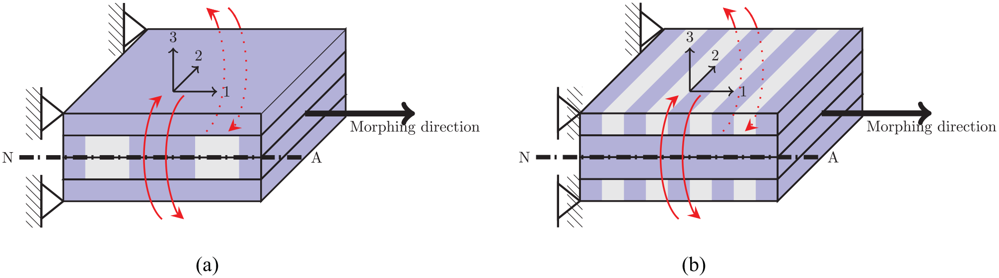
Exploiting geometric scaling within a reinforced skin sheet. Both of these concepts have the same ratio of soft to stiff material, leading to similar in-plane stiffness, but moving the stiffer phase away from the neutral axis significantly increases bending stiffness. (a) Large “bundles” of stiffer formulation (gray) on to the neutral axis resulting in a low bending stiffness and (b) smaller “bundles” of stiffer formulation (gray) away from the neutral axis resulting in a high bending stiffness.
Morphing cores
If the performance achievable with just a skin sheet is not sufficient for a given morphing application, then the skins could be further enhanced by adding a morphing core to increase the out-of-plane stiffness.
While the basic principle of using cellular cores to increase bending performance is very well known in general (Ashby, 2010), and has also been used within the context of morphing skins (Bubert et al., 2010), for example the MorphCore concept (Kothera et al., 2007), applying the three design principles of the GATOR skin concept can extend their performance considerably—both as standalone core structures and in concert with the skin concepts listed above. In traditional sandwich structures, the primary purpose of the core is to hold the face sheets far away from each other (thereby increasing their bending rigidity) while carrying the shear forces generated between them. While the core of a morphing panel will still carry shear between the face sheets, it is likely that due to the low stiffness of the skin sheets, the bending stiffness of the core itself will be a significant contributor to the overall combined bending stiffness. It will also need to undergo significantly larger in-plane deflections than a typical rigid sandwich core as it deforms with the skin sheets. The design of high bending stiffness, large in-plane deformation capable morphing cores is therefore a significantly distinct design challenge, and it is one that can be improved through application of the GATOR skin design principles.
Making cellular core structures out of thermoplastic polyurethane brings several potential manufacturing advantages. First and foremost is the ease with which complex shapes can be made. While traditional hexagonal honeycomb can be made from metallic and composite materials in large scale manufacturing processes, alternative unit cell geometries such as those typical of negative or zero Poisson’s Ratio cores (e.g. MorphCore (Kothera et al., 2007)) cannot readily be made with the standard selective bonding and expanding techniques used for honeycombs. 3D printing with TPUs (as shown in Figure 10) offers a viable production method for such cores, as does injection molding or investment casting. As is the case for the skin sheets, using thermoplastic materials also opens up a number of welding-based assembly, installation, and repair options not possible with thermosetting polymers.
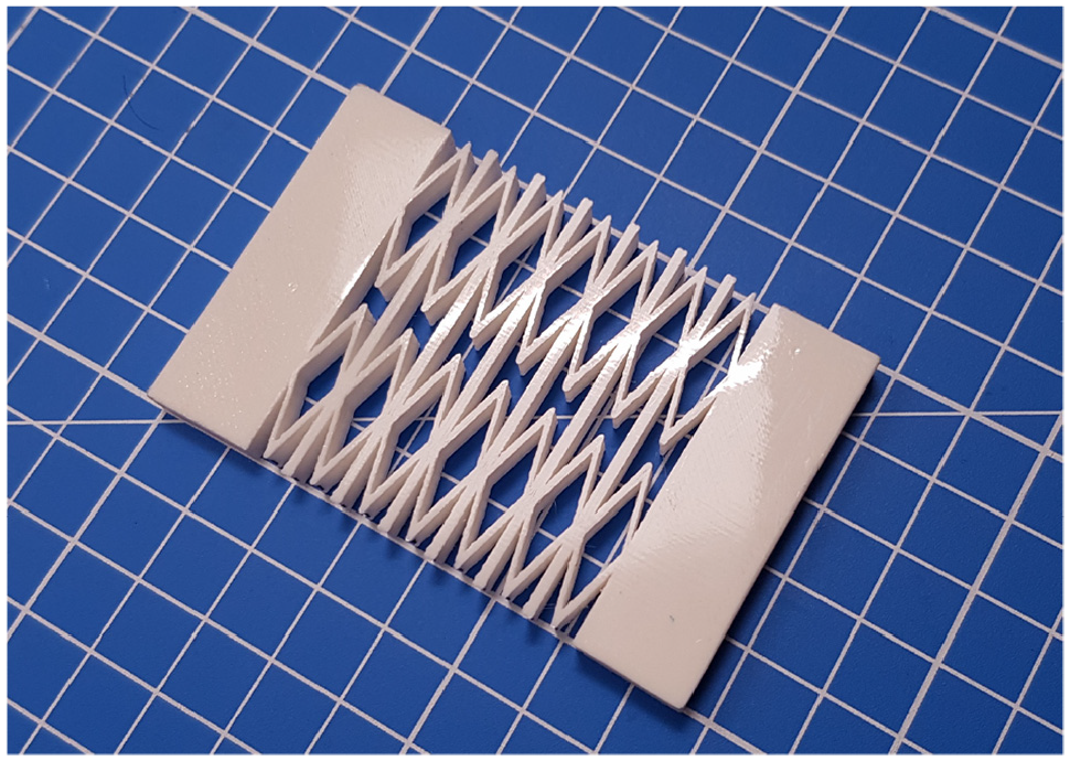
Zero Poisson’s ratio MorphCore printed from a stiff TPU (on a 1 cm grid).
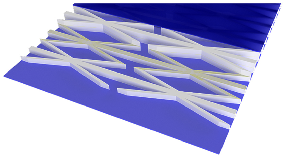
Using multiple different stiffnesses of TPU within cellular core structures allows for their properties to be improved within the context of morphing structures. Generally speaking, the ability of these core structures to achieve large morphing deformations is driven by their geometry. The repeating cellular units are made up of long, thin bending members which have high length to thickness ratios, which allow them to act like plates bending out-of-plane. In this manner, large global deformations are achieved through element bending, with low associated local strains. For example, with one particular MorphCore geometry, 30% global deformation requires 1.5% material strain (Bubert et al., 2010). Relatively stiff materials can thereby be used in the core, and the stiffer TPU compositions discussed here are a natural choice. The core does not need to be made from one single material however. In order to retain bending stiffness while lowering extensional stiffness, the softer TPU could be used in the joint regions of the core, as highlighted in Figure 11 while retaining the stiffer phase over the length of the bending members. This would create compliant hinges with more localized deformation than in typical single material morphing core structures. This would allow the bending members to be stiffer for a given overall extensional stiffness, resulting in higher shear and out-of-plane bending rigidity. In this way, using multi-material printing in the core structure will allow for considerably more design freedom in choosing the core geometry by allowing for a partial decoupling between geometry and compliance through the use of localized material compliance.
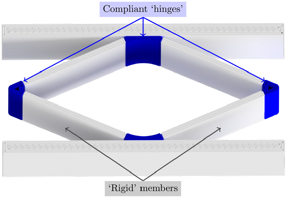
Flexible hinge concept. The compliant “hinges” are made from a softer TPU (e.g. Ninjaflex), while the “rigid” member are made from a stiffer formulation (e.g. Armadillo).
Anisotropic core geometry features such as the continuous rib members present in MorphCore also fit nicely into the GATOR skin concept, as they allow for significant out-of-plane bending stiffness along their length without significantly impeding the in-plane stiffness in the direction transverse to their length. Furthermore, these ribs contribute to the effectively zero Poisson’s ratio of the core in the morphing direction. Such features would therefore naturally be made from a stiffer TPU, and would be further enhanced with fiber reinforcement and geometric manipulation with the addition of stiffening elements.
Modifying the geometry of these morphing cores would also provide improved performance. Of course, the most basic aspect of the cellular core’s geometry—its unit cell shape and dimensions (see Figure 3)—has a large first order effect on performance. These effects are well captured by classical analysis methods for cellular solid (Ashby, 2010), and have been explored in previous morphing literature (Bubert et al., 2010; Olympio and Gandhi, 2007). It is assumed for the sake of this work that a particular unit cell geometry has already been chosen for the application, and that the basic unit cell geometry parameters have been tailored accordingly. Further geometry modification for enhanced performance can be done through both strategic addition and subtraction of material, and through careful placement of the different stiffnesses of material. For the bending elements of the core, the underlying structural mechanics implies that for a fixed cell geometry, all of the material through the thickness of the core contributes equally to its in-plane stiffness, but there is a highly non-linear contribution to the out-of-plane bending stiffness, driven by distance from the neutral axis squared. It therefore would be advantageous to strategically remove material from the center of the core. This could be achieved with various forms of cut-outs (see Figure 12(c)–(f)) or through wall thickness variation (see Figure 12(a))—leading to significant reductions in extensional rigidity with only modest impact on bending. Similarly, additional features could be added to the core to enhance bending stiffness. Flanges on the upper and lower edges of the bending members or rib members would significantly increase bending stiffness with only minimal added mass. Flanged bending members would also add to the extensional rigidity in a non-linear manner though, and so this approach would work best with the softer TPU compliant hinge concept introduced previously (see Figure 11). Flanges/stiffeners could provide other benefits as well, for example an angled flange added to the bending member would significantly increase its buckling strength and stiffness under shear loading. The use of multi-material 3D printing means that the manufacture of such core geometries is tenable, although there will of course be limitations introduced by the manufacturing process, especially if printed supports (either removable or dissolvable) are not used.
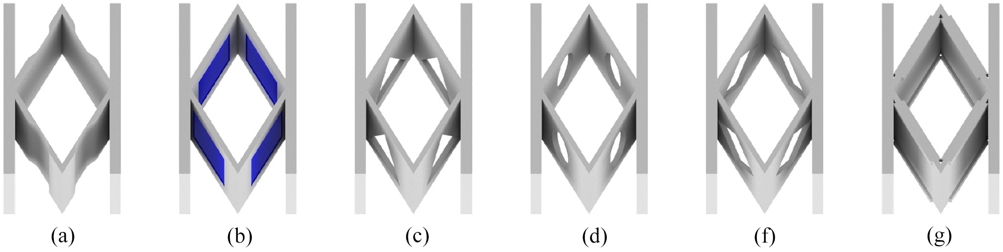
GATOR core variations: (a) the bending member is locally reduced in thickness, (b) square cut out filled with softer TPU, (c–f) triangular, circular, and diamond shaped unfilled cut outs, and (g) flanged bending members.
The structural performance of the core with respect to the key morphing skin design objectives can also be enhanced through careful placement of the different stiffness materials within the geometry. One example highlighted above is the use of the softer TPU to create localized compliant joints, but the softer phase could also be incorporated in different places through the thickness of the core as shown in Figure 12(b). Instead of the center cut-outs mentioned above, the softer TPU could be used in the center of the bending members in the same fashion, with similar options for the geometry of these inclusions. Indeed, the morphing core design premise could be entirely reversed—with the softer material being used as the primary material throughout, and the stiffer TPU only being used to reinforce the areas which will best contribute to bending rigidity.
Morphing skin panels
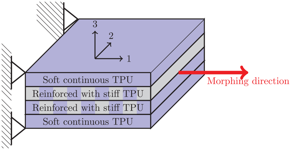
Having considered the application of the GATOR skin design principles to morphing skin sheets and morphing cores, it is useful now to further consider the combination of these two components into morphing skin panels. These panels could either be in a closed configuration of two skin sheets on the top and bottom of a core (see Figure 13) or in an open configuration with a single skin sheet attached to a core. In either case, the three design principles of the GATOR skin concept will bring benefits.
Morphing skin panel, showing layered construction.
The advantages of a thermoplastic elastomers are particularly relevant at the skin panel level, as these structures can be made from skin and core “subcomponents” that are manufactured separately. High quality bonds between the skin and core can be then achieved through thermoplastic welding operations. Alternatively, these subcomponents can be printed together to create a single consolidated part, with different material properties in different areas.
For morphing skin panels, the advantages of using multiple stiffnesses of TPU are inherently captured in the design of the skin and core sections, but there are further geometrical design permutations at the skin panel level which may be beneficial. Specifically, the thickness of both the core and the skin components can vary over the length of a skin panel. When used on an aircraft wing, both the aerodynamic and actuation loads on a GATOR skin panel will vary significantly in the spanwise and chordwise directions. This variation in loading conditions immediately motivates tailoring the properties of the panel across its width and length to better match the local loads. For example, if we consider a skin panel as a plate anchored on either end to ribs on a wing, then there would be a clear advantage to increasing the bending rigidity of the panel toward the center of the inter-rib gap to better match the bending moment distribution created by the aerodynamic pressure loads. This could be realized through variation of the core thickness across the spanwise length of the panel. Similarly, given the highly non-uniform pressure distribution along the chord of an airfoil, and the desire to minimize local out-of-plane skin deformations, it would be beneficial to have the thickness of the skin sheets increase toward the suction peak on the leading edge. In addition to simple thickness changes, the structurally advantageous geometry manipulations discussed above could also be used in a spatially varying way for the skin or core elements (see Figure 14) to tailor the stiffness distribution of a GATOR skin panel.
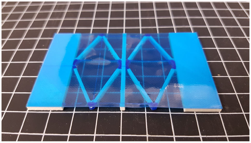
A GATOR skin panel: soft TPU skin membrane printed with stiffer TPU core and integrated compliant “hinges.”
Morphing wing sections
The final family of GATOR skin structures to consider is a variation of the skin panel in which a single “panel” makes up the entire cross-section of a wing, one example of which is shown in Figure 15. The core would therefore be in the shape of the airfoil (Figure 16(a)), and the upper and lower skin sheets would directly form the upper and lower skin surfaces of this wing section. This would create a panel of the maximum possible thickness in all locations, and would avoid the potential inefficiency of a second skin sheet on the inside face of a typical panel. This inside sheet is not needed for aerodynamic smoothness, and while it does contribute to panel bending stiffness, it also significantly affects extensional stiffness. A morphing wing section of this sort would be appropriate for many different morphing concepts including span extension, twist, dihedral/anhedral, sweep, camber change, and variable sweep. While it could indeed be the primary structural component of such a morphing wing, it is likely that additional internal structural reinforcement would be used to help carry the global loads, with the morphing wing section maintaining the airfoil shape and carrying the local pressure loads. Examples of relevant structural configurations include the span extension concept of Bubert et al. (2010) and Vocke et al. (2011) and the morphing winglet concept by Wang et al. (2017), which all include additional internal structure.
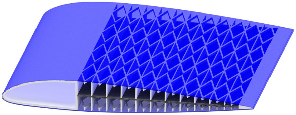
Camber morphing wing concept utilizing a zero Poisson’s ratio MorphCore printed onto a TPU skin membrane.
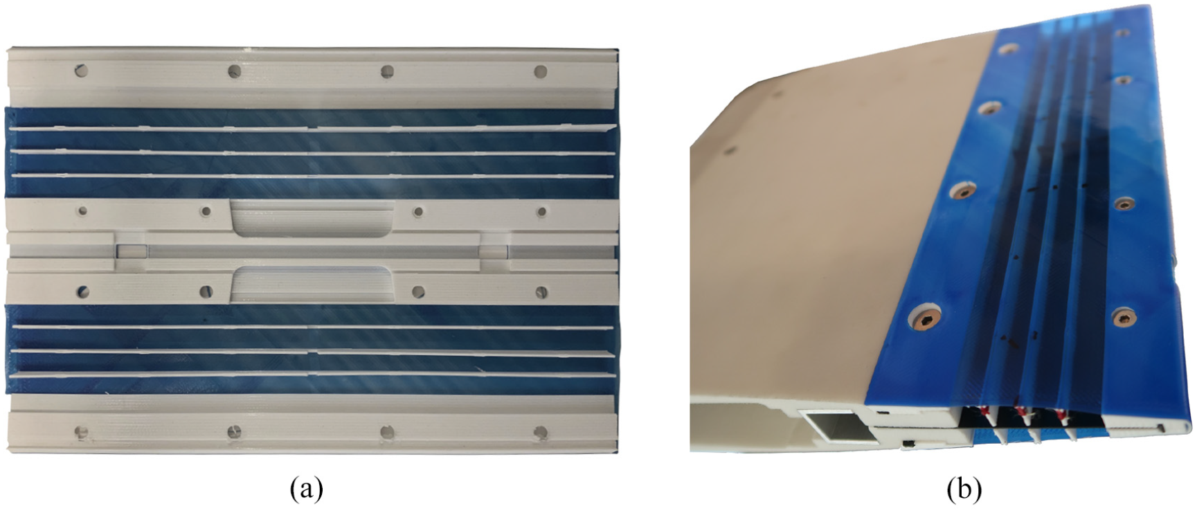
GATOR morphing skin for a FishBAC morphing trailing edge: (a) skin panel as printed—note that the upper and lower skins are printed together and (b) skin panel installed onto trailing edge.
For such a configuration, the advantages provided by the GATOR skin design principles are considerable. While many of the same design approaches used for the skins, cores, and panels are all still relevant, there are aspects particular to the full cross-section situation worth mentioning. Thermoplastic materials will again be very useful, as there would likely be a number of additionally components which need to be attached to, or integrated within, the morphing components which could take advantage of the many attachment options for TPUs, as discussed previously. Similarly, any internal support structure, actuation mechanisms, instrumentation, wiring, and ancillary components would also need to fit within the morphing airfoil section. Cut-outs in the core would therefore most certainly be present, and if designed properly they could provide this needed space while also contributing to improvements in the structural performance of the morphing airfoil by removing material in a manner which directly reduces in-plane stiffness while only modestly affecting out-of-plane stiffness. Finally, the design freedom provided by 3D printing becomes even more advantageous for full GATOR morphing wing sections due to the significant increase in geometrical complexity inherent to full wing sections with large internal cut outs.
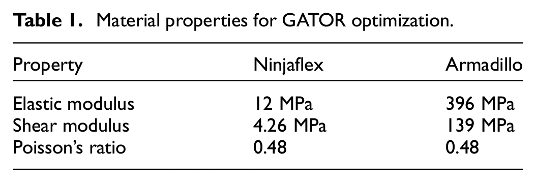
A prototype GATOR skin, seen in Figure 16, has been designed and printed for the Fish Bone Active Camber (FishBAC) morphing concept (Woods and Friswell, 2012) to highlight the advantages of the concept. This demonstrator is made from two different stiffnesses of TPU, NinjaFlex (in blue) and Armadillo (in white) that are manufactured by NinjaTek, with nominal tensile moduluses of 12 and 396 MPa respectively. The FishBAC camber morphing section makes up the rear 25% of the 270 mm chord of a NACA 23012 airfoil. The upper and lower GATOR skin panels sandwich a carbon fiber bending spine. Both panels were printed on a Lulzbot TAZ 6 FFF printer as a single piece (see Figure 16(a)) with the soft skin first being printed flat against the bed. Supporting structures made from the stiffer Armadillo TPU are then printed on top of the skin, and include stringers to maintain the airfoil thickness distribution and mounting tabs to connect the skin to the spine and the non-morphing portion of the demonstrator. Countersunk holes for mounting fasteners were printed into these tabs, and an angled mechanical locking feature is included into the tabs to provide further strength to the connections. The unsupported portions of the skin were printed 15% shorter in chordwise length than the final dimensions to allow for pre-tensioning of the skin. To install this multifunctional, single component GATOR skin the panel is first removed from the printer bed, and then the trailing edges of the upper and lower skin panels are bolted together around the carbon fiber spine (see Figure 16(b)). The forward edges of the panels are then stretched and mechanically latched on the non-morphing portion of the airfoil, after which the forward fasteners are installed to provide a quick, secure, and removable mounting of the skins. While multi-material printing with soft materials in a non-trivial process for FFF machines, once the printing specifications were sufficiently dialed in, the manufacture of this complex component was quite straightforward, and assembly is much simpler and faster than the process previously used (Woods and Friswell, 2012). The previous process required the stringers to first be individually bonded to the spine, with jigs required to maintain the proper positioning. The silicone skin sheets previously used for the skins would then be mounted onto a stretching frame to pre-tension them. The skins start out significantly longer than the actual morphing region to allow for their ends to be mechanically clamped, and to avoid interference between the stretcher and the morphing device. After this came a fiddly adhesive application process where silicone adhesive had to be applied individually to each of the stringers and to the large bonding pads at the two ends of the skin region. The adhesive starts to cure immediately, and forms a partially cured skin within several minutes that inhibits proper bonding, and so this stage must be done very quickly. With the adhesive fully applied, the stretched skin would be positioned onto the adhesive and left to cure. After curing, the stretcher was removed and the excess skin was trimmed to size. While this did result in a smooth outer surface, the skin panels were not removable for repair or access, and the process was very labor intensive. The benefits of the GATOR approach are clear in comparison, as multiple components of different materials can be printed together and stretched and installed with no external jigging or tooling, and with no adhesive. This first prototype of the GATOR skin concept only begins to explore what is achievable with the three part design philosophy proposed here, and it is already a significant improvement over previous work.
GATOR skin optimization studies
In order to more fully explore the potential benefits of the GATOR design principle, a simple design optimization study was undertaken. This study uses established analytical models of cellular cores and skin membranes to explore the range of performance achievable by the cores and by sandwich panels made from skin membranes on either side of a core. The analysis is based on a unit cell approach and simple beam theory based approaches to estimating the in-plane and out-of-plane properties of cellular solids. We will consider the performance achievable with respect to the axial rigidity EA and the bending rigidity EI, where EA will be minimized and EI maximized.
Methodology
The analysis of the cellular cores is based directly off of the work in Huang et al. (2016) and Bubert et al. (2010), both of which are extensions of the cellular solid theory developed in Gibson and Ashby (2010). Simple linear plate theory is used to derive effective in-plane and out-of-plane rigidity. These methods are not expected to be precisely accurate, especially for larger deformations, but they will capture the inherent physics of deformation in a way which helps elucidate the advantages of GATOR skin panels.
In-plane deformations of the core are assumed to come solely from bending of the angled bending members within the cellular core, as modeled with simple plate theory in Bubert et al. (2010).
where
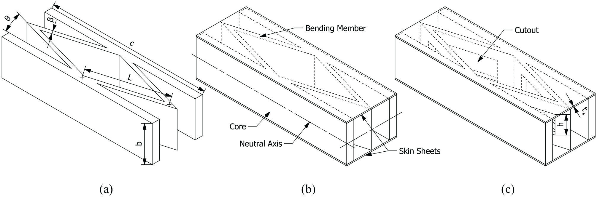
Schematic of unit cell, where (a) represents a core only, (b) a sandwich panel comprising of a MorphCore unit cell sandwiched between two skin sheets, and finally (c) which features the same setup but with a core with cutouts.
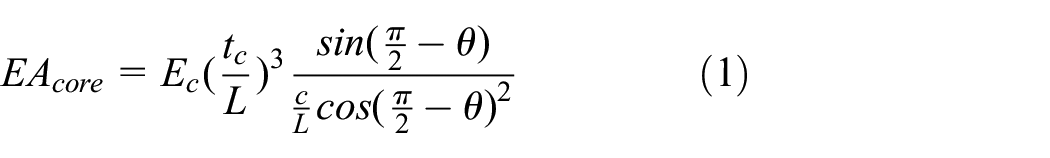
In-plane deformation of the skin membranes is estimated from simple linear elasticity. This ignores interaction effects between the core and skin membrane, but it useful for initial estimates of structures with low to moderate deformations.

where

Bending deformations of the core come from a combination of bending and torsional deformations of the angled bending members, which combine to give a total change in angle over a single unit cell, as shown in Huang et al. (2016), and solved with an applied unit bending moment, M = 1.
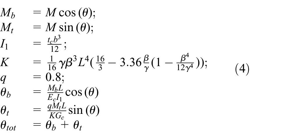
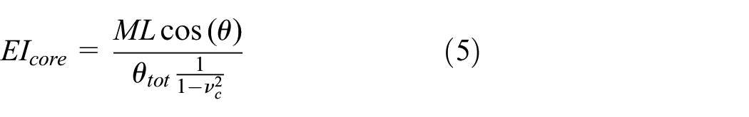
where
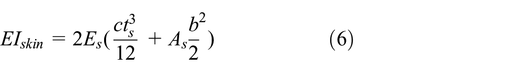
And again, linear superposition is used to find the total bending rigidity of the morphing skin sandwich panel:

Finally, one of the key concepts of the GATOR design principle is the ability to manufacture core structures with internal cut outs that are meant to give a better trade-off between EI and EA. We consider here the simplest embodiment of this idea, which is a rectangular cut out from the center of the bending members that is symmetrical about the centerline of the core, as shown in Figure 17. We again use the principle of linear superposition to estimate the in-plane and out-of-plane properties of these cores as the EI or EA of the full core minus the EI or EA of the portion cut out.

Optimization
Having established the analytical methods used to model the GATOR skin structures, we will now consider the optimization methodology. As the primary purpose of this investigation is to explore the tradeoff between the competing objectives of minimizing axial rigidity while maximizing bending rigidity, a multiobjective optimization was performed using the Matlab function “paretosearch,” which finds pareto frontiers in n-dimensional space using a direct multisearch algorithm which does not require derivatives and does not aggregate the objectives.
Four different scenarios were considered, core only, skin only, skin + core, and skin + core + cutout (where the cutout is applied to the core). For each case, a two objective optimization was performed. As the paretosearch function minimizes the values of the set objectives, the objectives used were EA and
Material properties for GATOR optimization.
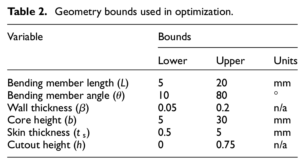
The other design variables were open to the optimizer to vary, within specified bounds chosen to ensure achievable minimum thicknesses of components. These values are shown in Table 2, where it can also be seen that the maximum height of the core has been constrained to
Geometry bounds used in optimization.
The results of the optimization for the four different skin configurations studied are shown in Figure 18. Here we see that for all of the configurations, the two objectives are competing—that is to say it is only possible to increase the bending rigidity through an increase in EA, although the shape of the Pareto frontiers are very different. We see that both of the panel configurations are able to achieve a given value of EI with a much lower EA penalty, with the addition of cutouts to the center of the core providing further significant advantage for larger values of EI. The skin only case shows an interesting behavior, with a steep initial cost in EA required to generate EI, but with a softening of the curve as EI increases. The maximum obtainable bending rigidity for the skin only case (within the 30 mm thickness constraint) is
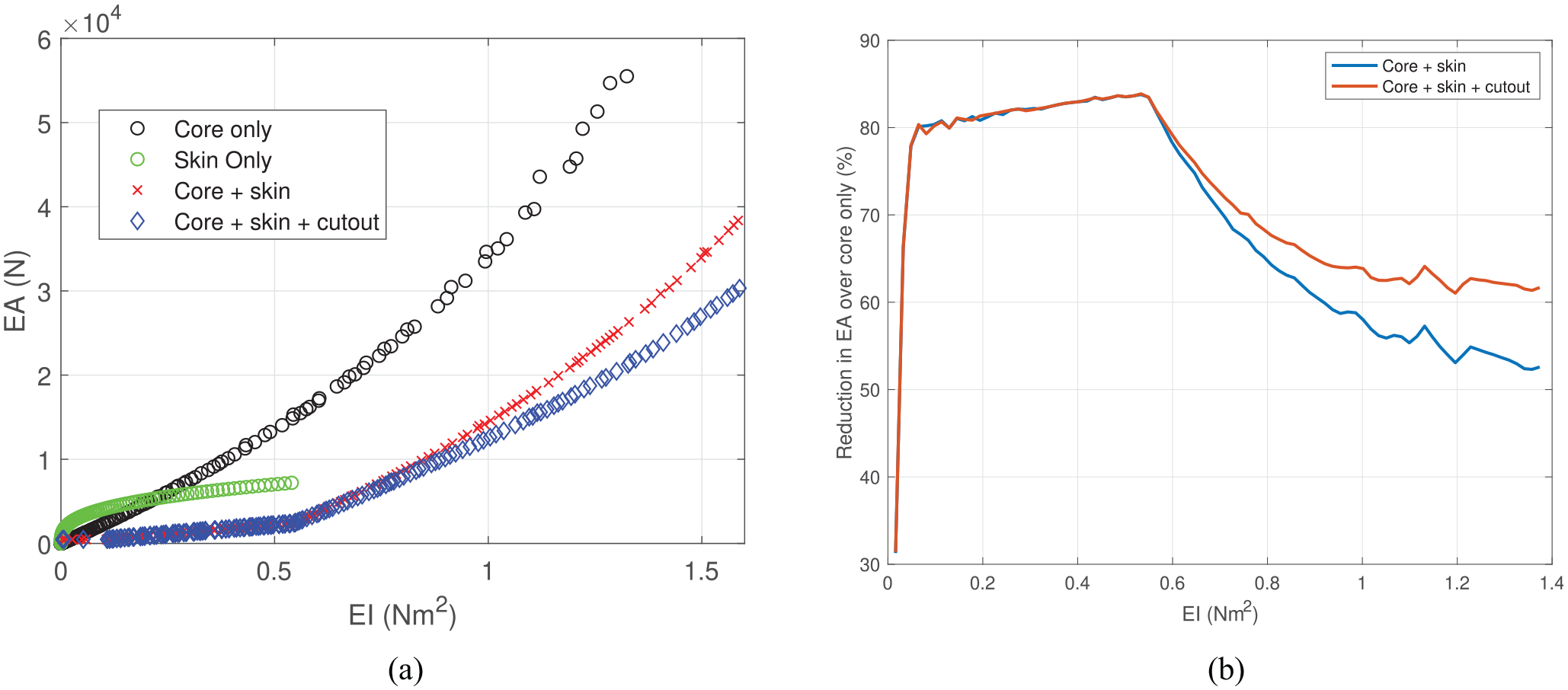
Optimization results: (a) Pareto frontiers for the different GATOR skin configurations and (b) effectiveness of sandwich panel construction.
In Figure 18(b) is shown the achievable reduction in axial rigidity at a given bending rigidity for the two sandwich panel configurations, as compared to the core only. It is here that we see just how advantageous the sandwich construction is, and how the ability to print sandwich panels based on the GATOR concept can help realize effective morphing skins.
It is also interesting to note that while the skin only and core only results show a smooth variation in the tradeoff between objectives, the presence of a skin leads to a kink in the frontiers for the sandwich panels. The location of this kink is directly driven by the upper bound on skin thickness. Before the kink, we see that the sandwich panel results have a much lower slope than the core only, implying they can increase EI with very little penalty in EA. This occurs through a balancing of the design variables and a progressive increase in skin thickness. Once the upper bound on skin thickness is hit, further increases in EI must come through wall thickness and angle changes, as the core height is also maximized very quickly with increasing EI. This changes the underlying structural efficiency of the sandwich in a way which forces a steeper slope to the frontier—indicating more compromise in the design, although it should be noted that the slope of the frontiers for the sandwich panel is always lower than that of the core only (at matched EI).
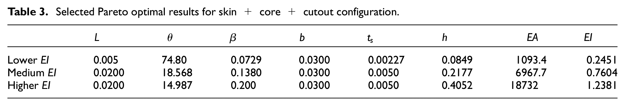
Further insight into the interplay between design variables along the Pareto frontier for the core + skin + cutout configuration can be gained from the parallel coordinates plot shown in Figure 19. This figure plots a line for each individual on the Pareto frontier that passes through the design variable values for that individual and the values of the objectives that it achieves. There are separate y-axis for each design variable and objective, and the lines are colored based on their EI values. Here several design trends can be seen. Firstly, we see how quickly the height of the core hits the upper bound with increasing EI. This result is expected since EI increases very quickly with height, and the optimizer takes advantage of this for all but the smallest values of EI. We also see that the height of the cutout at the center of the core initially increases with bending rigidity, but once the skin thickness upper bound is hit, smaller cutouts are needed in order to increase EI. A few selected results for the skin + core + cutout configuration configuration are shown in Table 3, where the three examples shown are from the lower, middle, and higher ends of the EI range respectively. Here we can see that the bending member angle steadily decreases, the wall thickness increases, the skin thickens (until hitting the upper bound) and the amount of cutout in the core also increases.
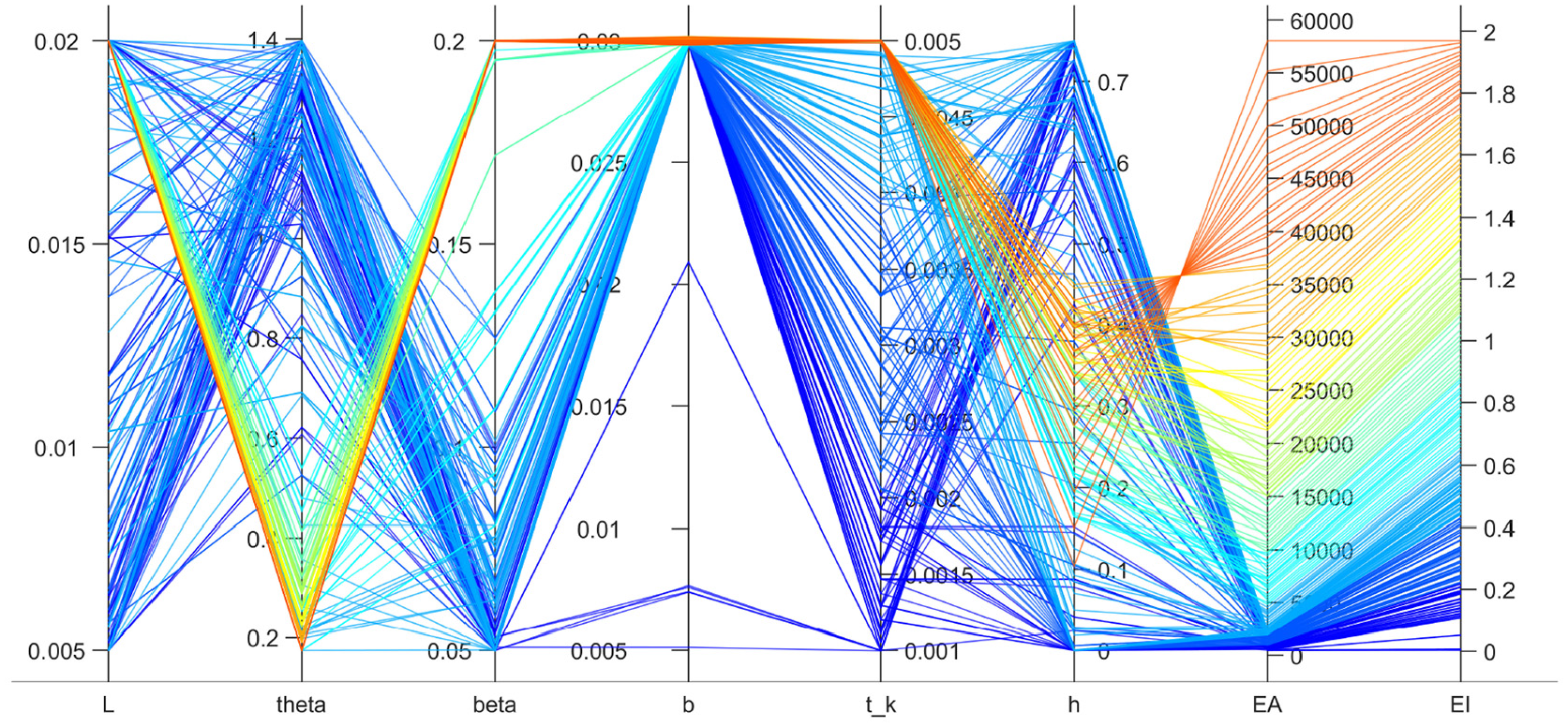
Parallel coordinates plot for core + skin + cutout configuration, showing how the individuals on the Pareto frontier map to the input variables and the two objectives. Lines colored by EI.
Selected Pareto optimal results for skin + core + cutout configuration.
This initial optimization study on GATOR skin configurations, while based on simple analytical models, is useful for highlighting the advantages of using the GATOR skin concept to create multi-material, 3D printed sandwich panels. These results consider a single flat unit cell, but the basic scaling laws at play will still be advantageous for the more complex geometries expected with real morphing skin applications, although future work will need to consider aspects such as geometric and material non-linearities, shear deformations, and morphing deformation limits using more physically rich models.
Conclusions
In this paper the GATOR morphing skin concept was introduced and defined. This new approach to designing morphing skins for aerodynamic applications is based on three design principles: (1) use of 3D printable thermoplastic elastomers such as TPU, (2) use of multiple nozzle printers to combine different stiffnesses of material into a single component, and (3) exploitation of geometric anisotropy and structural scaling laws. This approach allows for the creation of robust, scalable, and highly deformable morphing skin structures with a very high level of design freedom from a single-stage manufacturing process. GATOR skins are able to partially decouple the competing design constraints of large morphing deformations: low actuation energy requirements and high resistance to deformation under aerodynamic loading. The design principles are applicable to morphing skin sheets, morphing cores, sandwich panels, or full wing sections, with application to a wide range of morphing concepts. The following key conclusions can be drawn from this work:
Utilizing additive manufacturing methods provides a significantly increased design freedom in generating highly complex shapes which is not possible using traditional manufacturing methods. Particularly, multimaterial 3D printing allows materials with different mechanical properties to be used in the same manufacturing process. Providing a dissolvable or removable support material further increases design options.
Using TPUs that have similar chemical properties provides a very strong chemical bond between separate components, allowing for stiffness tailoring of components through the placement of stiffer materials in areas where they can effectively contribute to load carrying without unduly increasing morphing energy requirements and using softer materials in areas that maximize the deformability of the structure.
The skin’s structural properties can be further improved by strategically placing the stiffer TPU material, or additional fiber reinforcement, further away from the neutral axis to increase the ratio of bending stiffness to in-plane stiffness.
The skin and core geometries of GATOR skin panels can be locally optimized to the varying loading conditions and morphing requirements across the chord and along the span of a wing.
An initial prototype of a GATOR skin panel has been designed and built, and has shown significant improvement in the manufacturing and assembly processes of a morphing camber airfoil.
A simple design optimization study has shown that the GATOR approach can provide significantly better solutions in the EI versus EA objective space than what can be achieved with morphing cores alone, with reductions in EA of 50%–80% at matched EI conditions for the nominal aircraft skin example studied here.
The creation of effective morphing skin solutions has proven to be a significant roadblock to the implementation of many morphing concepts. The GATOR morphing skin concept provides a set of design guidelines that may help create viable solutions. Work is currently ongoing into wind tunnel testing of the concept on a morphing wing, and on detailed analysis and characterization of mechanical properties. Future work will use these analysis tools to fully explore the design space available, searching out practical designs which best balance the competing design objectives. It is also imperative that the highly non-linear behavior of the TPU materials, and their recoverable strain limits, are properly accounted for in future work.
Footnotes
Declaration of conflicting interests
The authors declared no potential conflicts of interest with respect to the research, authorship, and/or publication of this article.
Funding
The authors disclosed receipt of the following financial support for the research, authorship, and/or publication of this article: This work was supported by the Engineering and Physical Sciences Research Council (EPSRC) as part of Dr. Woods’s Early Career Fellowship, AdAPTS: Adaptive Aerostructures for Power and Transportation Sustainability (EP/T008083/1). Further funding support was also provided by the European Union’s Horizon 2020 research and innovation programme as part of the SABRE project, grant agreement number 723491 and the EPSRC Centre for Doctoral Training in Advanced Composites for Innovation and Science (grant number EP/L016028/1).