
Abstract
This article presents an experimental and numerical investigation of Mode-I fracture control in aerospace grade unidirectional laminated composites (AS4/914) using the smart material approach. The P1 type macro fiber composites (MFC) actuators are selected for current research because of their higher free strain, high mechanical flexibility, and good blocking force. The opening mode (Mode-I) interlaminar fracture tests have been carried out on DCB specimens having surface bonded MFC actuator patches under the application of electric voltage within a range of 0–1500 V. These fracture control tests have been performed on pre-cracked (PC) and non pre-cracked (NPC) double cantilever beam specimens. The modified pin force model has been adopted for the evaluation of actuation forces in surface bonded MFC actuators. The XIGA-CZM based numerical formulation is utilized for numerical fracture modeling under electromechanical loading conditions. The MFC actuators have significant control over Mode-I fracture energy under the application of peak operating voltage. The numerical model using a modified pin force model in combination with XIGA-CZM based fracture model shows a good agreement with experimental observations.
Keywords
1. Introduction
Laminated composite structures have wide applications in aerospace and naval industries due to their lightweight, high specific strength, high tailoring ability, and excellent corrosion resistance. With increasing industrial and research applications, composite structures are susceptible to several types of failures such as fiber breakage, matrix cracking, delamination, and fiber pullouts. As of these results, the delamination initiation and propagation investigations in aerospace grade laminated composite structures are found an active research area since a few decades. The service life of cracked or damaged components can be prolonged through effective damage control instead of instant replacement of the structure. Therefore, the effective control of delamination or damage propagation in aerospace structures is a critically important and practical research area for their structural integrity.
The smart materials offer numerous applications where actuators are utilized for structural response control and sensors for monitoring the structural response because of their ability to couple electrical and mechanical energy. The structures incorporated with smart materials (actuators or sensors) are known as smart or intelligent structures, which can improve the performance of engineering structures. A wide range of actuators or sensors is available in the market both at research and commercial levels. Some of these smart materials include piezoelectric actuators and sensors, shape memory alloys, electrorheological and magnetorheological fluids, and electrostrictive and magnetostrictive materials (Mackerle, 2003). Several researches have been carried out on the electromechanical characteristics of piezoelectric materials and devices (Narita et al., 2005; Shindo et al., 2004). The advanced piezoelectric materials offer active damage control techniques to suppress the damage onset and propagation in composite structures (Rogers, 1993). Theoretical studies have been carried out for crack behavior control in beam structures under mechanical loading conditions using piezoelectric actuators (patches) (Abuzaid et al., 2015; Duan et al., 2008). Shape memory alloy actuators are found one of the most practical candidates for crack propagation suppression in composite structures (Kimura et al., 2006). Recently, experimental and numerical studies have been performed to demonstrate the Mode-I delamination control using piezoelectric actuators in woven glass fabric composites under ambient and cryogenic environmental conditions (Shindo et al., 2013a, 2013b). Recently, several studies have been carried out n-situ Healing of Mode-I Fatigue Crack in Fiber Reinforced Composites (Vishe et al., 2020, 2021).
The piezopolymers are mainly used as sensors due to their low capabilities of piezoelectric actuation and the limited applications of piezoceramics leads to the development of a new category of actuators named as AFC and MFC actuators (Kerur and Ghosh, 2011a; Teter and Gawryluk, 2016). These active materials offer improved actuation capabilities with an addition of high flexibility characteristics. The actuation technology for both macro fiber composite (MFC) and active fiber composite (AFC) actuators is based on the interdigitated electronics (IDE) (Hu et al., 2020; Rimašauskienė et al., 2019; Thomas et al., 2020; Wang et al., 2019). However, the difference between these two actuators is in the shape of the piezoelectric fibers (Bent, 1997; Williams, 2004). These active materials offer high in-plane actuation properties as compared to that of piezoceramics. The AFC actuators have been utilized for active vibration control in laminated composite structures under different loading and adverse environmental conditions (Kerur and Ghosh, 2011b, 2013). The operating voltage range of the MFC actuators are higher than that of the standard piezoceramics. A P1 type MFC actuators operate in a voltage range of −1 to 3 kV/mm (www.smartmaterial.com). Together with its higher strain coefficients, the MFC actuators could produce actuation strain up to 1350 με and exert a maximum blocking force of 693 N. Macro fiber composite (MFC) is widely used for vibration control, energy harvesting, and health monitoring applications due to its high mechanical flexibility, increased strength and good blocking force (Pandey and Arockiarajan, 2016; Shaik et al., 2012; Sodano et al., 2004). The earliest method for induced strain actuation modeling of an active composite beam began with the work of Crawley and de Luis (1987), known as the Pin force model (PFM). This model considers active and substrate materials as two separate parts, and assumed uniform strain through the actuator and linearly varying strain through the substrate material. This model suffers from the prediction of actuator/sensor response for thin structures. Later, Chaudhry and Rogers (1994) proposed an Enhanced Pin Force Model (EPFM) with consideration of flexural stiffness of actuator to overcome the shortcomings of PFM. Pin force series models utilize the concept where a system of concentrated forces and moments acting at the points of patch edges. This simplified representation extends the application of the pin force model in engineering and research fields (Barboni et al., 2000; Glushkov et al., 2010). Recently, the pin-force series model is upgraded to Modified Pin-Force Model (MPFM) by considering several factors neglected in PFM and EPFM models (Li et al., 2016).
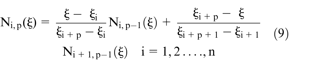
The isogeometric analysis (IGA) method has been developed by Hughes et al. (2005) in order to bridge the substantial bottleneck between the CAD geometry and analysis for an exact representation of a domain. The application of IGA approach to the structure enhances complex domain problem-solving capacity with high accuracy and precision. The IGA has capabilities of accurate geometry modeling even with coarse mesh sizes, which is found very difficult to achieve using FEA using standard Lagrange basis functions. The solution of problems using IGA method allows the parametric space refinement with a higher order of approximation. By changing the NURBS order, the continuity or smooth stress distribution of the solution can be achieved, which is extremely difficult to achieve in FEM with a
Cohesive zone modeling (CZM) is widely used for simulations of crack initiation and propagation in laminated composite structures. The CZM approach has been implemented into finite element formulation for crack propagation modeling utilizing negligible thickness cohesive elements (Bouhala et al., 2013). A physical discontinuity in the domain can be numerically modeled using the concept of extended finite element method (XFEM) (Bouhala et al., 2015). Motamedi and Milani (2013) applied the combined concept of XFEM and CZM for nonlinear delamination growth modeling in the 3D domain of double cantilever beam (DCB) specimens. Numerical models have been presented for delamination growth simulations in two-dimensional and three-dimensional composite structures using isogeometric cohesive elements by exploiting knot insertion directly from CAD geometry (Hughes et al., 2005; Nguyen et al., 2014; Piegl and Tiller, 1995). Ghorashi et al. (2012) introduced a new numerical method for fracture modeling by the introduction of XFEM into IGA, known as Extended Isogeometric Analysis (XIGA). In this method, a physical discontinuity in the material domain can be modeled as independent from the geometric mesh and crack propagation simulation without the requirement of re-meshing (Ghorashi et al., 2012). The applications of XIGA methodology has been further extended for fatigue life estimation and crack propagation investigations in the orthotropic lamina (Kaushik and Ghosh, 2019b). Implementation of XIGA methodology for interlaminar crack propagation modeling has its challenges associated with crack tip enrichment functions because of the dependency of these functions on the type of analysis to be executed. These issues with the XIGA approach can be overcome by utilizing the major advantages of CZM in removal of crack tip stress singularities. Researchers have implemented the combined concept of linear elastic fracture mechanics (XFEM) and damage mechanics (CZM) for delamination modeling in laminated composites (Bouhala et al., 2013, 2015; Motamedi and Milani, 2013). Thus, a combined XIGA-CZM numerical framework can be utilized for crack evolution simulations with the consideration of material degradation and with the advantage of mesh independency (Kaushik and Ghosh, 2020, 2021).
The main focus of this work is to investigate the influence of actuation strain of macro fiber composite (MFC) actuators on suppression of crack propagation in unidirectional laminated composites (AS4/914). These investigations demonstrate the feasibility of Mode-I crack propagation control using smart materials. Very limited researches have been carried out about delamination or crack propagation control using piezoelectric materials and shape memory alloys. There is no literature available for crack or delamination propagation suppression using the MFC actuator in CFRP composites. The P1 type MFC actuators are selected for current research because of their high voltage operating range, higher free strain, high mechanical flexibility, and good blocking force. In this research work, the Mode-I fracture tests have been performed on DCB specimens having surface bonded MFC actuator patches under the application of electric voltage within a range of 0–1500 V. These fracture control tests are performed on non pre-cracked (NPC) and pre-cracked (PC) DCB specimens of aerospace grade unidirectional laminated composites (AS4/914). The influence of applied electric voltage on Mode-I fracture energy is investigated for different position of crosshead corresponding to different crack length. The modified pin force model has been utilized for the evaluation of actuation forces for numerical modeling of surface bonded MFC actuators. The XIGA-CZM based numerical formulation has been used for numerical fracture modeling under electromechanical loading conditions.
2. Experimental procedure
In the present work, Mode-I fracture tests have been carried out on a double cantilever beam (DCB) specimens having surface bonded Macro Fiber Composite (MFC) actuators. The experimental investigations have been performed for the crack suppression in aerospace grade unidirectional laminates using smart materials approach.
2.1. Materials and specifications
The aerospace grade laminated composite panels have been fabricated using Hexcel prepreg and reinforced with 914 trade epoxy resin system within AS4 fibers. The laminated composite panels have been fabricated by laying up 26 layers of prepreg material in symmetric sequence (
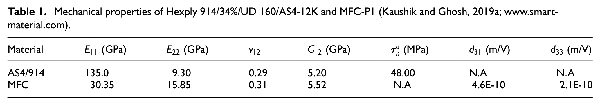
Mechanical properties of Hexply 914/34%/UD 160/AS4-12K and MFC-P1 (Kaushik and Ghosh, 2019a; www.smart-material.com).
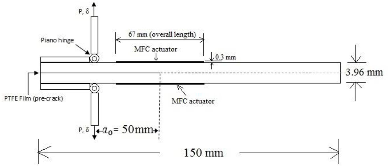
Schematic representation of DCB specimen with surface bonded MFC actuators.
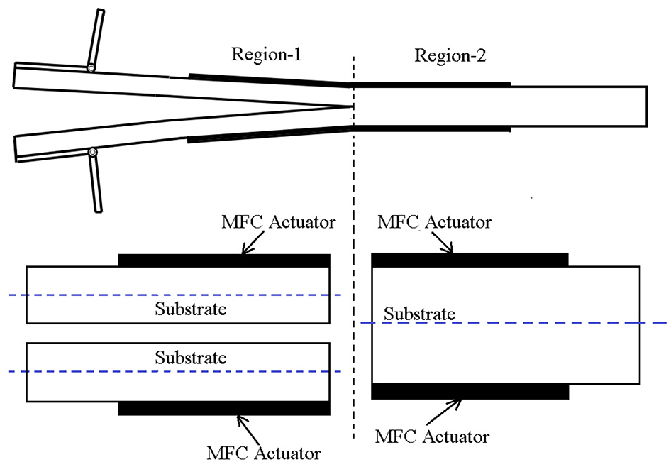
The specimens are fabricated with an interlaminar crack in the form of a Polytetrafluoroethylene film on one side of the specimen and these specimens are called as non pre-cracked specimens (NPC). If the NPC specimens are further tested under Mode-I static loading or by any other means under the crack or delamination propagates with a small amount, then the specimens are called pre-cracked (PC) specimens. Macro fiber composite (MFC) patches consist of rectangular piezoceramic rods sandwiched between layers of adhesive, electrodes, and polyimide film. These rectangular electrodes are attached to film in an interdigitated pattern which transfers the applied voltage MFC-structure directly to and from the ribbon-shaped rods. The specific type of MFC actuators used for crack propagation control in DCB specimens is P1-type, with an active dimension of 56 mm × 28 mm. These MFC actuators utilize the d33 effect for actuation and will elongate up to 1350 ppm (part per million) and can produce a blocking force up to 340 N if operated at the peak voltage of 1500 V. The material properties of these MFC actuators are given in Table 1. The schematic diagram of DCB specimen having surface bonded MFC actuator for Mode-I crack propagation control test is shown in Figure 1.
2.2. Experimental setup
The experimental setup for crack propagation control using Macro Fiber Composites (MFC) actuators bonded with DCB specimens is shown in Figure 2. The crack propagation control experiments have been carried out on Universal Testing Machine (UTM) equipped with some additional equipments such as; 5 kN Load cell with attached digital display, MFC actuators and High voltage power supply.
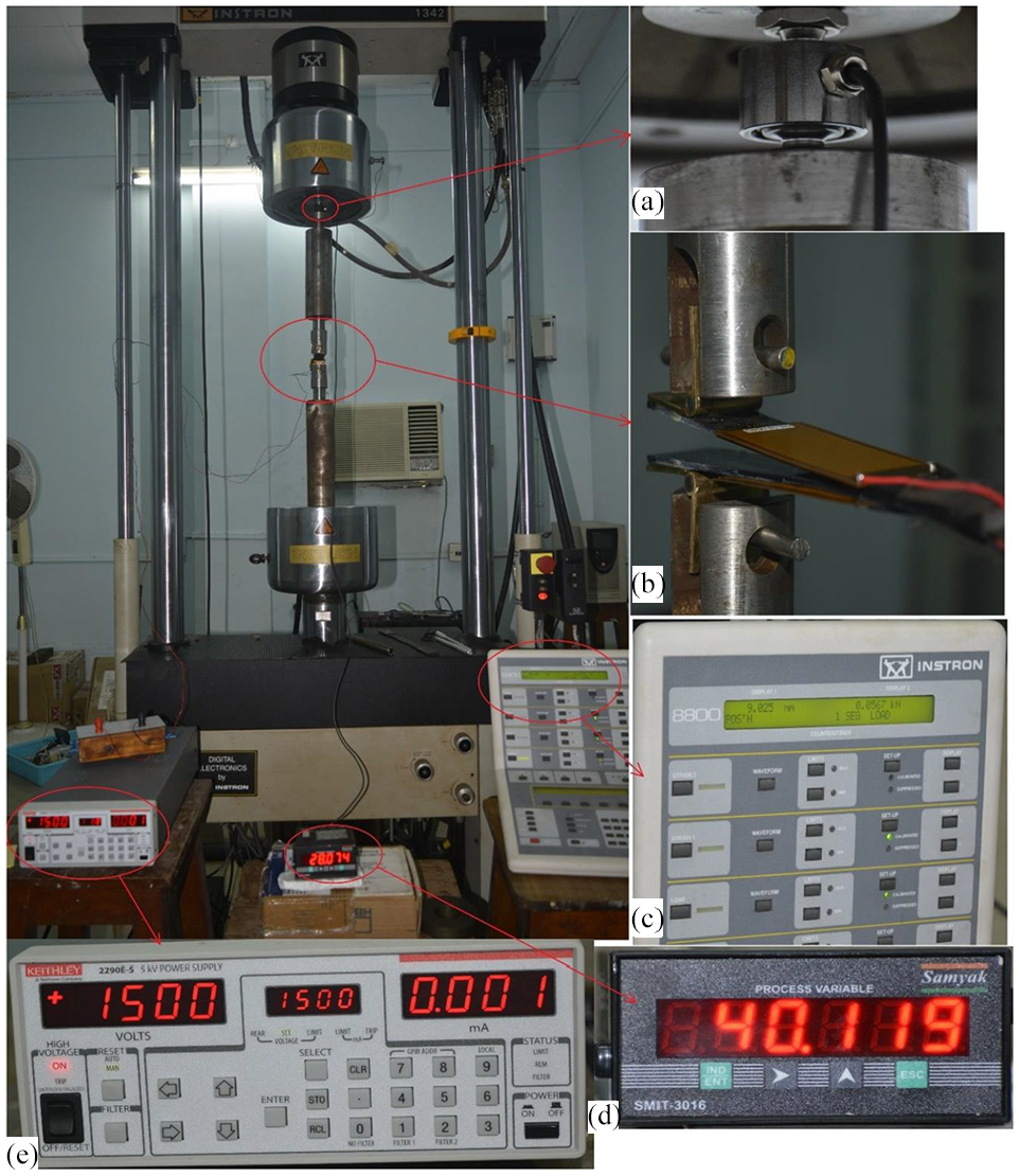
Experimental setup for Mode-I crack propagation control using MFC actuator (a) 5 kN load cell, (b) DCB specimen with surface boned MFC Actuator, (c) Operating Panel, (d) Load cell display and (e) High voltage power supply.
A 5 kN load cell (U9C) has been used for accurate measurement of small range load values, as shown in Figure 2(a). A special arrangement has been made to attach this additional load cell to the upper crosshead. The MFC (M5628P1MFC) actuators have been surface bonded to the DCB specimens of unidirectional laminated composites (Figures 2(b) and 3). The high dielectric breakdown strength (Loctite AA 324) adhesive has been utilized for surface bonding of MFC actuators to the composite specimen to avoid any possibilities of a short circuit at high applied voltage. The MFC actuators have been surface bonded on both sides of the specimens at the desired positions. The piezoelectric material has a very high electrical resistance in the range of Teraohm and they draw very less current in the range of nA. So, the selection of power supply is based on a required peak voltage with a minimal current limit for high accuracy and safety purpose. A 5 kV high voltage power supply (Model 2290-5) having a lower maximum current limit of 5 mA has been utilized for high voltage supply to the MFC actuators (Figure 2(e)). This power supply has been operated manually from the front panel of the instrument as shown in Figure 2(e).
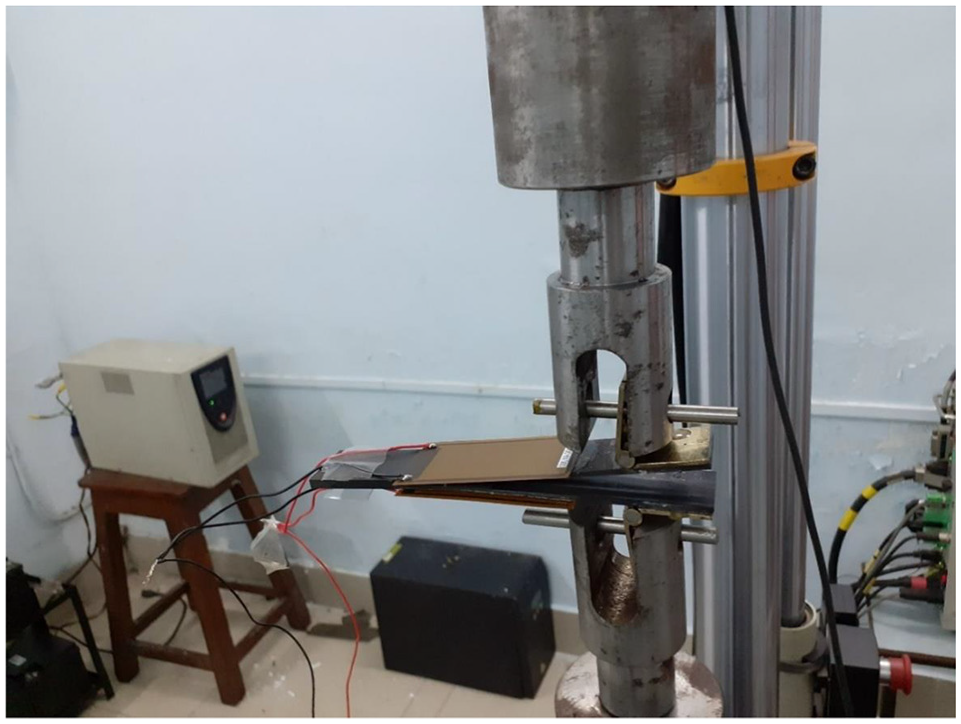
Mode-I fracture testing of DCB specimen with surface bonded MFC actuators.
2.3. Test procedure
The opening mode (Mode-I) fracture testing has been carried out on DCB specimens using a servo hydraulic UTM machine. It applies tensile load through mounted piano hinges as shown in the test fixture (Figure 3). The Mode-I test fixture has been designed similar to compact tension (CT) test fixtures in order to attach additional load cell along the loading axis. This additional 5 kN load cell has been used for recording accurate load values during Mode-I fracture tests. The crosshead displacement values have been recorded from an operating panel (Figure 2(c)). A video camera is used for recording simultaneous load and displacement values from the load Indicator digital display (Figure 2(d)) and the operating panel (Figure 2(c)), respectively. All the Mode-I fracture tests have been performed at a quasi-static loading rate of 0.5 mm/min by following ASTM D5528 standard (ASTM Standard, 2007). Three specimens have been tested for each test category in order to assure the consistency of experimentally obtained results. The MFC patches are bonded on both sides of the composite DCB specimen at the desired location from crack front as shown in schematic diagram (Figure 1).
The MFC patch bonding location on the specimen has been decided based on numerical simulations in order to achieve maximum crack suppression in the non pre-cracked specimen. These patches have been bonded to the specimen in such a manner that the actuation strain is parallel to the crack propagation direction. The numerical procedure for fracture simulations in DCB specimens under the influence of electromechanical loading is discussed in section 3. A high voltage power supply (Keithley, Model 2290-5) has been used to supply positive voltage to the MFC actuator patches within a range of 0–1500 V. The selection of a specific power supply is purely based on the type of actuator and application. During this crack propagation control test, the DCB specimens are loaded at a quasi-static rate and followed by holding them at the specified crosshead position for application of electric voltage. The load values are recorded at the held crosshead position for corresponding applied voltage of 0, 250, 500, 750, 1000, 1250, and 1500 V. Similarly, the load values have been recorded during releasing applied voltage from 1500 to 0 V at the same intervals. In these tests, the nature of a load-displacement response has been observed under the application of electric voltage to the bonded actuators. This loading process has been repeated with increasing crosshead position in small intervals such as; 0.5, 1, 1.5 … 6.5 mm.
The main aim of this increasing crosshead position and holding it at a specified position is to investigate the influence of supply voltage to the MFC actuators at different crack mouth opening displacements. The influence of MFC actuators active response on crack propagation has been investigated in unidirectional laminated composites. During these tests, the supply voltage, load value, and crosshead position need to be recorded simultaneously. The compliance based beam method (CBBM) is adopted for the evaluation of effective delamination length while fracture testing. This CBBM method for evaluation of the effective crack length, which considers the effect of arm rotation in DCB specimens at the delamination front with the incorporation of correction term. This effective crack length evaluation method is derived based on corrected beam theory (Wilk, 2018):
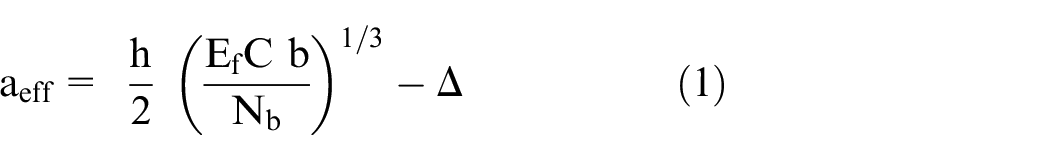
where b, h are the specimen width and thickness respectively,
3. Numerical formulation
The numerical simulations have been performed for crack propagation control in DCB specimens using smart materials actuation model with a combined framework of linear elastic fracture mechanics and damage mechanics.
In this numerical model, crack propagation occurs until the equilibrium has been achieved between internal and external forces. When the crack tip normal displacement exceeds the corresponding critical value, the crack advances automatically by enriching the element length in the front of crack tip. The physical crack face has been modeled using extended isogeometric analysis (XIGA) approach and crack tip propagation is simulated using cohesive zone modeling (CZM). The surface bonded MFC actuators exerts a mechanical force on the substrate under the application of electric voltage to the actuators. So, the actuation forces from the MFC actuators are calculated using modified pin force model as discussed in the section 3.4. The summation of actuation forces obtained from modified pin force model at the pin locations and mechanical loading at the piano hinges leads to complete numerical fracture modeling of DCB specimen under electromechanical loading conditions.
3.1. Boundary value problem
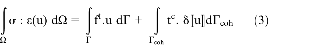
The total potential energy formulation for a domain with a cohesive crack propagation modeling can be expressed with the consideration of crack face traction forces. The force equilibrium equation for the body can be written as:

where
where

The standard finite element galerkin discretization method has been implemented in the governing equation (equation (3)). The governing equation in terms of FEM shape functions and nodal variables, along with the relative crack opening displacement can be expressed as:
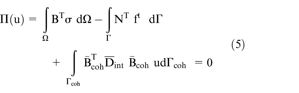
where B matrix contains derivatives of shape functions,
3.2. XIGA formulation
In XIGA, the NURBS functions have been utilized at the place of conventional finite element Lagrange’s basis function. The physical crack in the domain has been simulated using Heaviside enrichment functions and crack evolution path in the material has been tracked utilizing 2D level set functions. Displacement approximation can be expressed as (Ghorashi et al., 2012; Hughes et al., 2005; Motamedi and Milani, 2013; Nguyen et al., 2014):

where

Where
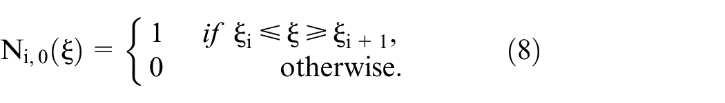
for the polynomial of an order p ≥ 1
The level set method has been adopted to track the stationary and propagation crack in the two-dimensional domain with respect to existing mesh in the material domain. The Heaviside enrichment functions can be expressed as (Ghorashi et al., 2012):


where
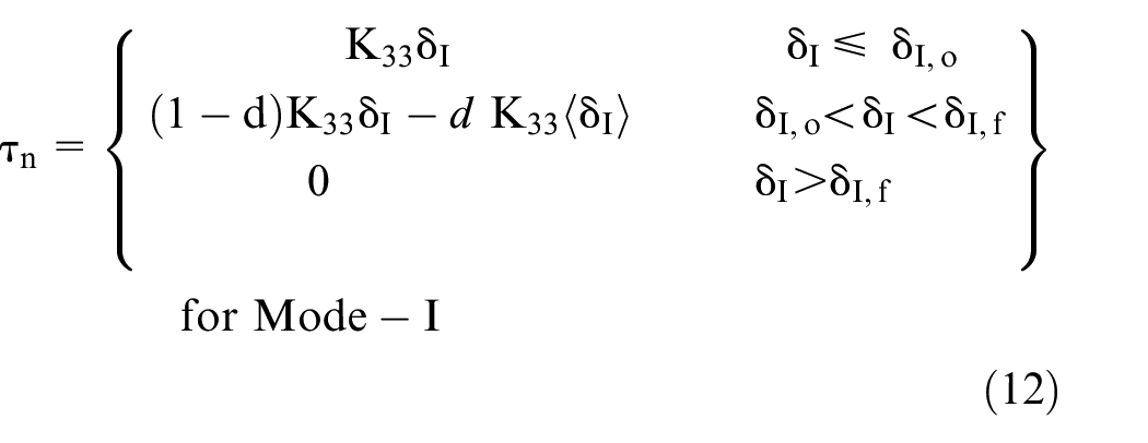
3.3. Cohesive zone modeling
The CZM method has been utilized to describe the damage initiation and propagation in the laminated composites. The opening mode (Mode-I) critical displacement
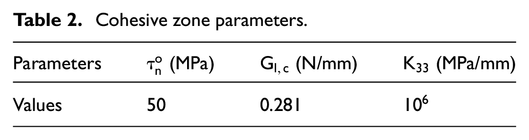
Cohesive zone parameters.
The constitutive relations for the two-dimensional damage model can be defined as (Turon et al., 2007):
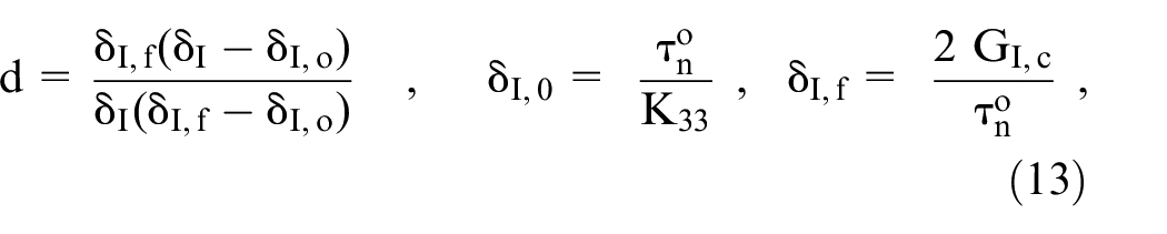
where d represents the scalar damage parameter,
3.4. MFC actuation model
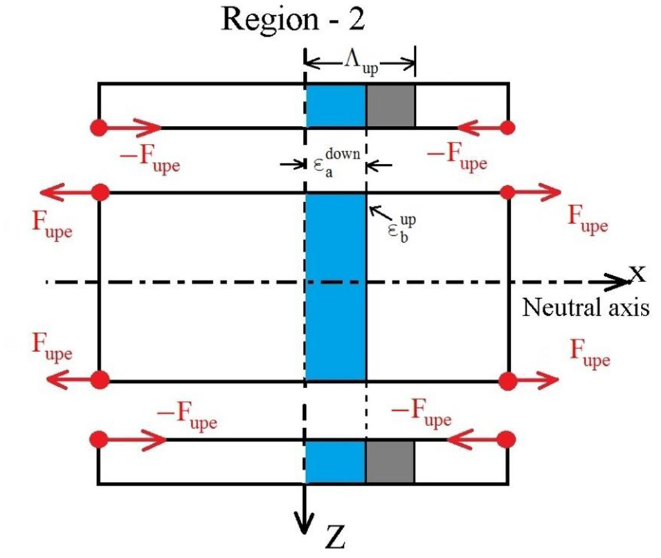
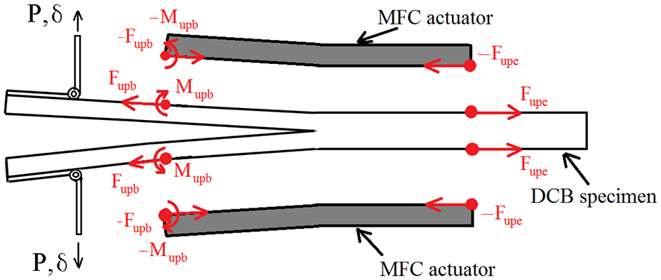
A modified pin force model (MPFM) has been adopted for the evaluation of actuation force exerted by the surface bonded MFC actuators on the unidirectional laminated composite substrate (Figure 4). This model is derived from consideration of active material patch and substrate as two structures with different strain-regular, linked together by pins at the edges of the actuator (Figures 5 and 6). A perfect bonding is assumed between the actuator and substrate for numerical simulations. The strain compatibility conditions need to be satisfied at the interface, which is the pin location. The mechanical pin connection between the actuator and the substrate is assumed and force transferred in the two parts is only the pin force
Schematic diagram of the DCB specimen for pin force modeling.
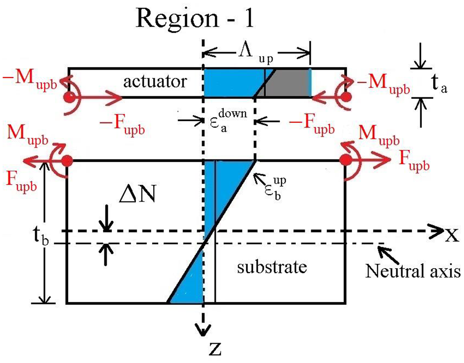
Modified pin force model for the unimorph structure in Region-1.
Pin force model for the pure extension of a composite structure in Region-2.
Pin force model for loaded DCB specimen with surface bonded MFC actuators.
Region-1 in the schematic diagram represents the cracked part of a loaded DCB specimen and an electric voltage applied to the MFC actuator will induce both bending and extension in the beam. A positive voltage will induce extension as well as positive bending of the bean. The graphic description of a modified pin force model for actuation modeling in Region-1 is shown in Figure 5. The strain of actuator at an interface (
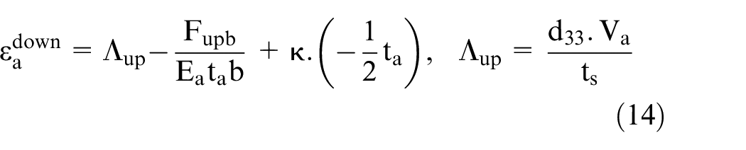
where
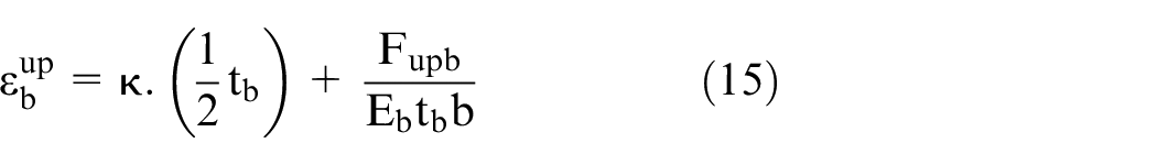
Satisfying displacement continuity condition at the bonded interface of the composite structure:

The resultant moment of the actuator has been transferred through the pin connection with the consideration of actuator bending stiffness, which can be expressed as (Chaudhry and Rogers, 1994; Li et al., 2016):

Similarly, the resultant moment of the substrate can be expressed as:

The curvature of this unimorph structure can be derived using equations (14)–(18), given as (Chaudhry and Rogers, 1994; Li et al., 2016):
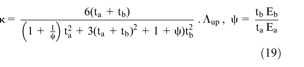
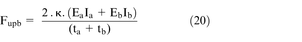
The actuation force at the pin connection in unimorph structure in Region-1 can be derived using equations (17)–(19) and can be written as (Chaudhry and Rogers, 1994; Li et al., 2016):
The Region-2 in a schematic diagram represents the case of pure extension in the beam for the same applied voltage to both lower and upper bonded MFC actuators (Figure 6). The strain of actuator at an interface (
The axial strain in the composite substrate can be expressed as (Chopra and Sirohi, 2013):
For displacement compatibility between substrate and bonded actuator,
The complete pin force model for DCB specimen under Mode-I loading conditions with surface bonded active material at an applied electric voltage is shown in Figure 7.
4. Results and discussion
The opening mode (Mode-I) fracture tests have been carried out on DCB specimens under a displacement control mode by holding crosshead at the specified position for an application of electric voltage to the actuators. The influence of applied electric voltage on Mode-I fracture energy is investigated for different crack opening displacements. The modified pin force model has been adopted for the evaluation of actuation forces in numerical modeling. The XIGA-CZM based numerical formulation has been utilized for numerical crack propagation simulations under electromechanical loading conditions. The Mode-I fracture tests have been carried out on non pre-cracked (NPC) and pre-cracked (PC) specimens with a fixed position of surface bonded MFC actuators on the unidirectional laminated composite substrate. The Mode-I fracture tests have been performed on three DCB specimens in order to assure the consistency of experimental observations. The average values of Mode-I energy release rates obtained from the fracture tests of three specimens are utilized for the validation of numerical results.
4.1. Non pre-cracked (NPC) specimen tests
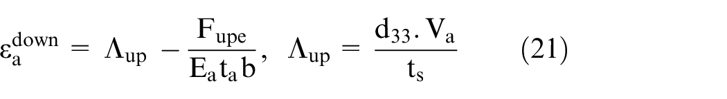
In this research work, the opening mode (Mode-I) fracture tests have been performed on non pre-cracked DCB specimens under the application of an electric voltage within a range of 0–1500 V. The center of MFC actuator is located at the delamination front as shown in Figure 4. The MFC actuators exert a crack closer force and moment on the substrate due to the application of electric voltage to the active material. The nature of active material expansion or contraction and amount of actuation force exertion critically depends on the supply voltage, type of bonded actuator and stiffness of the bonded substrate. The piezoelectric materials can expand or contract up to their free strain value and exert actuation force within the range of zero to their blocking force. The effect of an applied electric voltage to the bonded actuator on Mode-I energy release rates has been investigated with increasing crosshead displacement in the range of 0.5–3 mm (Figures 8–10).
Fracture energy w.r.t applied voltage at crosshead positions of 0.5 and 1 mm.
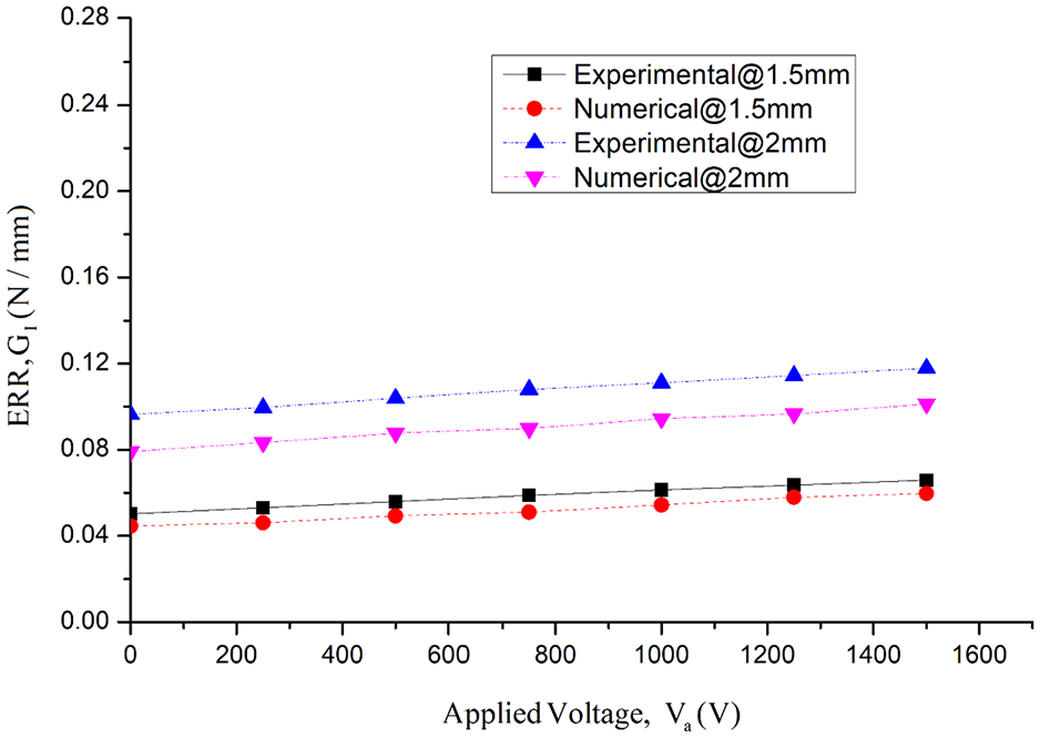
Fracture energy w.r.t applied voltage at crosshead positions of 1.5 and 2 mm.
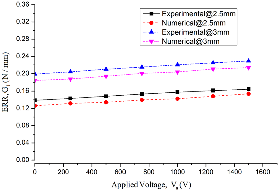
Fracture energy w.r.t applied voltage at crosshead positions of 2.5 and 3 mm.
It is observed that the Mode-I energy release rate (ERR) increases with an increase in applied electric voltage to the MFC actuators, which represents the influence of actuation forces on the specimens. The percentage change in ERR w.r.t corresponding electric voltage is shown in Table 3 for several crosshead positions in the NPC specimen. A significant increase in ERR has been observed at peak operating voltage for lower crosshead position and it decreases with an increase in crosshead position (Table 3).
Mode-I fracture energy data for different crosshead positions at applied voltage.
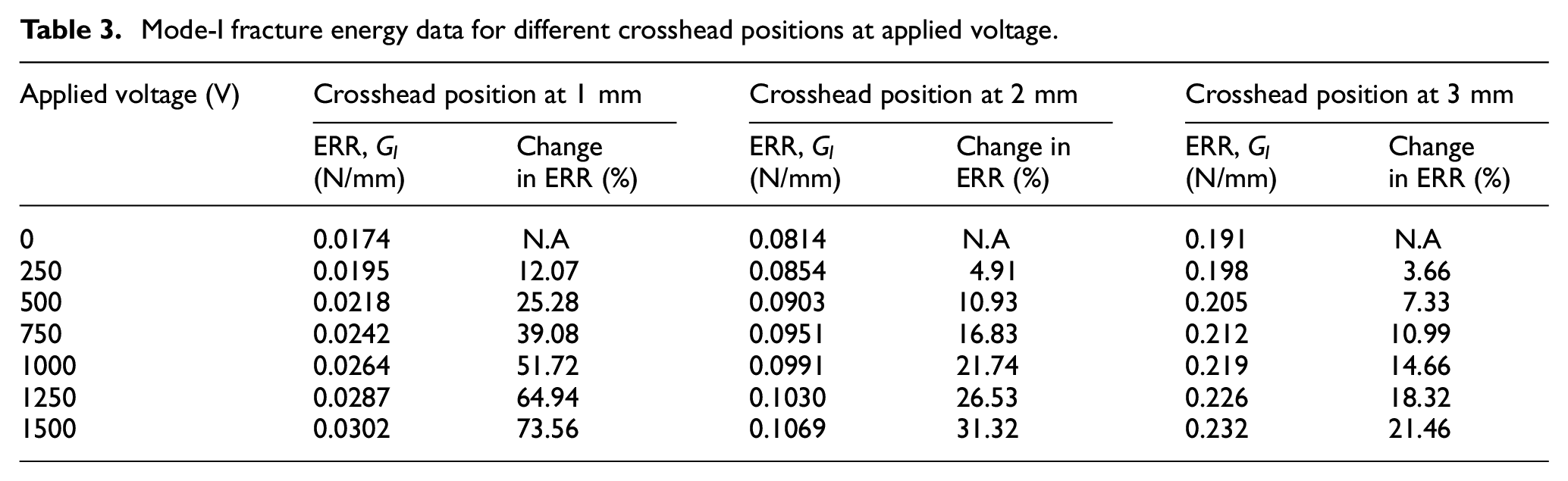
From these observations, it can be concluded that MFC actuators have significant control on opening mode fracture energy under the application of peak operating voltage. The numerical simulations utilizing a modified pin force model in combination with XIGA-CZM based fracture model shows a good agreement with experimentally obtained results (Figures 8–10).
4.2. Pre-cracked (PC) specimen tests
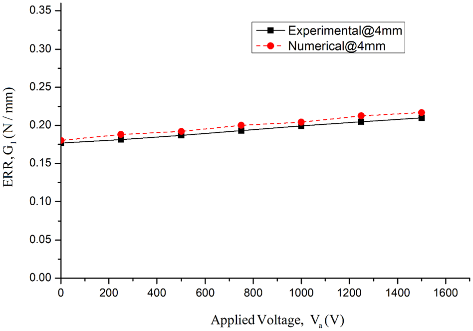
In this section, the influence of surface bonded MFC actuator patches on Mode-I fracture in pre-cracked DCB specimens is investigated under the application of electric voltage. The pre-cracking of unidirectional laminated composite DCB specimens is performed by testing specimens under Mode-I static loading till crack or delamination propagates by a small amount. During pre-cracking of specimens, the crack propagates by a small amount and the center of bonded MFC patch is no more coincide with the delamination front. Mode-I fracture testings have been carried on pre-cracked (PC) specimens in displacement control mode followed by holding test at specified crosshead positions for application of electric voltage. This test is performed for several crosshead positions, as shown in Figures 11 to 16.
Fracture energy w.r.t an applied voltage at a crosshead position of 4 mm.
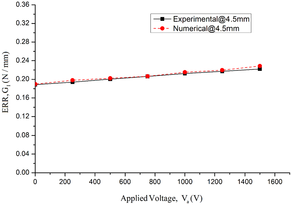
Fracture energy w.r.t an applied voltage at a crosshead position of 4.5 mm.
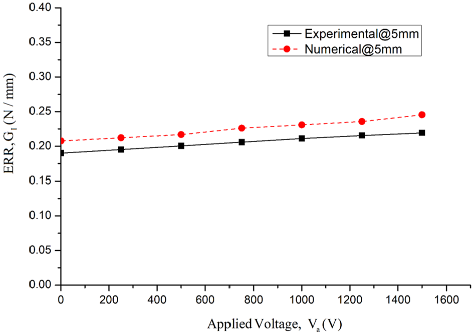
Fracture energy w.r.t an applied voltage at a crosshead position of 5 mm.

Fracture energy w.r.t an applied voltage at a crosshead position of 5.5 mm.
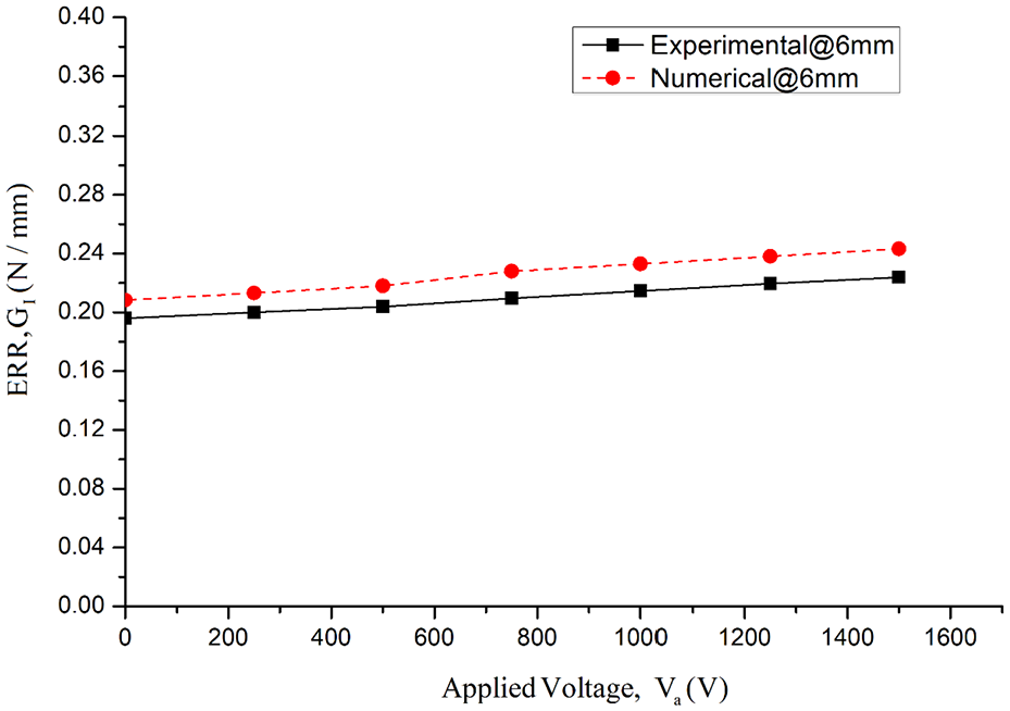
Fracture energy w.r.t an applied voltage at a crosshead position of 6 mm.
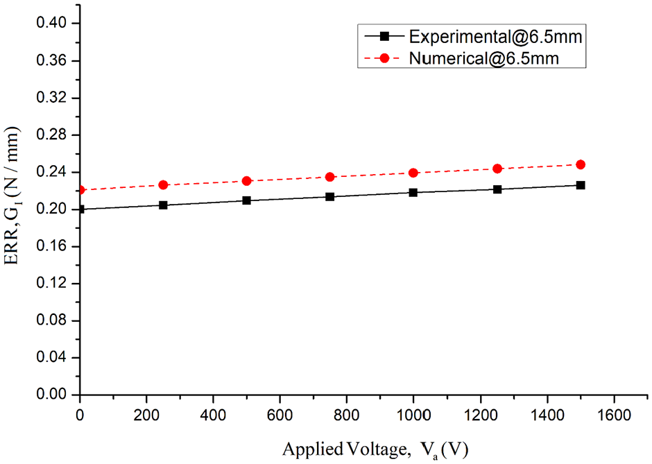
Fracture energy w.r.t an applied voltage at a crosshead position of 6.5 mm.
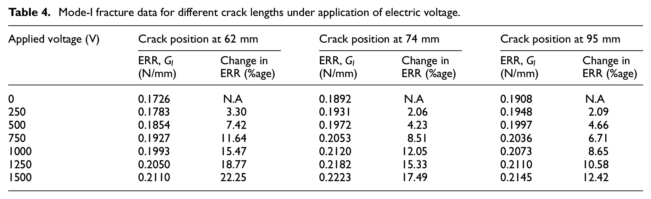
In PC specimen tests, the crack or delamination propagates with an increase in loading displacement (Figure 17). The Mode-I critical fracture energy has been plotted w.r.t corresponding applied voltage to investigate the influence of actuation forces on fracture energy during crack propagation (Figures 11–16). It is observed that the Mode-I critical fracture energy increases with an increase in supply voltage for the corresponding crosshead position and achieve its maximum actuation at a peak operating voltage of 1500 V. The percentage change in Mode-I critical energy release rate w.r.t corresponding electric voltage is represented in tabular form for several crack lengths (Table 4). It is observed that the least smart material actuation response (around 12%) has been found at the crack length of around 95 mm, where the crack front exceeds the length of MFC actuator patch. Once the crack front exceeds the length of a bonded MFC actuator patch, the whole model is considered as an unimorph structure for numerical simulations. The numerical simulations utilizing a modified pin force model in combination with XIGA-CZM based fracture model shows a good agreement with experimentally obtained results (Figures 11–16).
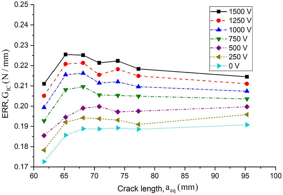
Fracture energy w.r.t equivalent crack length for the different applied voltage.
Mode-I fracture data for different crack lengths under application of electric voltage.
From these observations, it can be concluded that the macro fiber composite actuator showed a significant control over opening mode fracture energy when operating at peak supply voltage. A small variation in experimental observations has been observed in comparison to the numerical results. During numerical simulations, a perfect bonding has been assumed between MFC actuators and laminated composite substrate. But during experiments, the perfect bonding and proper alignment of MFC actuators with substrates are the challenging tasks and they may lead to some error in experimental observations. These manual errors may lead to some variation in experimental observations and numerical simulations. The influence of macro fiber composite (MFC) actuator response on Mode-I critical fracture energy during crack propagation under the influence of an applied electric field is represented in Figure 17. It may be concluded that the control of active material over Mode-I fracture energy reduces with crack propagation.
5. Summary and conclusions
In this work, the opening mode stationary and propagating delamination tests have been performed on DCB specimens having surface bonded MFC actuator patches under the application of electric voltage to the actuators within a range of 0–1500 V. These tests have been carried out on non pre-cracked (NPC) and pre-cracked (PC) specimens of aerospace grade unidirectional laminated composites (AS4/914). The influence of applied electric voltage on Mode-I fracture energy has been investigated for different positions of loading crosshead and crack lengths. The modified pin force model has been utilized for the evaluation of actuation forces in surface bonded MFC actuators for numerical modeling. The XIGA-CZM based numerical formulation has been used for numerical crack propagation simulations under electromechanical loading conditions.
The MFC actuators exert a crack closer force and moment on the substrate under an application of electric voltage to the active materials. The Mode-I fracture energy increases with an increase in applied electric voltage to the MFC actuators, which represents the influence of actuation forces on the specimens. A significant increase in Mode-I fracture energy has been observed for lower crosshead position and it decreases with an increase in crosshead position. The active material actuation response reduces with crack propagation and it had the least influence on ERR when the crack front exceeds the length of bonded MFC actuator patch. The MFC actuators have significant control on opening mode fracture energy under the application of peak operating voltage. The numerical simulations utilizing a modified pin force model in combination with XIGA-CZM based fracture model shows a good agreement with experimental observations. The present experimental and numerical methodology can be utilized for further prediction of fracture control in laminated composites with an application of smart materials.
Footnotes
Declaration of conflicting interests
The author(s) declared no potential conflicts of interest with respect to the research, authorship, and/or publication of this article.
Funding
The author(s) disclosed receipt of the following financial support for the research, authorship, and/or publication of this article: The authors would like to acknowledge Aeronautics Research and Development Board (AR&DB), DRDO for their financial support (Grant no—ARDB/01/1051918/M/I) and Advanced Composite Division, CSIR-National Aerospace Laboratory, Bangalore for their technical support.