
Abstract
The shape memory alloy (SMA) is increasingly utilized among many industrial and civil applications as it is small in size but mighty in output. However, most of the current SMA-based mechanisms face with the low controllability or bulk dimension. In this paper, a novel flexible SMA wire-based gripper is developed to address these challenges for improving the clamping stability and stroke for confined operation. To achieve this, the long SMA wire was spaced smartly within a miniature space to increase the output, further, to improve the stroke of the gripper (14 mm vs conventional 2 mm). Then, the theoretical model of the system was established by considering the thermal effect of SMA material and the static performance of the flexible beams. After that, the experimental setups were prototyped to crossly test the performances of the proposed SMA gripper. It can be seen from the experimental results that the model presented in this paper can be validated with high accuracy (error: 3.4%). It can also be found that the SMA gripper can realize the high tracking performances (i.e. 8.9% accuracy in displacement step response, 10.8% in displacement tracking response, and 12.1% accuracy in clamping force tracking response, respectively) for the industrial applications.
Keywords
1. Introduction
New technologies in material promote the development of the existing devices to make the life more convenient. As one kind of the end-effector, the gripper is widely used to achieve the clamping functions for the robots or manipulators, such as the auto-feeder in the automobile assembly line (Zitzewitz et al., 2008) and apple picking machine in agriculture (Xiong et al., 2018). Hence, the gripper with miniature size, lightweight, and better performance are highly required in high-tech applications (Ma et al., 2018, 2020a). However, due to the bulk size of the current actuators (e.g. motor), it is challenging to reduce the dimension of grippers for a further step. In this paper, an intelligent kind of actuator (i.e. SMA wire), which has the unique abilities (e.g. miniatured size, powerful output, and stable phase transformation), is adopted to achieve the clamping ability with large stroke, aiming to improve the development of the research for smart material and robotics (Jani et al., 2014; Sun et al., 2012).
Currently, SMA-based mechanisms have been extensively used among various areas, such as aerospace, automobile (Bil et al., 2013; Hartl and Lagoudas, 2007), medical (Morgan, 2004), and robotics (Ma et al., 2020b). However, for most of the time, the SMAs are usually fabricated as a part of the whole device to achieve the required SME when the external temperature varies. For example, a kind of jellyfish robot was manufactured by Villanueva et al. (2011) to realize the flapping motion of patagium using the built-in SMA strips. Then the overall movement of jellyfish can be achieved. Then, a robot bat, which SMA drove to realize the flapping and morphing motions of the wings, was designed and fabricated by Colorado et al. (2012). Besides that, some attempts were performed by using the SMA wire/spring as actuators to drive the motion of mechanisms (i.e. robot joint). The single degree of freedom (DoF) rotational joints actuated by SMA wire was developed by Kolansky et al. (2015) and Guo et al. (2015) to achieve the rotational motion, which has an operating frequency of 4 Hz with the assisted cooling method. Then, a 3-DoF robotic arm was researched by Ashrafiuon et al. (2006), in which SMA wires drove the rotational motions of the three joints. Further, the 15-DoF robot hands were designed and fabricated by Price et al. (2007) and Kim (Maeno and Hino, 2006) to study the motion characteristics and control methods using more SMA wires as actuators. In addition, a kind of locomotive robot, which was driven by the SMA springs, was made and tested by Kim et al. (2005) for medical inspection. However, the locomotive speed was limited by the heating and cooling rate of SMA springs.
Some researchers tried to use SMA to design the grippers with miniature dimensions. For example, Yan et al. (2007) designed a kind of gripper in which the two moveable parts were driven by the differential SMA springs. However, the clamping stability and position accuracy was limited by the poor controllability of SMA springs. Further, Menciassi et al. (2005) developed a miniature SMA wire-based clamping mechanism, which was used in the medical assistant for the inside diagnosis. But the stroke of the system is too small for performing the practical work. Compared with the previous research for the SMA-actuated devices, the novelties for combining the SMA wire and the flexible gripper to minimize the dimension and improve the stroke can be summarized as follows: One is that the SMA wire was utilized as the actuator to drive the clamping of the two flexible beams. Comparing with the conventional actuation methods (e.g. motor (Liu et al., 2020), and hydraulic actuator (Nie et al., 2020)), the SMA actuator has its nature advantages to reduce the dimension of the system, as well as to provide the flexible intervention with the environment; further, the stroke of the gripper has been largely improved (i.e. 14 mm vs conventional 2 mm (Liang et al., 2017)) by the new design of the actuation system (i.e. the long SMA wire was twined in a novel way to minimize the space) and novel structure of the flexible beams; then, based on the novel structure of the gripper, the new modeling method of SMA gripper, which considers the thermal effect model of SMA wire and mechanical behavior of flexible beams, was developed to study the performance of the SMA gripper comprehensively.
In this paper, a novel kind of SMA wire-based gripper was developed for unconventional applications (e.g. confined space collection with the snake robot as an example). To extensively study the SMA gripper for better application, the theoretical model was established, as well as the experiments under different conditions were implemented. After briefly the concept and structure design of the gripper was introduced, the parameters of the gripper (i.e. stiffness of the flexible beams, type of the SMA wire) were selected with the help of FEA simulations. Then the models of the SMA wire and the gripper were established, which considered the phrase transformation and heat dissipation of the SMA wire, as well as the elastic deformation and force reaction of the flexible beams. Next, the case study was performed to validate the theoretical model of the SMA gripper developed in this paper. After that, a set of tests (i.e. step response, tracking response, and mode switch response) were performed to research the performances comprehensively. At last, the discussion and conclusion are made.
2. Application background and gripper design
As an example, the snake robots are crossly developed to perform the deep/inside tasks that hard/impossible for the conventional robots (e.g. arm robot and parallel robot), enabling access into the highly confined spaces to perform the inspection/repair tasks. However, currently, most of the work performed by the snake robot is relating to delivering the various end effectors (e.g. cameras and machining tools) inside the equipment for conducting the general operations. To the author’s best knowledge, the research/development of the collection end effector falls behind with the snake robot.
Based on the abovementioned challenges, a novel kind of gripper, which has the attributes of lightweight, miniature dimension, and flexible clamping, was developed to combine with the existing snake robot, aiming to perform the collaborative task in the confined environments. The novel flexible SMA gripper, which is composed of a pair of beams and SMA wires, is proposed in this section to realize the interaction with objects. Further to extend the application, the clamping stroke and force are designed to be adjustable by using an intelligent prismatic joint for the environment with different features.
2.1. Gripper concept and structure design
The schematic diagram of the SMA gripper is shown as the top part of Figure 2, where the SMA wire is adopted as the actuator to drive the deformation of the flexible beams. When the current is applied on the SMA wire, the length will be changed by the phase transformation of its internal microstructure. Then, the pulling force will be generated to actuate the deformation of the flexible beams. However, using the SMA wire as the actuator involves the challenges for designing the actuation system, where the long SMA wire was needed to generate the required strain for the flexible beams. To solve this problem, an intelligent mechanism that constructed by the parallelly distributed small pullies is developed to reduce the dimension of the overall system.
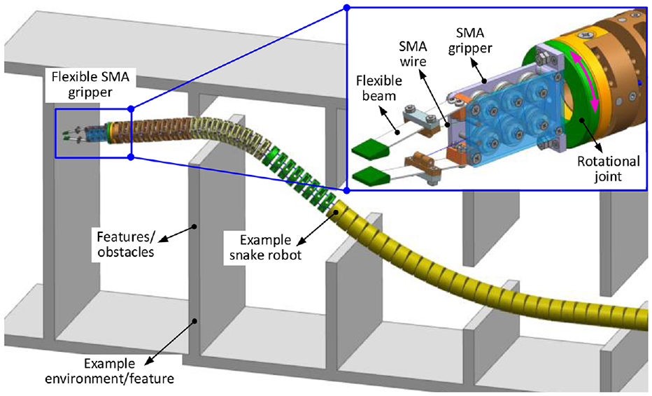
One example application of the developed SMA gripper for the existing in-situ robot. The SMA gripper is equipped at the tip of the snake robot for the deep/inside operation, enabling to perform the interaction with the environment/equipment.
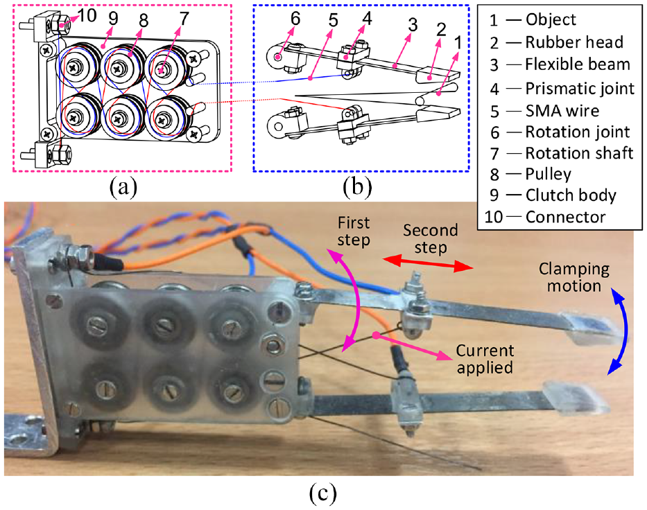
The schematic diagram design and prototype of the SMA gripper: (a) is the actuation system of the SMA wire distribution, (b) is the structure of the flexible gripper and (c) is prototype of the SMA gripper.
As the SMA wire can only realize the one-way strain effect when the temperature is changed, the energy-storing system is required to push the SMA wire back to the initial position after releasing the SMA wire.
The conventional method to obtain the two-way motion of the SMA wire is to use a kind of spring unit (e.g. torsional spring) to push the SMA wire back. However, this method will complicate the structure of the overall system. In this paper, the novel flexible beams were selected to provide the restoring force by its elastic deformation, which will simplify the structure of the gripper.
The prototype of the SMA gripper is shown as the bottom part of Figure 2, which is composed of two components (i.e. actuation system and flexible gripper, respectively). Two independent SMA wires are twinned on the parallelly distributed pulleys to minimize the actuation system and reduce the friction. The operating process for the gripper can be described as: firstly, adjusting the initial assembly angle of the two rotational joints (part 6) to change the clamping stroke; Secondly, changing the positions of two prismatic joints (part 4) to match the stroke of SMA wires with gripper; Then, applying the current on the SMA wire to induce the phase transformation (part 5) for producing the required strains; Next, the generated stress in SMA wires can drive the deformation of two flexible beams (part 3). At last, the gripper can clamp the object (part 1) that located between two rubber heads (part 2).
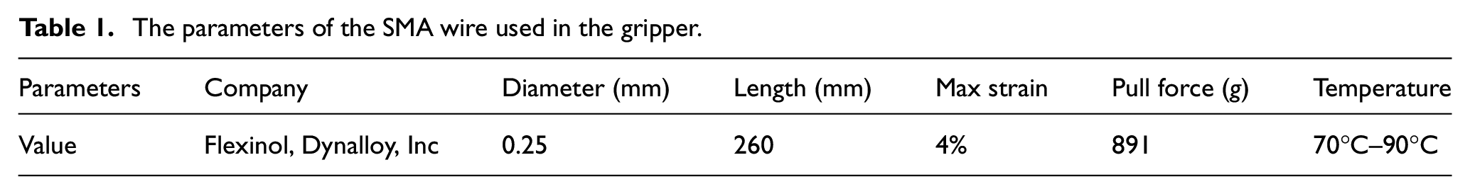
Based on the performance of the SMA wire, it can produce around 891g pulling force with the full phase transformation of the SMA material (i.e. from martensite structure to austenite structure). In order to achieve the better working performance, the parameters of the two beams should be carefully designed as well. The parameters of the SMA wires used in the gripper are shown in Table 1.
The parameters of the SMA wire used in the gripper.
2.2. Flexible gripper design
The flexible beams with high flexibility are adopted for clamping with the objects, as seen in Figure 3. As the gripper is constructed by two identical flexible beams, to simply the calculation, one beam is selected for the modeling (seen in Figure 3). The location position for the SMA wire is designed to be adjustable, enabling to adjust the stroke of the gripper for clamping the object with different dimensions. This is achieved by changing the position of the prismatic joint on the flexible beam,
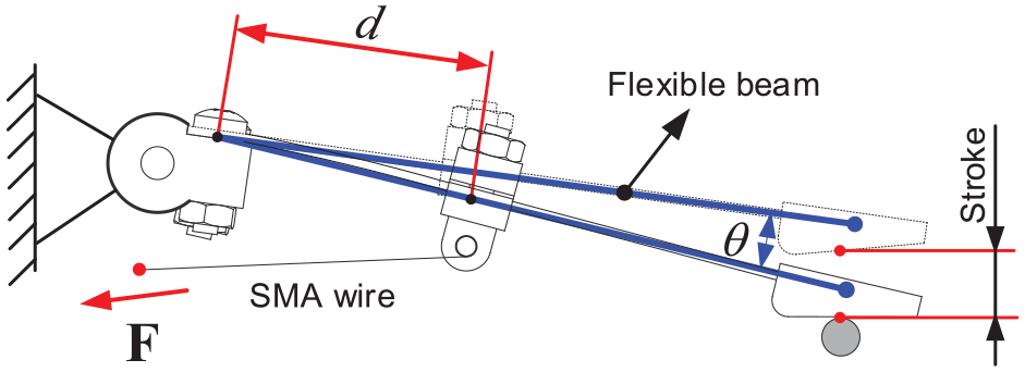
The working principle for the selected part of the SMA griper.
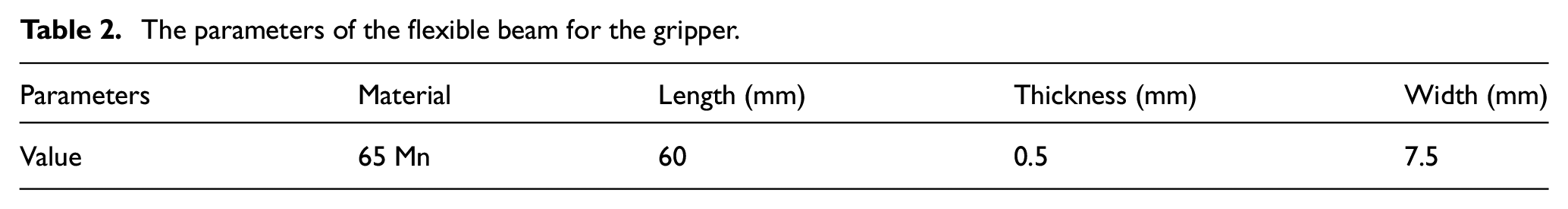
In order to select the appropriate parameters for the flexible beams, the simulation is implemented at first to check the required pulling force for the SMA wire, shown in Figure 4(a). The pulling force is imposed on the SMA wire to actuate the flexible beams to the desired deformation, and then the pulling force is recorded for the further study, seen in Figure 4(b). The parameters of the flexible beams are shown in Table 2.
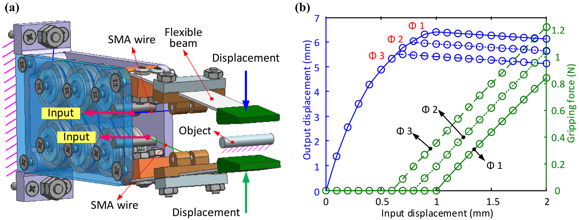
The structure design and the simulation results of the SMA gripper: (a) the structure design of the gripper and (b) the simulation results for the gripper (i.e. displacement and clamping force) under the input displacement of the SMA wires.
The parameters of the flexible beam for the gripper.
It can be seen from Figure 4(b) that the displacement output and gripping force can be obtained under continuous displacement inputs of the SMA wires. The performance responses (i.e. gripping force and output displacement) of the gripper with different size of the objects (i.e. 1, 2, and 3 mm diameters) located at the gap are different. For the output displacement, with the increase of the input displacements, the gripper tips are closing to contact the objects sequentially (i.e.
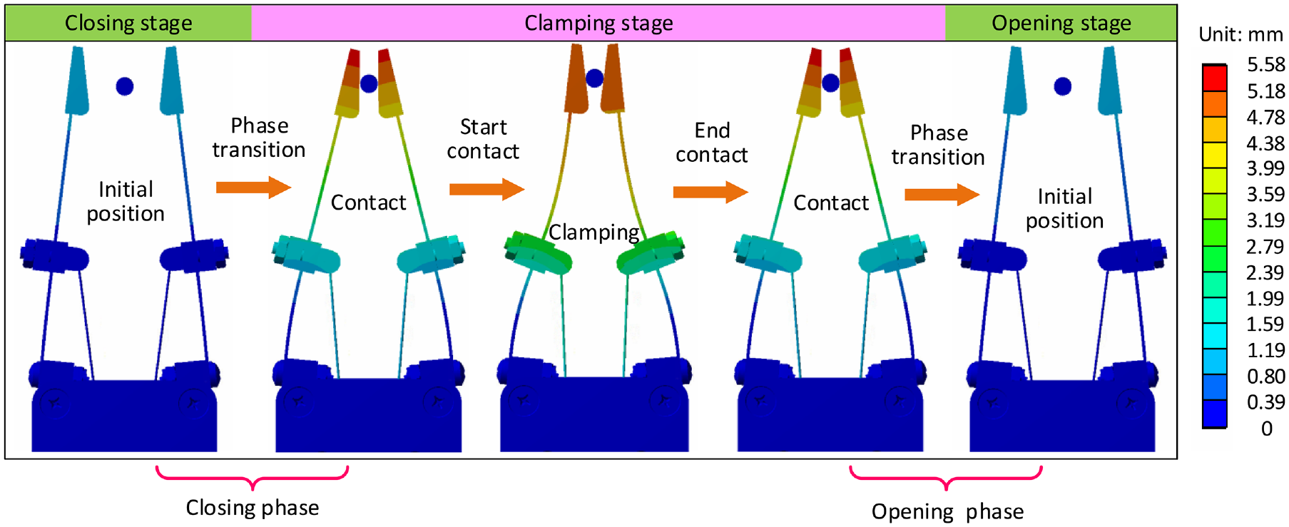
Deformation/shape of the flexible beams at different stages with the aid of simulation.
The deformation/shape of the flexible beam in different stages (i.e. closing stage, clamping stage, and opening stage) can be obtained with the aid of the ANSYS software, which helps to detailly study the shape variation of the flexible beams in a working cycle of the gripper.
Figure 5 illustrates the shape of the flexible beams under the continuous displacement inputs of the SMA wires for a working cycle. One working cycle can be divided into the three stages, and they are the closing stage, clamping stage, and opening stage, respectively. In the closing stage, the two flexible beams are closing toward the object, which is located at the center of the gap; In the clamping stage, the tip of the two flexible beams have been contacted with the object, leading to the gradually increase of the gripping force; in the opening stage, the two flexible beams are leaving the object and back to the initial position.
When the current is applied on the SMA wire, the temperature will be increasing gradually, leading to the deformation of the two flexible beams. When the current is “OFF,” the temperature of the SMA wire will be dropping gradually. The material structure of the SMA wire will be transformed from the austenite to martensite, where the flexible beams will be back to the initial position/shape. After analyzing the performance of the gripper under different input displacements, the parameters of the flexible beams can be selected to maximum the performance of the gripper. In next chapter, the model of the gripper will be developed to provide the guidance for the control system design.
3. Thermal effect model of the SMA wire and gripper
In this section, the novel continuous thermal effect model of the SMA wire and the gripper is presented. By using the developed model, the output of the gripper (i.e. displacement) can be calculated under the given input (i.e. voltage on the SMA wire), which can provide the important information (e.g. required voltage and heating time for SMA wire) for designing the control algorithm of the system.
3.1. Modeling the SMA wire
The gripper is actuated by a constitutive SMA wire with one end fixed on the flexible beam and another fixed on the body. As the motion of the flexible beams (on the top part of the gripper) is actuated by the length variation of the SMA wire, establishing the model of the SMA wire is becoming essential for controlling of the gripper. The constitutive thermal effect equation is adopted to establish the phase transformation degree of the SMA wire with the temperature variation. The shrink motion of the SMA wire can be obtained to actuate the movement of the gripper. According to the previous research (Arghavani et al., 2010; Brinson, 1993; Liang et al., 1997), the constitutive equation of a single SMA wire is defined by the relation of rate change in stress, rate change in strain, temperature change, and martensite fraction. Then the equation (1) can be established as follows:

Where
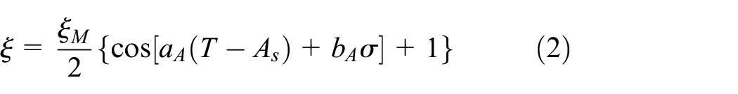
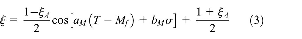
The SMA wire is sensitive to the temperature since the phase transformation will be happened when the temperature is higher or lower than the phase change temperature. In the initial state, the SMA wire is in cool temperature (under
The martensite fraction was used in defining the degree of phase transformation of the SMA wire in the previous literature. During the heating stage (from martensite to austenite), the martensite fraction can be expressed as:
While in the cooling stage, the martensite fraction (from to austenite to martensite) is defined as,
Where,
Based on the law of energy conservation, the power produced by the current should be equal to the temperature increase in the wire and energy dissipation in the system.
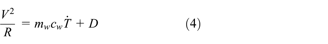
Where

Where

Where
After calculated the input power from the current, the temperature variation of the SMA wire can be calculated using equation (4). Then, the phase transformation can be computed by using equations (2) and (3) to get the stress and strain in the SMA wire. After that, the motion of the gripper and the clamping force can be calculated.
3.2. Modeling the flexible beam
The flexible beams of the gripper will be bent under the pulling forces of the SMA wire to generate the clamping function. When the temperature of the SMA wire is changed, the driving force will be changed accordingly. In this part, the kinematics equation of the flexible beams with the driving force of SMA wire will be studied for the control development of the next section.
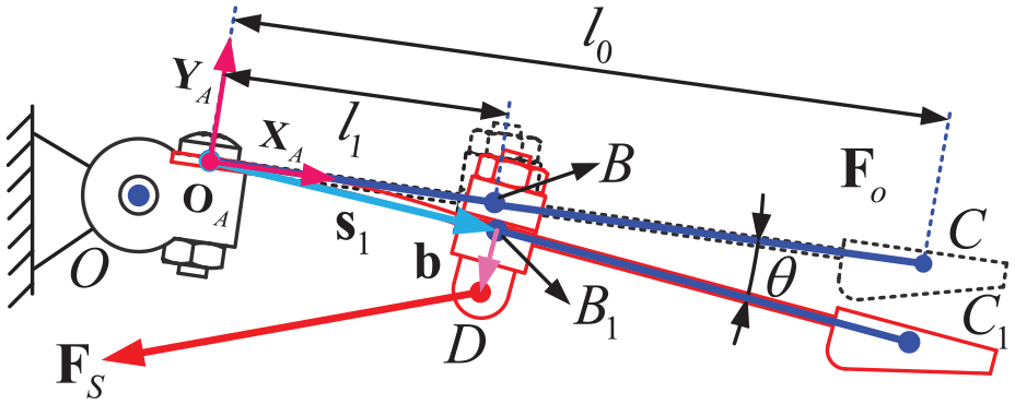
The flexible beam is forced by the SMA wire at point
Deformation of the flexible beam under external force.
The leaf coordinate system {A} is firstly defined to scale the deformation of the flexible beam. The origin of the coordinate system
Using the flexible beam theory, the flexibility matrix (Su et al., 2012) of a homogeneous beam can be expressed as following when the coordinate system is chosen as the beam center:
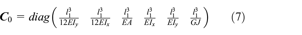
Where:
The transformation of the flexibility matrix under different coordinates can be expressed as:
Where,
Where
The external force caused by the SMA wire can be expressed as:
Where

Then, the equation to calculate the beam deformation can be established as follows:

Where
3.3. Modeling the SMA gripper
As the clamping motion of the gripper is divided into two stages (i.e. closing stage and clamping stage), the force model will be different. In the closing stage, as the gripper has not been contacted with the object, the force model is relatively simple. While in the clamping stage, the gripper has been contacted with the object. The contacting force between the head of the flexible beam and object will influence the force model of the gripper, where the force model will be complicated (Figure 7).

The static force analysis of the gripper.
The gripper coordinate system {C} is defined to establish the static equation of the gripper: The origin of the coordinate system
In the closing stage, the two flexible beams are moving to clamp the object by the driving forces from the SMA wires. As the gripper has not contacted with the object (upper part in Figure 7)), the elastic force of the flexible beam produced by the deformation will be balanced by the driving forces of the SMA wires, and the corresponding static equation can be expressed as:

Where

Where,
In the clamping stage, the gripper has contacted with the object. The contacting force from the object will influence the static model of the gripper. In this stage, the gripper is not moving any more, but the contacting force is increasing rapidly with the increase of the temperature of the SMA wires. The static equation of the gripper can be expressed as follows:

Where,
After defining all the initial conditions, the phase transformation model of SMA wire for driving the motion of gripper can be established using the equations (1)–(6) under the specific input (i.e. voltage); then, the static equation of the flexible beams can be developed under the two different working stages (i.e. closing stage and clamping stage) using the equations (7)–(15).
4. Experimental setup and validation
Based on the theoretical model of the SMA gripper proposed in the last section, the experiment setup, which includes the SMA gripper, control system, and measure system, was built to check the correctness of the model. As the current, temperature, and force are the essential factors to evaluate the performance of the gripper, they are measured by using the corresponding sensors (i.e. current sensor, temperature sensor, and force sensor, respectively).
4.1. Control algorithm design of the gripper
In the control system design of the SMA gripper, the voltage applied on the SMA wire were adjusted by the microprocessor (Ma and Song, 2003; Song et al., 2003). The overall process for controlling the SMA gripper is shown as follows: firstly, the upper monitor sends commends to the microprocessor (slave computer) through the communication port; then the control algorithm will be running in the microprocessor to generate the required voltage to the driver; after that, the phase transformation in the SMA wire will be happened with the applied voltage; at last, the output of the system (i.e. displacement, pressure, and temperature) collected from the sensors will be feedbacked to the microprocessor for the closed-loop control algorithm design (Epps and Chopra, 2001; Heinonen et al., 2008; Song et al., 2003).
The flow chart of the control system for the SMA gripper is shown in Figure 8. In order to analyze the performances of the gripper thoroughly, three working stages are considered. Different sensors are used in different stages (i.e. the position sensor is used in the closing stage, the force sensor is used in the clamping stage, and the temperature sensor is used in all the stages), and then the corresponding control algorithms are programmed.

Flow chart of the control algorithm design for the SMA gripper.
The control system is divided into three parts in this paper: the first one is called the controller part, which is to transfer the input command into the PWM signals to drive the motion of the flexible beams. Firstly, the models of the SMA wire and flexible beam are established using the equations presented in section 3.1, and then the expected voltage is calculated for producing the PWMs to the drivers for heating the SMA wires. The second one is called the actuation part, in which the voltage is imposed on the SMA wires to force the phase transformations. The lengths of the SMA wires will be changed due to the phase transformation of the internal material, further causing the deformations of two flexible beams to clamp the object. The last part is the control algorithm design for these working stages (i.e. closing stage, clamping stage, and opening stage) for improving the performances of the SMA gripper. In addition, as the SMA wire is sensitive to the temperature, the temperature sensor is adopted in the process to monitor the temperature variation. If the temperature is higher than the set value, the system will be shut down to protect the system.
4.2. Experimental setup
The SMA gripper is fixed on the experimental table to perform the planned tests, seen in Figure 9. As the gripper is constructed by the two identical flexible beams, one is selected to implement the following tests. To do this, a supporting plate is placed at the gap of the gripper, with the displacement sensor is vertically placed on the rubber head of the gripper to capture the displacement variation. In addition, the SMA wire (i.e. diameter: 0.25 mm) is used to drive the motion of the flexible beam, with one end fixed on the flexible beam while another end fixed on the actuation system.
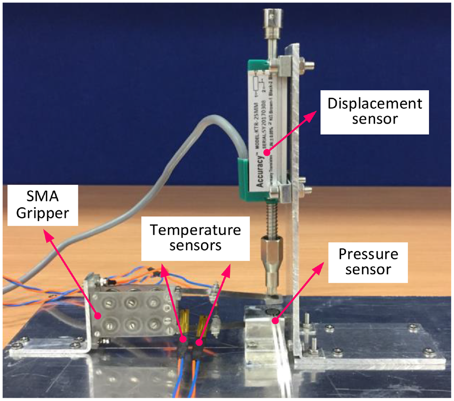
The experimental setup of the SMA gripper.
The algorithm runs in a microprocessor (type: STM32F103C6) to produce the command signals for the driver (type: MC33926) to change the voltage on the SMA wire. In addition, the driver can feedback the 0.24% load current as analog signal, which can be collected by the microprocessor and sent to the upper computer. The displacement sensor type: KTC-20 mm, with the resolution 0.012 mm) measures the motion of the flexible beam (located vertically on the gripper). The film pressure sensor (RFP-602) is glued on the plate that placed between the upper and lower platform to capture the clamping force. The temperature of the SMA wires is measured by the thin film thermal resistor temperature sensor (type: NTC10KB3950) and glued on the SAM wire using the thermal grease silver for the better heat conduction (Figure 9).
After finishing all the preparations (i.e. experimental setup, control algorithm design for the host computer, and slave computer) for the experimental setup, the performances of the SMA gripper can be studied, as well as the theoretical calculations presented in this paper can be validated.
4.3. Validation and performance tests
In this section, the experiments on the SMA gripper have been implemented to study the performances in the following aspects: first, the voltage responses of the SMA gripper under different voltages will be tested and compared with the theoretical calculations to validate the equations presented in this paper; then, the displacement step responses are performed to get the response time and positioning accuracy of SMA gripper; after that, the trajectory tracking experiments (i.e. sine motion trajectory) under different frequencies will be implemented to get the tracking ability of SMA gripper; at last, the force tracking investigations (i.e. sine clamping force trajectory) will be performed to test the clamping capability of SMA gripper in controlling the clamping pressure.
4.3.1. Voltage response
The voltage responses under different inputs are implemented to analyze the displacement responses of the SMA gripper, which are then used to validate the equations developed in this paper (Section 3). The voltages ranging from 1 to 2.5 V with 0.5 V intervals are applied on the SMA wire separately to implement the tests.
The voltage responses of the SMA gripper are shown in Figure 10, where Figure 10(a) is the displacement response of the gripper under different voltages. The selected measuring point is the geometrical center of the rubber head of the upper flexible beam (seen in Figure 2), which is the most concerned mechanical performance (e.g. clamping ability) of the developed gripper. Figure 10(b) to (d) are the corresponding current, temperature and clamping force responses of SMA gripper with the input of different voltages.
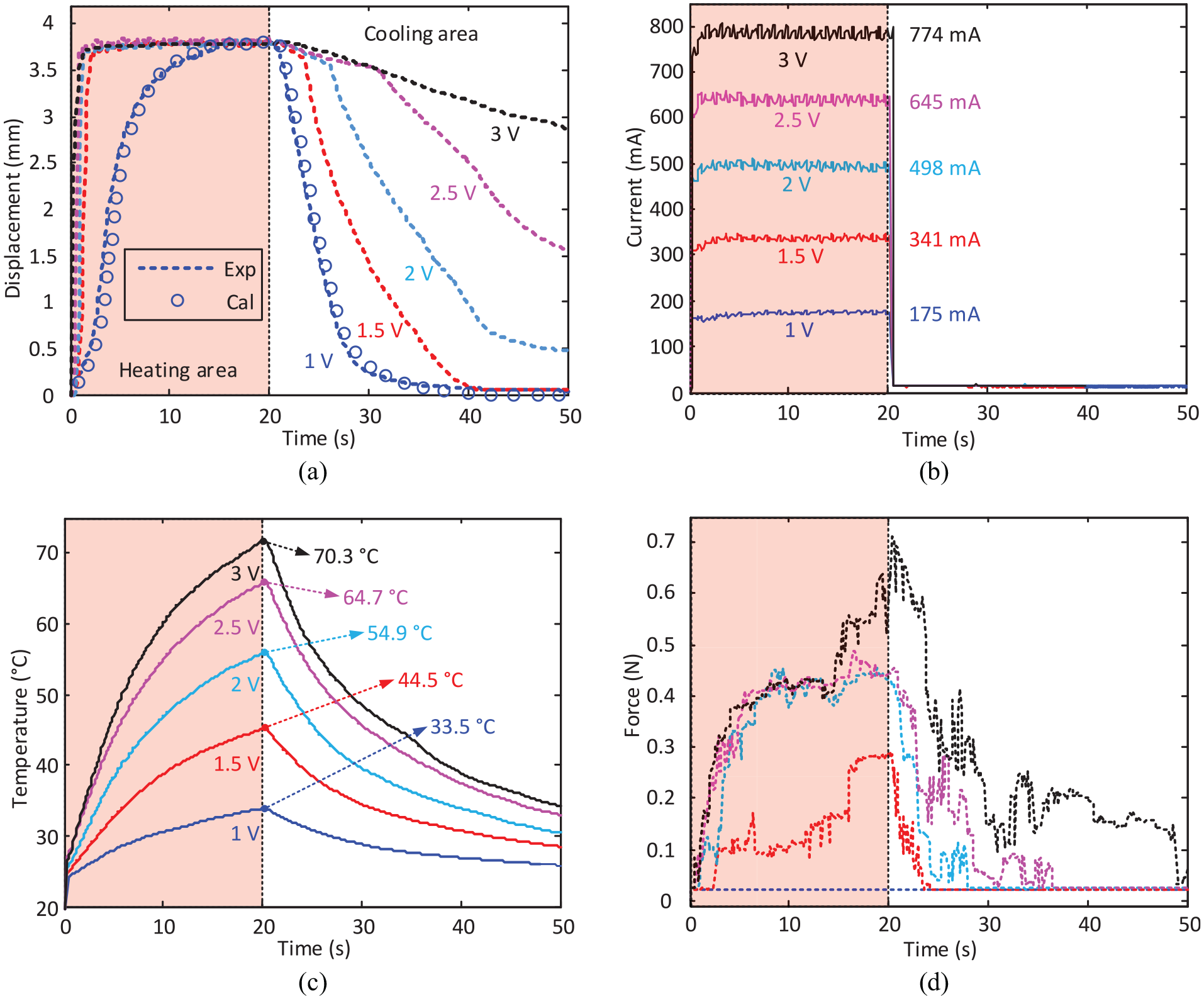
The response of the SMA gripper under different voltages: (a) the displacement variations of SMA gripper under different voltages and the comparison between experimental results and theoretical calculations, (b and c) are the current and temperature in SMA wire, and (d) is the clamping force variation during the test.
It can be seen from Figure 10(a) that the displacement outputs of the SMA gripper have a significant relationship with the input voltages. Specifically, the response time for the displacement variation (i.e. increasing and decreasing) in the heating and cooling stages are significantly affected by the voltages. The higher voltages will improve response time of the gripper (17, 1.1, 0.9, 0.8, and 0.75 s with 1, 1.5, 2, 2.5, and 3 V voltages, respectively). However, it will take longer time for the gripper back to the initial position (21, 22, 40, and more than 60 s with 1, 1.5, 2, and 2.5 V voltages, respectively). However, with the 3 V input, it takes more than 2 min for the gripper to back to the initial position. Under different voltage inputs, the stroke of the SMA gripper remains unchanged (3.7 mm). In addition, the equations developed in this paper are validated with the experimental results under 1 V voltage input (error: 3.4%), which proves the correctness of the developed model.
Figure 10(b) shows the current variation of the SMA gripper under different voltage inputs. The currents in the SMA gripper are proportional with the input voltages (175, 341, 498, 645, and 774 mA with 1, 1.5, 2, 2.5, and 3 V voltages, respectively), which indicates that the resistant of SMA wire almost keeps constant. In addition, the temperature of the SMA wire increases with the longer “on” time of the current, which can be seen from Figure 10(c). However, the currents in the SMA gripper seem unchanged, which means that the SMA wire is not sensitive to temperature.
Figure 10(c) presents the temperature variation of SMA wire under different voltage inputs. Generally, the temperatures gradually attend to the maximums before the voltage is turned off, and the maximum temperatures are about 33.5°C, 44.5°C, 54.9°C, 64.7°C, and 70.3°C, respectively. After the voltages switched off, the SMA wire takes a longer time to room temperature under higher voltage.
Figure 10(d) displays the clamping force variation of the SMA gripper under different voltages. The clamping force of the SMA gripper is much related to the voltages. The higher clamping force and shorter contacting time will be achieved with higher voltages. The maximum clamping forces of the SMA gripper are about 0, 0.27, 0.43, 0.5, and 0.71 N with 1, 1.5, 2, 2.5, and 3 V voltages, respectively. The maximum clamping forces under different voltages are happened at the time of the voltages switched off, meaning that stress in the SMA wire is related to the heating time. After the voltages are switched off, the clamping forces are gradually back to the initial conditions.
4.3.2. Displacement step response
With the developed closed-loop control algorithm, the step response under different voltages are implemented to test the response time and positioning accuracy of the SMA gripper. Specifically, with different displacements imposed on the control algorithm, the gripper is trying to track the given displacements with the closed-loop control algorithm. The step responses of the SMA gripper and the corresponding current are shown in Figure 11.
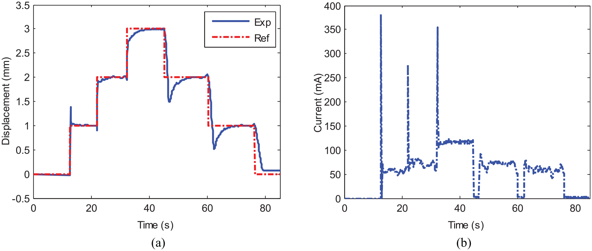
The step responses of the SMA gripper under displacement inputs: (a) the displacement responses of SMA gripper and (b) the corresponding current in the SMA wire.
Figure 11(a) presents the step responses of the SMA gripper under different inputs. The required displacements are scattered from 0 to 1, 2, and 3 mm successively, decreasing from 3 to 2, 1, and 0 mm. The corresponding positioning accuracies are 2.9%, 3.1%, 5.6%, 11.9%, 10.4%, and 19.9%, respectively, and the overall positioning accuracy is 8.9%. The overshoots at 1 mm in the increasing stage, 2 and 1 mm at decreasing stages are higher than the rest of the steps, and they are 38%, 45%, and 98%, respectively. Due to the restriction of heat dissipation, it is hard for the SMA gripper back to the initial stage (i.e. 0 mm displacement) quickly.
Figure 11(b) shows the corresponding current required in the SMA wire during the displacement step responses. In the increasing stage, as the higher energy/strain will be consumed when the displacement increases, the instantaneous currents reach to 375, 375, and 375 mA at the displacements of 1, 2, and 3 mm, respectively, and then keep at around 60, 74, and 123 mA respectively. In the decreasing stage, the currents drop to 0 mA at each step to reduce the temperature/strain of the SMA wire, and then the currents keep at around 76, 63, and 0 mA at the displacements of 2, 1, and 0 mm respectively.
4.3.3. Displacement trajectory tracking
The displacement tracking experiments of the SMA gripper under different frequencies are implemented in this section. To perform this, the sinusoidal trajectory is selected for the experiments. The corresponding control algorithm is designed for the SMA gripper to track the given trajectory. In addition, the currents in SMA wire are measured simultaneously for the further study.
The tracking responses of the SMA gripper under the different sinusoidal frequencies are shown in Figure 12. Figure 12(a) is the tracking responses of the gripper under different frequencies, while Figure 12(b) is the corresponding current and temperature variation during the experimental processes.
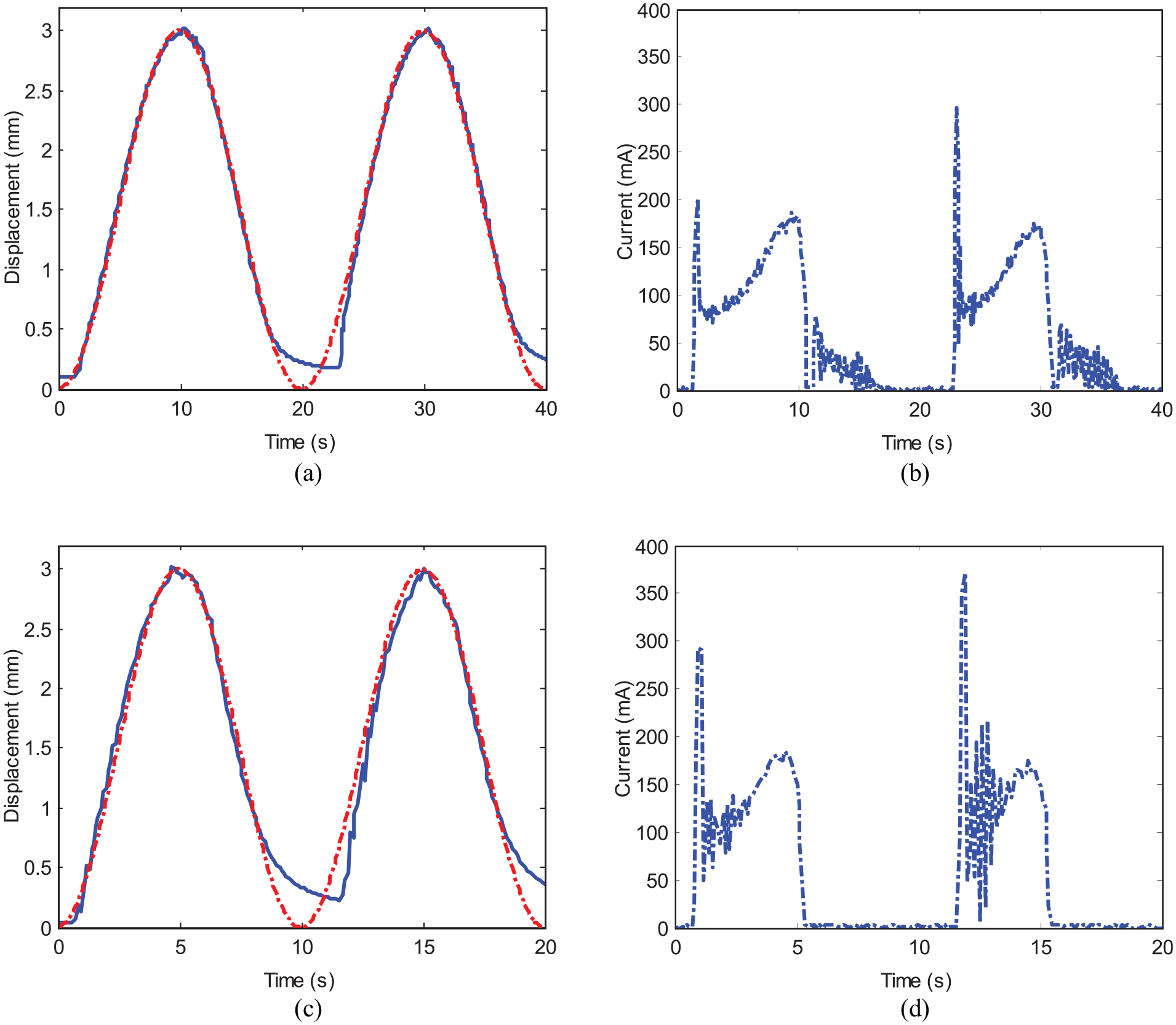
The tracking response of the SMA gripper under sinusoidal paths with the selected frequencies: (a and b) are the comparisons between the experimental results and the desired trajectories with the frequencies 1/40 and 1/20 Hz respectively and (c and d) are the corresponding currents during the trajectory tracking.
Figure 12(a) and (c) display the displacement tracking of the SMA gripper for the given trajectories (i.e. the frequencies are 1/40 and 1/20 Hz, respectively). Overall, the SMA gripper can track the provided paths with high accuracies (8.7% and 12.8%, respectively). Due to the heat dissipation restriction, the tracking error increases rapidly when the displacement drops under 0.5 mm, even the current reach to 0 mA.
Figure 12(b) and (d) show the corresponding current consumed when the SMA gripper is trying to track the required trajectories (i.e. 1/40 and 1/20 Hz, respectively). As the displacement variation in sinusoidal trajectory is steady compared with step response (Figure 11(b)), the degree of current fluctuation is moderate. Except for the large current peaks (1 s, 200 mA, and 22 s, 300 mA, in (b), 1 s, 300 mA, and 11.5 s, 370 mA, in (d)) at the beginning of each wave. With the increase of required displacement (from 0 to 3 mm), the currents are gradually increased to around 284 and 192 mA in trajectories1/40 and 1/20 Hz respectively, and then slowly drop to 0 mA in both of them.
4.3.4. Clamping force tracking
The clamping force tracking of the SMA gripper under the given force trajectory is performed in this part, which is utilized to test the ability of the SMA gripper for controlling the clamping force of the object. As the gripper is constructed by a pair of two symmetrically flexible beams and SMA wires, half part (one flexible beam with its SMA wire) is selected for the test. To do this, the force sensor is placed on the supporting plate to reflect the contacting force between the gripper and the supporting plate. Then the control algorithm running in the slave computer is used to track the clamping force.
As an example, the sinusoidal curve is selected for the clamping force tracking of the SMA gripper. With the aid of the closed-loop control algorithm, the voltage imposed on the gripper can be dynamically adjusted to change the strain/stress of the SMA wire (i.e. higher voltage vs higher strain/stress, vice versa), where the clamping force for the object can be adjusted, seen in Figure 13.
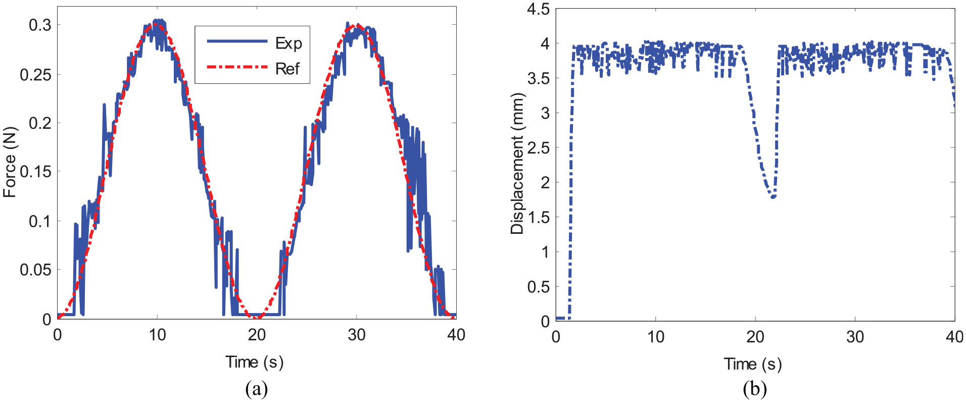
The clamping force tracking performance for the developed SMA gripper: (a) is the comparison of the real clamping force with the expected force path and (b) is the displacement variation of the flexible beam.
Figure 13(a) illustrates the performance of the SMA gripper for tracking the given curve (i.e. sinusoidal curve with 1/40 Hz period and 0.3 N amplitude as an example). Overall, the SMA gripper can follow the given force trajectory with decent accuracy (error: 12.1%). The higher deviation/vibration (error: 55.6%) of clamping force happens when the clamping force is lower than 0.1 N. One reason is that the clamping stability of the SMA gripper is lacking in the lower clamping force range. The other reason is that the SMA wire is sensitive to the voltage/current, which produces considerable stress for making the clamping force of the SMA gripper.
Figure 13(b) shows the corresponding displacement variation of the SMA gripper during the clamping force tracking. In the beginning, the displacement is increasing rapidly to a steady stage (3.8 mm), which means that the gripper has contacted with the object, and then the clamping force is controlled. When the clamping force is lower than 0.08 N (around 20 s), the displacement drops to about 1.8 mm, and the clamping force reaches to 0 N correspondingly.
In this section, the performances of the SMA gripper are tested with the aid of the developed control algorithm in the following aspects: voltage response, displacement step response, trajectory tracking, and clamping force tracking, respectively. From the experimental results, on the one hand, the theoretical model developed in this paper to forecast the displacement output under the given voltage is validated; on the other hand, from the performance test of the SMA gripper, it was found that it can realize the accurate positioning (8.9%), displacement tracking (10.8%), and clamping force tracking (12.1%) abilities, respectively.
5. Conclusion
In this paper, a novel kind of SMA wire-based gripper (characters: miniature dimension and large gripping stroke) is proposed, which is constituted by the actuation system (i.e. parallelly distributed SMA wires) and gripping system (i.e. flexible beams) to execute the flexible clamping with the objects. By regulating the current passing through the SMA wires, the stress/strain on the SMA wires can be controlled with the developed real-time control hardwire/algorithm. Based on the developed concept and structure of the SMA gripper, the theoretical models of SMA wire and flexible beams were developed, as well as the overall model of SMA gripper was built. The novelties and achievements of the proposed SMA wire-based gripper can be summarized as follows:
Firstly, an advanced SMA wire-based gripper, in which the SMA wire was utilized to provide the actuation force, and the flexible beam was adopted to interact with the object, has been developed to allow the flexible clamping with the environments. The actuation pack, which adopts a novel way to layout the SMA wires, has been demonstrated a useful way to reduce the weight and dimension of the system. Further, the adjustable attaching point of the SMA wire and the flexible beam can actively change the stroke of the gripper to adapt the varying environments. This method can be an effective way to increase the stroke and decrease the dimension and weight of the system.
Further, a novel thermal effect-based model on the developed SMA gripper was proposed, enabling to study the performance variation of the SMA gripper under different external voltages. With the prototyped test rig and control system, the developed model was validated with an error of 3.4%, which provides an effective way to guide the design of the SMA grippers (e.g. length required of the SMA wire, width, and thickness of the flexible beams). As the steel micro pulleys were used to guide the SMA wire, the heat dissertation to the micro pulleys will be much different with the heat dissertation to the air, which will influence the shape memory effect of the SMA wire. It will be one of the next works.
In addition, the experiments (i.e. displacement step response, displacement tracking response, and clamping force tracking response, respectively) were implemented with the aid of a close-loop control algorithm to comprehensively study the performance of the SMA gripper. The results indicate that the proposed SMA gripper in this paper can realize the high positioning speed (i.e. 0.2 s in Figure 11(a)) and accurate tracking accuracy (i.e. 8.9% in displacement step response, 10.8% in displacement tracking response, and 12.1% in clamping force tracking response, respectively). It can be found from the experimental results that SMA gripper developed in this paper can be a good end-effector to be combined with the existing robots (snake robot as an example in this paper) for the confined space operation.
Footnotes
Declaration of conflicting interests
The author(s) declared no potential conflicts of interest with respect to the research, authorship, and/or publication of this article.
Funding
The author(s) disclosed receipt of the following financial support for the research, authorship, and/or publication of this article: The research leading to these results has received funding from China Scholarship Council and Beijing Institute of Technology.