
Abstract
The main functions of automotive suspensions are to improve passenger comfort as well as vehicle dynamic performance. Simultaneously satisfying these functions is not possible because they require opposing suspension adjustments. This fundamental design trade-off can be solved with an active suspension system providing real-time modifications of the suspension behavior and vehicle attitude corrections. However, current active suspension actuator technologies have yet to reach a wide-spread commercial adoption due to excessive costs and performance limitations. This paper presents a design study assessing the potential of magnetorheological clutch actuators for automotive active suspension applications. An experimentally validated dynamic model is used to derive meaningful design requirements. An actuator design is proposed and built using a motor to feed counter-rotating MR clutches to provide upward and downward forces. Experimental characterization shows that all intended design requirements are met, and that the actuator can output a peak force of ±5300 N, a peak linear speed of ±1.9 m/s and a blocked-output force bandwidth of 92 Hz. When compared to other relevant technologies, the MR approach simultaneously shows both better force density and speeds (bandwidth) while adding minimal costs and weight. Results from this experimental assessment suggest that MR slippage actuation is promising for automotive active suspensions.
Keywords
1. Introduction
The main functions of automotive suspensions are to improve the level of comfort of the passengers as well as vehicle dynamic performance for safety and a better overall driving experience. However, simultaneously fulfilling these functions is not possible because they require opposing suspension characteristics. A softer suspension behavior is required to dampen road vibration and improve passenger comfort, whereas a stiffer behavior is necessary to improve tire contact with the road as well as the dynamic behavior of the vehicle while braking and cornering (Dixon, 2007; Rajamani, 2006). With traditional “passive” suspension systems, this is a big challenge for designers who must make compromises to find a balance according to their market segments. These compromises, coupled with irregular and unpredictable road profiles, inevitably induce undesirable motions and vibrations to the passengers. These undesirable motions can have negative health impacts over time according to ISO-2631, as well as being a main contributor to motion sickness (Diels and Bos, 2016).
An effective way to solve this problem is with semi-active or active suspensions that can cancel road vibrations and correct vehicle attitude during maneuvers. Although mechanically simpler, semi-active suspensions are fundamentally limited because they cannot provide vehicle attitude corrections and have limited capabilities for ride quality control with high frequency harshness due to the limited switching rate of the control system (Rajamani, 2006). Hence, there is an increasing interest among automotive manufacturers for a fully active suspension technology.
For the last 30 years, automotive manufacturers and research labs have attempted to develop a fast, strong and reliable active suspension system for on-road cars to increase safety, comfort and vehicle performance, and all that, at low costs. To date, four actuator technologies were developed: hydraulic, direct-drive electromagnetic, electromagnetic hydrostatic and geared electric motor.
1.1. Current automotive active suspension technologies
Hydraulic actuation was pioneered by the Williams F1 team in 1982 for improved aerodynamic performance (Howard, 2001). The proposed system is presented in Figure 1 and consists of a hydraulic pump coupled to accumulators connected to eight servo-valves (two per wheel). Each pair of antagonist valves can control the upwards and downwards force of a cylinder connected directly to the wheel. Other manufacturers have followed the same principle such as General Motors in 1988 (Petrany, 2020), and Mercedes with the ABC (Active Body Control) (Mercedes-Benz Media Newsroom Canada, 2006). Although very powerful, hydraulic actuators for automotive active suspension applications lack in reliability, are slow, and are expensive (Gysen et al., 2009).
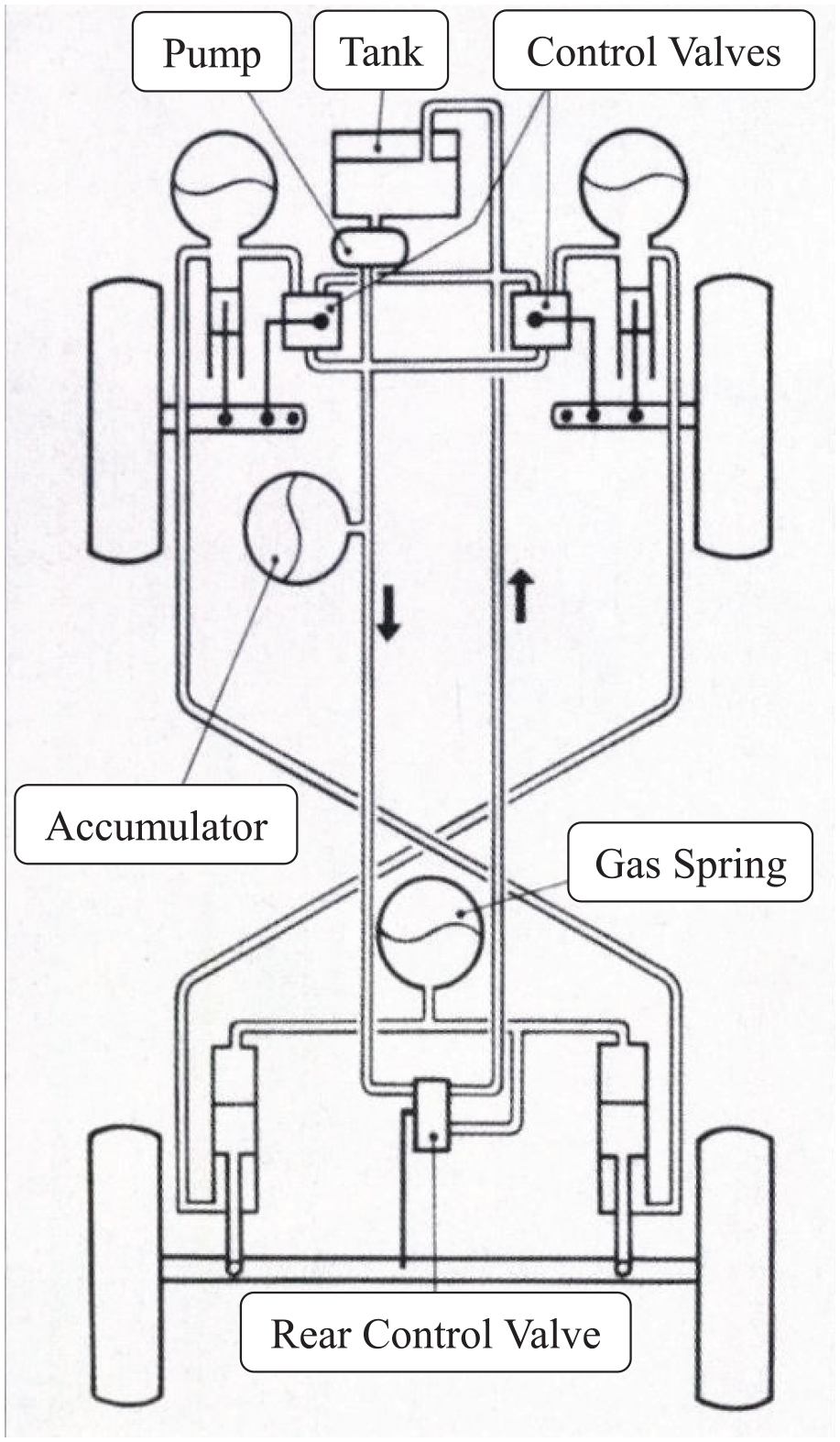
Hydraulic active suspension system of Williams’s F1 (Howard, 2001).
Direct-drive electromagnetic actuation technology was pioneered by BOSE in 2008 (Jones, 2005). The system is presented in Figure 2 and consists in four linear electromagnetic motors and a control unit. By sending a current to the linear motors, the electromagnet stator interacts with magnets mounted on a linear output generating controllable forces to each wheel. Although they have very high speed and bandwidth, direct-drive electromagnetic actuators for automotive active suspension applications are expensive, which is the main reason such technology is not available commercially (van der Sande, 2011).
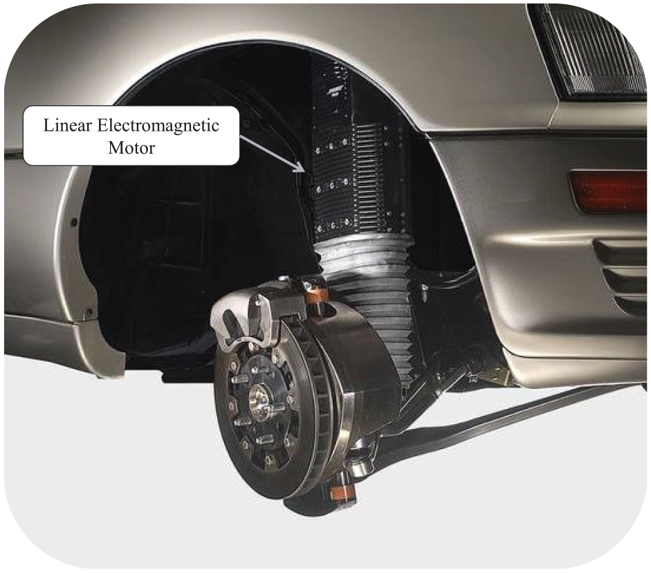
Direct-drive electromagnetic active suspension system of BOSE (Suspension Spot, 2018).
Electromagnetic hydrostatic actuation technology is being developed since 2007 by ClearMotion (Howard, 2017). The system is presented in Figure 3 and consists of four small servo-pumps which adjust the oil pressure directly in the stock dampers to control the force applied to the wheel (ClearMotion, 2018). Although compact, electromagnetic hydrostatic actuators for automotive active suspension applications have a low bandwidth that needs to be compensated for by control algorithms such as machine learning to try and predict the road profile rather than directly reacting to the disturbances. The strategy is to map every bump on every road, save the information in a cloud database, and then send real-time commands to the vehicles to react accordingly. This makes the technology more of a “Proactive” suspension system relying on software and a live connection to a huge and up-to-date cloud database in order to work properly (Sawers, 2019).
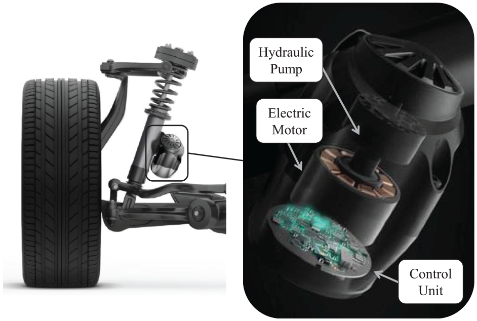
Electromagnetic hydrostatic active suspension system of ClearMotion (Citroën Vie, 2018).
Geared electric motor actuation technology was commercialized by Audi on its A8 model in 2018 (Adcock, 2017). It is the only active suspension system available on a production car. The system is presented in Figure 4 and consists in a highly-geared electric motor with a lever arm connected directly to the wheel. By changing the rotation direction of the motor, the system can either apply positive or negative forces on the wheel. The system is protected against back driving forces from the road by using a serial-elastic configuration where a spring is mounted between the geared motor and the wheel. Although very reliable and powerful, the combination of high gearing, motor reversal and serial-elastic configuration results in a low bandwidth (Adcock, 2017).
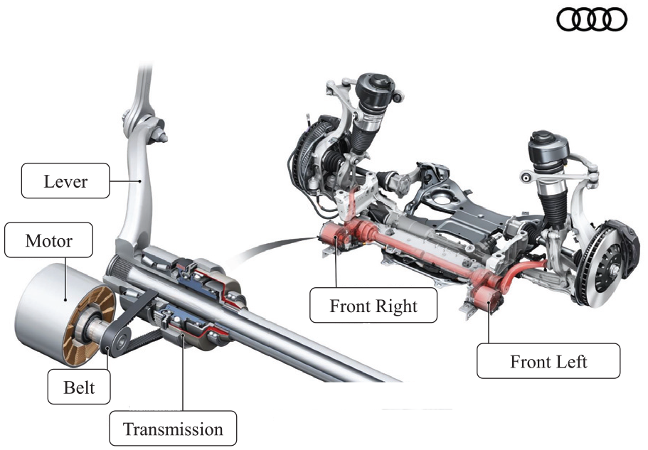
Geared electric motor active suspension system of Audi (2017).
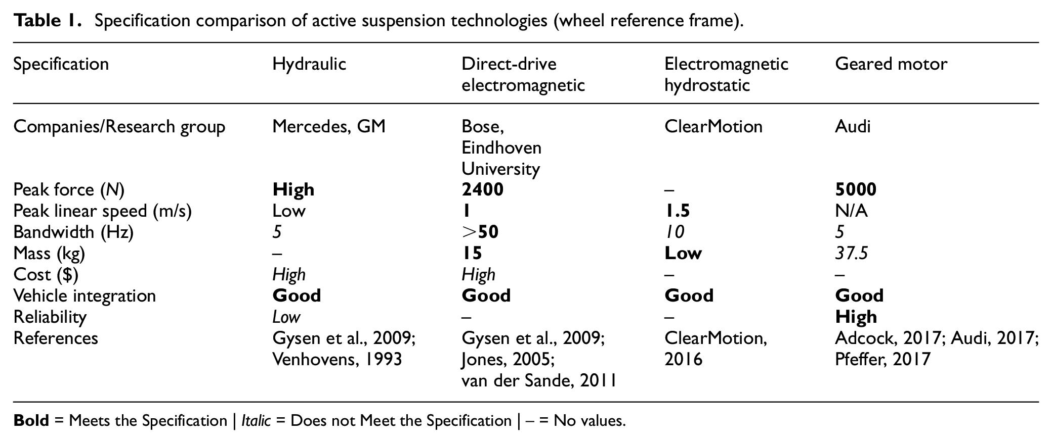
Table 1 presents a summary of either published quantitative values, or inferred qualitative statements evaluating the current active suspension technologies presented with respect to functional requirements. As mentioned, none of these approaches have yet to reach a wide-spread adoption in mass markets since they all present at least one problematic requirement due to intrinsic performance trade-offs. Hydraulic systems are powerful, but relatively slow and expensive. Electromagnetic direct-drive systems are expensive while electromagnetic hydrostatic and electromagnetic geared systems both have bandwidth limitations due to gearing that multiplies the actuator inertia with the square of the gearing ratio.
Specification comparison of active suspension technologies (wheel reference frame).
1.2. MR actuation
Studies have shown that controlled slippage MR clutch actuation has a great potential for active vibration control (Chouinard, 2014). The main reason for such results come from the intrinsic properties of the “slippage” configuration enabled by MR clutches. MR clutches works by transmitting a variable amount of torque between input and output shear surfaces that are separated by interfaces filled with magnetorheological fluid (MRF). The MRF shear force, and thus, the transferred torque, is controlled by varying a magnetic field passing through the fluid. The layer of fluid in MR clutches has the fundamental advantage of decoupling the input inertia of the motor and gearbox from the system’s output, thereby making a low inertia actuator that can be considered as a pure torque source (Figure 5).
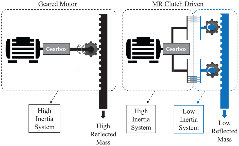
Reflected mass of an electromagnetic geared motor compared to a MR clutch driven system.
A particularly relevant architecture of MR clutches using multiple cylindrical fluid gaps was proposed by Exonetik Inc. (US 2018/0156285). A cutaway view of a 37 N·m version of the clutch is shown in Figure 6. The input (green) and output (blue) rotate independently and are only coupled by MR fluid (white). When current runs through the static coil, a magnetic flux is created, and goes through the shear interface, increasing the base viscosity of the MR fluid, thus transferring torque to the output. As opposed to traditional disk-type clutches, the proposed drum-type configuration enables low-cost fabrication, only has two rotating assemblies, and is tolerant to loose manufacturing tolerances which are essential features for successful mass production.
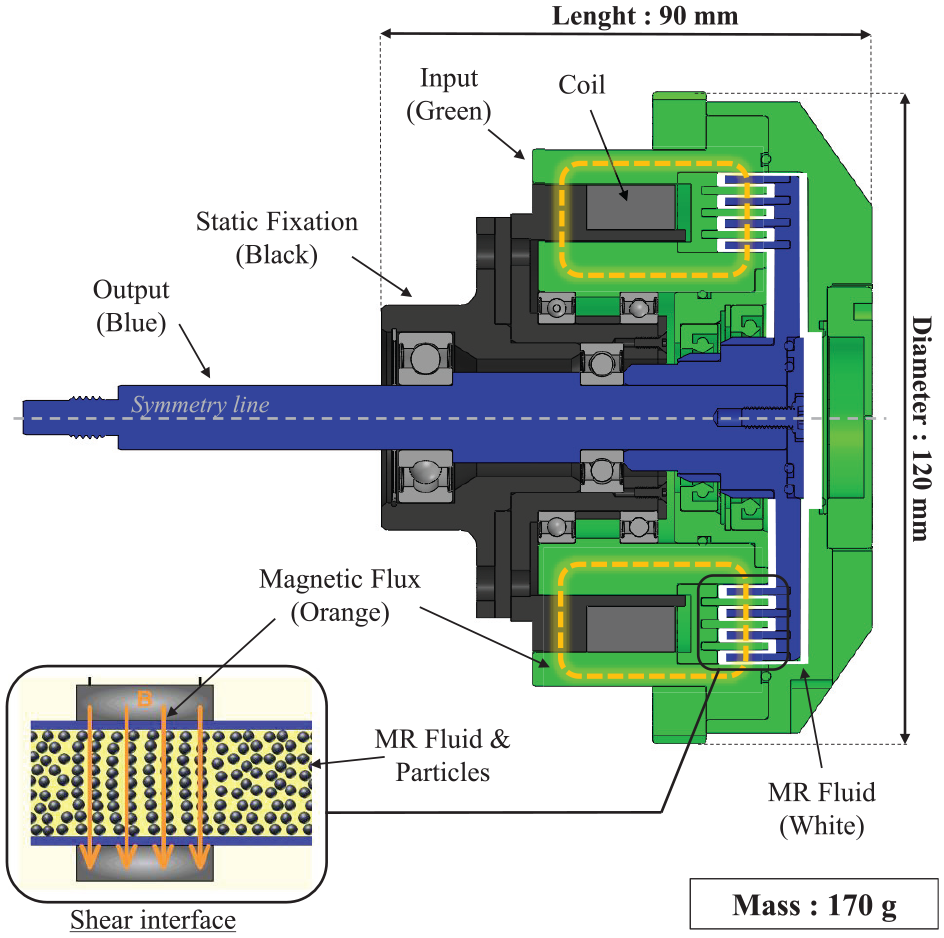
Cut view of Exonetik’s 37 N·m MR clutch.
Experimental demonstrations of a controlled slippage MR actuator was done for a fully active seat suspension showing that the vibration attenuation was two to three times better than a damped or un-damped passive suspension by simply using a high-speed and geared BLDC motor with two MR clutches allowing for a small and inexpensive actuator without trading off dynamic performance (Bégin et al., 2018). The un-optimized active seat prototype developed in that work also showed equal vibration attenuation capabilities to the commercially available Bose Ride system, with only half the weight (Bégin et al., 2018).
It is worth pointing out that active seat suspensions can offer a great improvement in vibration reduction in commercial vehicles, but are not the best option for vehicles aiming to carry multiple passengers comfortably. First, active seat motion is independent from the cabin; the relative motion might be unintuitive at first for occupant when interacting with the steering wheel, pedals, and vehicle controls (e.g. touch screens) in the cabin. Also, active seats only offer suspension control in the vertical axis and cannot compensate roll and pitch vibrations which are big contributors to motion sickness (Diels and Bos, 2016). Furthermore, a vehicle would need as many active seats as passengers in the vehicle, which would increase cost and weight, notably for public transportation such as mini-buses, shuttles, and full size buses. All of these issues could be resolved with fully active vehicle suspension systems, allowing not only vibration control, but also vehicle attitude corrections and ride quality control of the whole vehicle. In the context of this work, active seat actuators operate with forces that are orders of magnitude lower than vehicle suspensions. The potential for controlled slippage MR actuation in full vehicle suspensions applications remains to be studied.
The objective of this paper is to determine if MR actuators can still offer significant advantages over conventional actuation technologies for vibration control when used in scaled-up applications such as automotive active suspensions where power and force levels are multiple orders of magnitudes higher than active seats. As the literature review suggests, this area of research as not yet been investigated, and shows great potential. The selected approach to reach the objective is to develop a prototype for a real-life, practical application and characterize its performance extensively in well-controlled laboratory conditions to understand the strengths and weaknesses of MR actuators in this scaled-up context. To do so, a case study is conducted for the front wheels of a mid-range 5-seater sedan consisting of a BMW 330ci 2001. A set of relevant design requirements for an active suspension actuator for force, linear speed, bandwidth, intrinsic parasitic forces as well as relevant wheel load cases are established with a vehicle in-depth dynamic simulation within Siemens LMS Amesim Imagine Lab software (Amesim) and from on-car accelerometer measurements. Then, a design concept of an active actuator is presented using a high-speed brushless motor to feed a pair of counter-rotating MR clutches providing upward and downward forces on a ball spline supported rack and double pinion mechanism. Finally, a full-scale prototype is fabricated and its performance is characterized experimentally with: (1) a rotary test bench used to characterize the MR clutches and high-speed electric motor independently from the suspension system; and (2) a MTS dynamometer to characterize the performance of the complete suspension system to assess its force, linear speed, bandwidth, and intrinsic parasitic forces.
2. Actuator design
2.1. Design requirements
As seen on Figure 7, the prototype actuator was designed to replace the front stock suspension struts of a 2001 BWM 330ci, referred hereafter as the “test vehicle”. This specific test vehicle was chosen for two main reasons: (1) it represents a typical passenger vehicle reputed to have an excellent suspension with a good balance of performance and comfort, and (2) being rear wheel drive, it offers a large design space at the front since there are no drive shafts in the way to install the active actuator prototype.
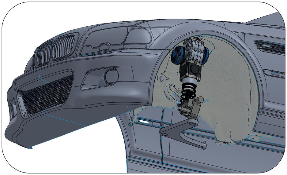
MR actuator CAD in the test vehicle (BMW 330ci).
A detailed 3D model of the vehicle and suspension is built in Amesim including tire performance, suspension geometry characteristics and vehicle 6 DOF body motion with parameters measured on the test vehicle. The Amesim model includes a custom sub-model of a perfect active suspension actuator considered as a pure force source at each corner of the vehicle. Relevant load cases are identified by subjecting the model to a wide set of driving conditions such as bumpy roads, cornering events, pot holes, and curbs.
The test vehicle was instrumented to validate the Amesim model by mounting accelerometers on the rear left unsprung mass, rear left sprung mass (car body), and at the vehicle center of mass. Figure 8 shows the measured and simulated sprung mass vertical acceleration of the vehicle when driving over a bumpy road. The road was modeled in Amesim as a white noise with a specified segment length and amplitude that were adjusted to give the same sprung mass acceleration Power Spectral Density (PSD) amplitude as the experimental measurements. The model predicts well the vehicle acceleration PSD between 0.5 and 25 Hz, and is deemed representative enough to estimate actuator design requirements.
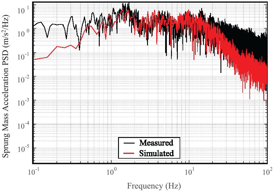
Sprung mass vertical acceleration PSD w/o active suspension (wheel reference frame).
Using the same Amesim car model, the required actuator force and speed profiles are also estimated by simulating the vehicle rolling on an uneven sinusoidal road (1 m long by 0.05 m high bumps). These requirements were estimated as being the amount force and linear speed that are required by the simulated perfect force source to maintain the vehicle at a fixed attitude while no disturbance is being transmitted to the car body. The vehicle speed ranged from 0 to 80 km/h and the vehicle was submitted to braking and cornering conditions to yield longitudinal and lateral accelerations ranging between –1 and 1G. Figure 9 shows a typical simulation result of the forces and speeds in the wheel reference frame, required by the actuators to perfectly compensate vehicle movement while maneuvering on a typical uneven road. The force and speed requirements for this study are then set to be equal or higher than those values. Note that a motion ratio of 0.95 was measured on the vehicle between the wheel and the strut such that a 0.95 N force in the “Wheel Reference Frame” corresponds to 1 N in the “Actuator Reference Frame”.
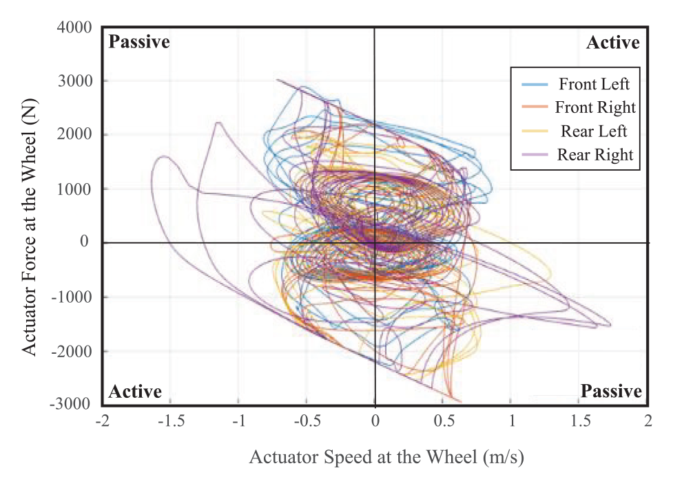
Ideal actuator speed-force diagram (wheel reference frame).
The following design requirements are derived from the simulation results:
Maximum wheel loads: Suspension components on a car represent a fundamental safety system responsible for keeping the wheels attached to the vehicle at any time. The test vehicle uses a Macpherson strut configuration at the front; the MR actuator is thus part of the structural components of the suspension system and must withstand tire loads. The most critical ones are presented in Table 2, and are used for the structural validation of the actuator.
Peak power: A power of 5250 W is required to meet the peak force and the peak speed at the same time.
Peak force: ±3000 N in the Wheel Reference Frame, ±3324 N in the Actuator Reference Frame.
Continuous force: A ±2878 N force in the Actuator Reference Frame is required from the actuator to completely compensate a 1G lateral acceleration corner and is defined as the required maximum continuous force. For this paper, continuous is defined as at least 15 s, which is the required time to complete a 270°, 100 m radius highway ramp taken at 113 km/h (1G lateral load), since it is the most severe sustained load that the actuator will have to compensate.
Vehicle mass-specific force: Not exactly a design requirement, this metric is used to better compare different actuator technologies in regards to the mass of the vehicle it is installed on. It is calculated by dividing the absolute force of one actuator (N) by the mass of the vehicle (kg), which represents 2.2 N/kg for the 1510 kg test vehicle.
Coulomb friction: The Coulomb friction of the actuator must be minimized to avoid poor ride on smooth surfaces (Dixon, 2007). A target of 2% of the actuator’s maximum force is set, which corresponds to ±66 N.
Power-off damping: The system must provide a certain level of damping to retain safety if the actuators are powered-off. The target damping of 1167 Nsm−1 corresponds to a comfort optimized suspension ride-handling parameter of 1 s−1 (Dixon, 2007).
Peak linear speed: ±1.75 m/s peak speed at the wheel translates to ±1.58 m/s at the actuator.
Bandwidth: A blocked output force bandwidth of at least 50 Hz is targeted for the actuator because the negative impacts of vibrations on human health decline quickly over 50 Hz according to the ISO 2631-1 standard. Force control must be retained up to that frequency to maximize the comfort increase potential. The blocked output force bandwidth is defined as the frequency at which the actuator’s blocked output force reaches
Added unsprung mass per corner: The low unsprung mass of a suspension system is very important for the comfort and dynamic abilities of the vehicle (Hrovat, 1988; Ming-chun et al., n.d.). There are no specific mass target for this requirement, the added unsprung mass per corner must be minimized.
Added mass per corner: There are no specific mass target for this requirement. The added mass per corner must be minimized.
MR-fluid life and power consumption: A drawback of the slippage approach is that power is dissipated in the MR-clutch, which in turn, wears the MR-fluid. Studies on active seat systems showed that, for a same vibration attenuation level, the slippage approach is equivalent to a direct drive electromagnetic system in terms of power consumption (Bégin et al., 2018). This suggests that power consumption is not a fundamental limitation but rather an important engineering challenge that must be carefully addressed. In this context and given that real load-cases and user expectations and feedback are non-existent, no design requirements have been set for MR-fluid life and power consumption, which are judged beyond the scope of this feasibility study.
Load cases for the test vehicle (wheel reference frame) modified images from (Creative Commons, 2019).
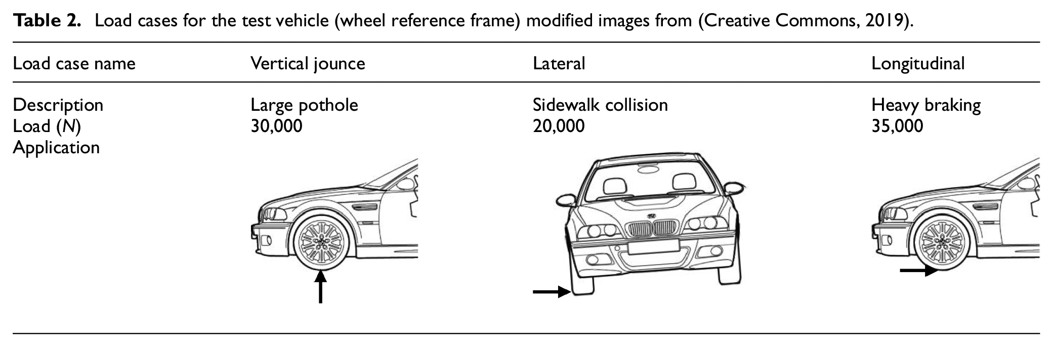
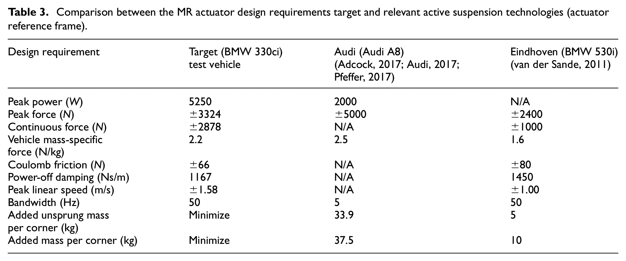
Table 3 summarizes all the design requirement and compares them to the specifications of two commercially viable actuators from Audi and Eindhoven University, each representing technology alternatives of geared motors and direct-drive electromagnetics respectively. The goal for this MR actuator is to aim at all the targeted design requirements without any trade-offs, which means a high peak force, high linear speed, high bandwidth with low parasitic forces, which is not possible with conventional actuator technologies.
Comparison between the MR actuator design requirements target and relevant active suspension technologies (actuator reference frame).
2.2. Proposed actuator design
The working principle of the proposed MR actuator is shown in Figure 10. A single high-speed brushless electric motor drives a double output bevel gearbox splitting the rotary motion in counter-rotating directions. Each output of this gearbox drives the input of a readily available Exonetik 37 N·m MR clutch through a first stage of spur gear ratio. The output of each MR clutch is then connected to the pinion of a rack and double pinions mechanism through a second stage spur gear ratio. The pinions drive the rack in opposing directions, in an antagonistic configuration, to provide full motion authority such that one pinion can pull the wheel up while the other can push the wheel down. A spring is mounted at the actuator’s output to support the weight of the car.
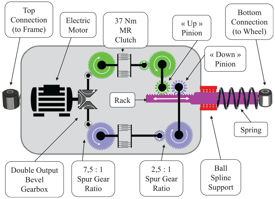
Working principle diagram of the MR actuator.
The MR clutches are controlled individually by varying the electrical current fed to the active clutch, while the inactive clutch has no current and slips freely. This counter rotating system with two opposing pinions allows for a backlash-free system, since each pinion have teeth that are always in contact with the rack in opposing directions.
The MR actuator must be fitted within the wheel arches of the test vehicle in a Macpherson strut configuration. Packaging the actuator presents many spatial challenges, notably because the front struts must allow the front wheels to steer the vehicle. Furthermore, due to the required 140 mm travel, the gear rack must pass through the top connection when the suspension is fully compressed without touching the hood. The solution for this is to install a spherical bearing with an inside diameter of 60 mm in the top connection of the actuator to allow for the compliance of the Macpherson strut suspension system, clearance for the rack motion and allowing rotation of the front wheels. Figure 11 presents a cut view of the actuator, which shows the spherical bearing location, and the clearance it provides. The actuator is a first prototype and is relatively big in size, but yet fits inside the stock vehicle without requiring any modification of the wheel arches, and while keeping the original ride height and suspension travel. The big size is due to using readily available MR clutches. This decision was made to decrease the cost and design time of the prototype. The actuator system could be further reduced in size with future optimization work aiming to use smaller clutches specifically designed for the application.
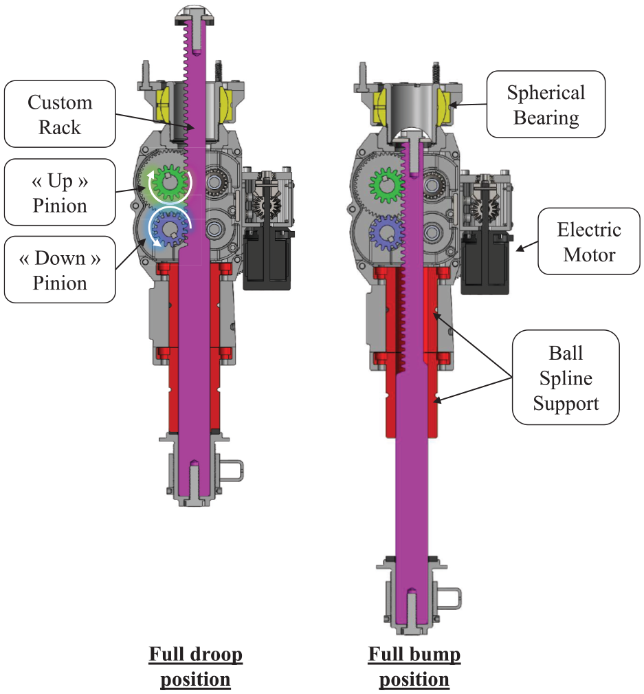
Cut view of the actuator in fully compressed and fully out position (spring removed).
The mechanical design of the proposed actuator is based on a custom rack that is cut by wire EDM directly into a ball spline shaft supported by two consecutive ball spline nuts (Figure 11). Unlike ball screw systems, rack and pinion systems do not have acceleration limitations (Zhang et al., 2016) as well as better efficiency (Stock, 2010); this is especially important since accelerations of up to 40G were recorded during tests when the wheels hit a pothole. Standard rack and pinion systems are usually supported by bushings instead of ball splines, but the moment loads they are subjected to are not as high as the moment loads of an automotive strut. Those high moment loads cause considerable levels of friction that could give the actuator a highly non-linear behavior that would be complicated to actively compensate, hence the use of ball splines. These ball splines are also responsible for keeping the teeth on the rack aligned with both pinions.
Torque is transferred from the clutches to the rack and pinion by using a transfer case which houses a pair of intermediate countershafts (shown in green and blue on Figure 12(a)). The transfer case is also used as a structural element to connect the clutches, motor unit, top connection and ball spline unit (Figure 12(b)). The transfer case is symmetric, with two 6061-T6 aluminum machined half-casings that hold all the components together. All gears are made with carburized gears (QTC KSMGA series gears) providing high strength and abrasion resistance. The gears are arranged around the rack to be as compact as possible within the casing, with a first reduction ratio between the splitter gearbox and the clutches of 7.5:1 and a second reduction ratio between the clutch output and rack pinions of 2.5:1. Both these ratios were chosen such that the functional requirement of maximum continuous force of ±2878 N (Table 3) is set below the maximum continuous torque of the motor, and the maximum continuous drive current of the clutches, while still being able to reach a peak force of at least ±3324 N (Table 3), and all this while being constrained to use Exonetik’s 37 N·m MR-clutches. The actuator is powered by a KDE Direct BLDC electric motor operating on a voltage of 59.2 V to meet the actuator speed requirement.
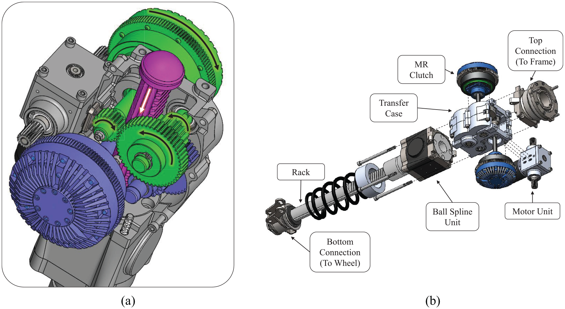
(a) Inside view of the transfer case and gearing and (b) exploded view of the main sub-assemblies of the actuator.
The actuator’s key technical characteristics are presented in Table 4, and the fully assembled prototype is shown in Figure 13.
MR actuator key characteristics.
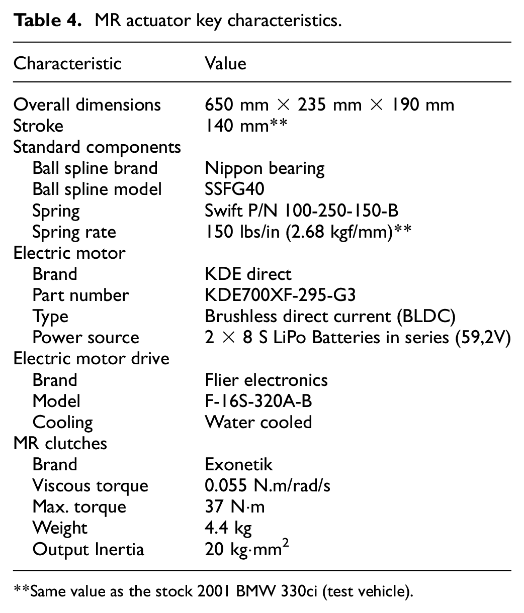
Same value as the stock 2001 BMW 330ci (test vehicle).
MR actuator assembled prototype.
2.3. Structural validation
A Macpherson strut can be designed in two different configurations, which are commonly referred as “Standard” or “Inverted” (Figure 14). For this MR actuator, an inverted configuration is used to minimize the unsprung mass since the top section of the actuator is three times heavier than the bottom section. This configuration is also easier to package in the wheel arches. However, the downside is that a much bigger rod is needed to resist the moment loads created by the wheel loads.
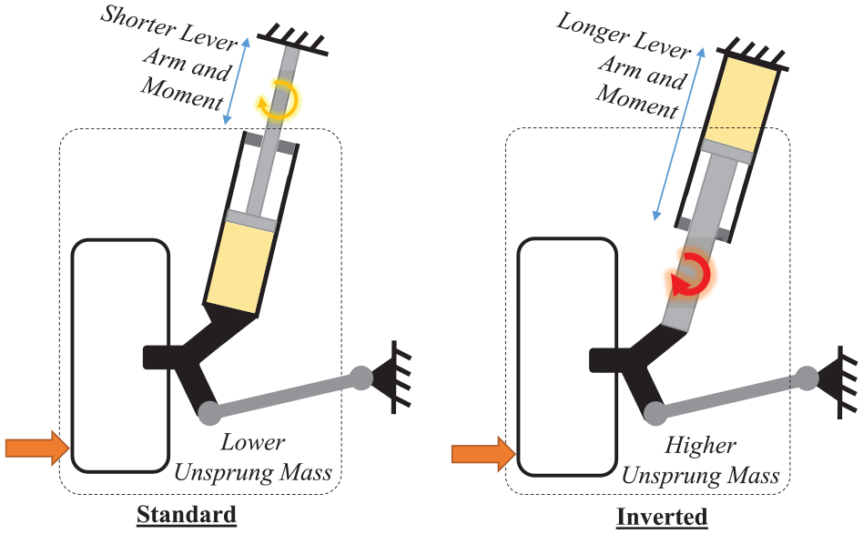
Standard upright versus inverted configuration of a Macpherson strut.
FEA structural analyses were performed to validate the actuator would be able to withstand all the moment loads created by the wheel load cases presented in Table 2, as well as the loads that come from the motor and clutches. The results showed that all stresses during the most severe load cases (low occurrence events) are below yield, and that the transfer case was the weakest component with a safety factor of 1.3 on the yield stress for a full droop lateral load. Fatigue studies on critical parts showed that they had a predicted infinite life. The FEA structural validations on the MR actuator thus showed no safety issues.
3. Experimental results
3.1. Rotary test bench
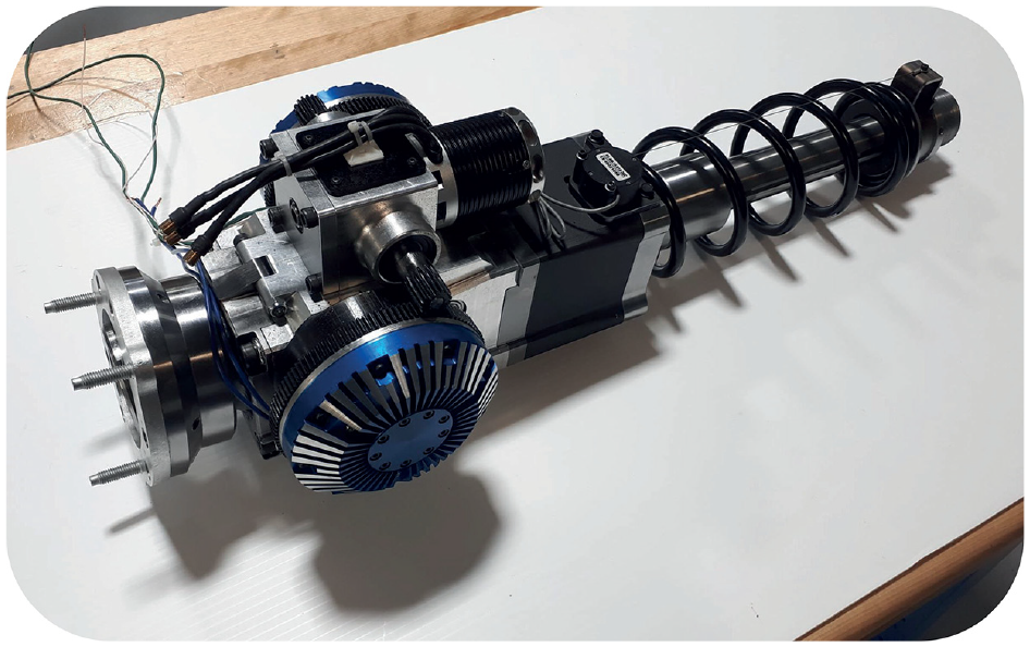
To validate performance specifications, a rotary test bench measures the individual performance of the most critical components of the system, which are the 37 N·m Exonetik MR clutch and the KDE700XF-295-G3 high-speed electric motor (Figure 15). The test bench can provide any combination of clutch torque and rotational speeds of both the clutch input and output by varying the current supplied to the clutch (24 V, 0–20 A power supply), the power supplied to the motor (68 V, 0–125 A, Sorensen DHP80-125 power supply) and the friction on a disc brake mounted on the clutch output. Torque is measured with a 200 lbf load cell attached to a torque arm connected to the brake caliper.
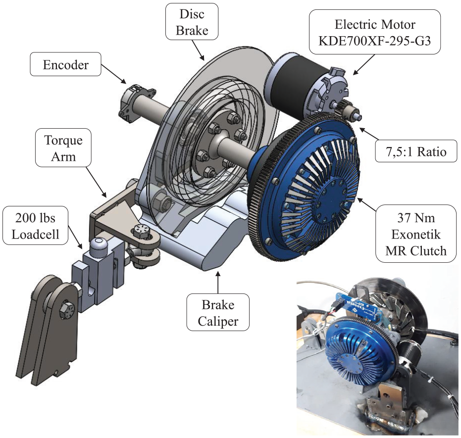
Test bench for MR clutch and motor characterization.
Results from MR clutch characterization indicate an off-state torque of 0.0031 N·ms/Rad (Figure 16(a)), a maximum torque of 37 N·m at 14 A with a slip speed of 100 rad/s (Figure 16(b)), and a blocked output force bandwidth of 7 Hz evaluated by the force amplitude drop (Figure 16(c)).
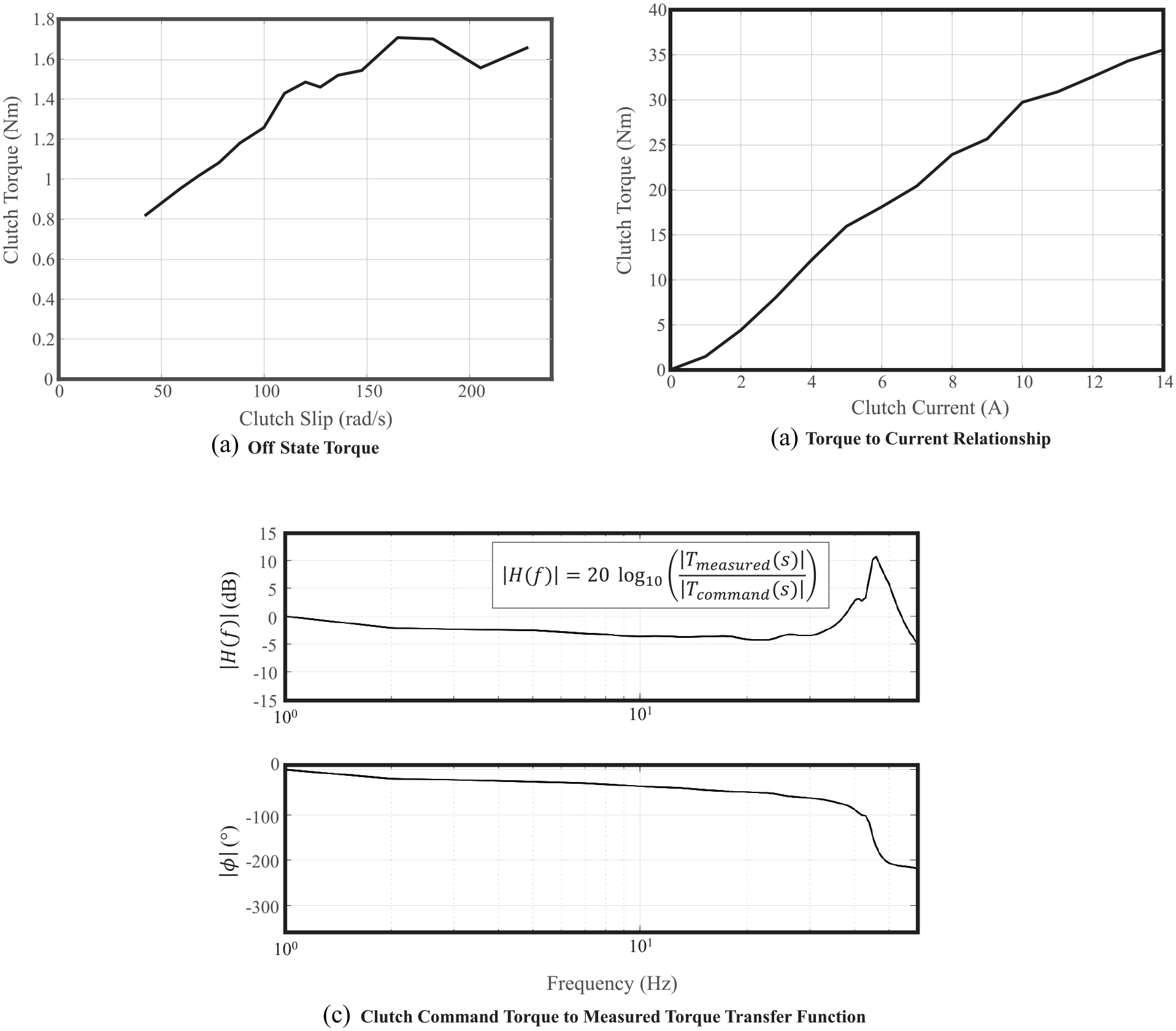
Exonetik 37 N·m MR clutch characterization results.
3.1.1. Peak power
Figure 17 shows the KDE700XF-295-G3 electric motor’s performance. The maximum measured continuous power is 6.5 kW at 16500 RPM, which meets the 5.25 kW requirement. The maximum measured continuous torque is 3.8 N·m from 350 to 16,500 RPM, which corresponds to a 3800 N force at up to 1.73 m/s in the Actuator Reference Frame. The motor can be overdriven for 2 s bursts at up to 250 A, potentially doubling its torque output. The motor’s power supply was limited to 125 A, but the system on the test vehicle will use lithium-polymer batteries that can provide 250 A.
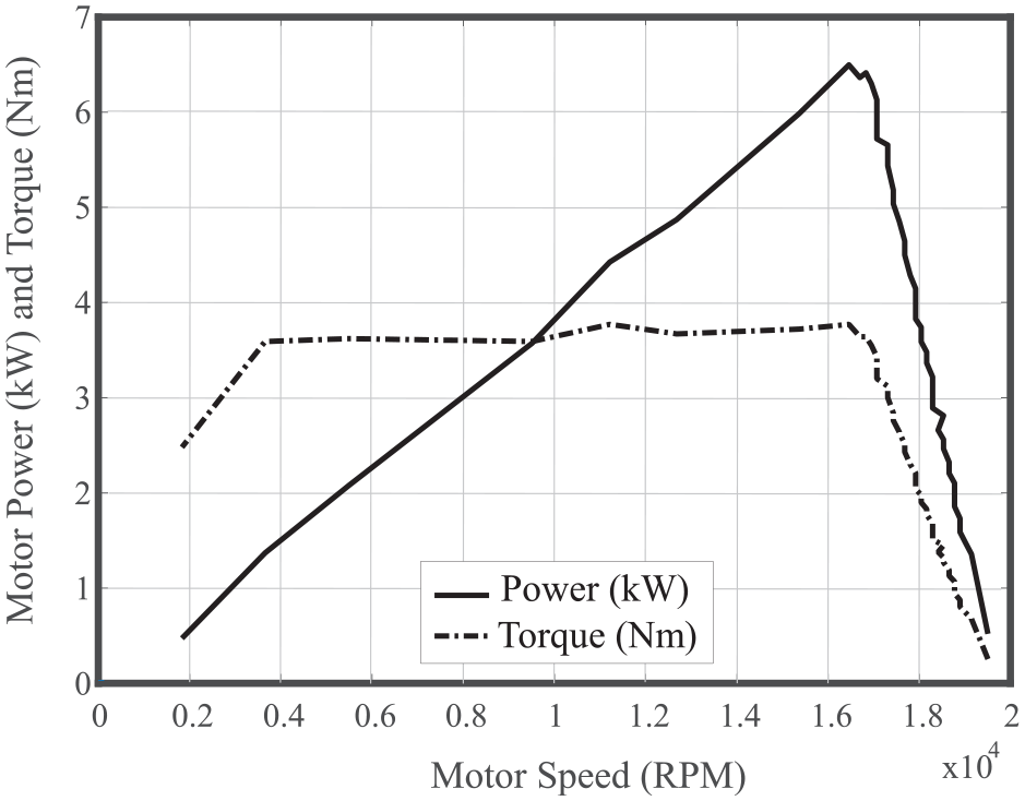
KDE700XF-295-G3 electric motor power and torque curve.
3.2. Linear dynamometer tests
The performance of the complete strut actuator is measured on an MTS 322-31 damper test rig that produces forces of up to 250 kN and speeds of up to 0.2 m/s. The actuator is mounted vertically and the top is connected to a 300 kN load cell as shown in Figure 18.
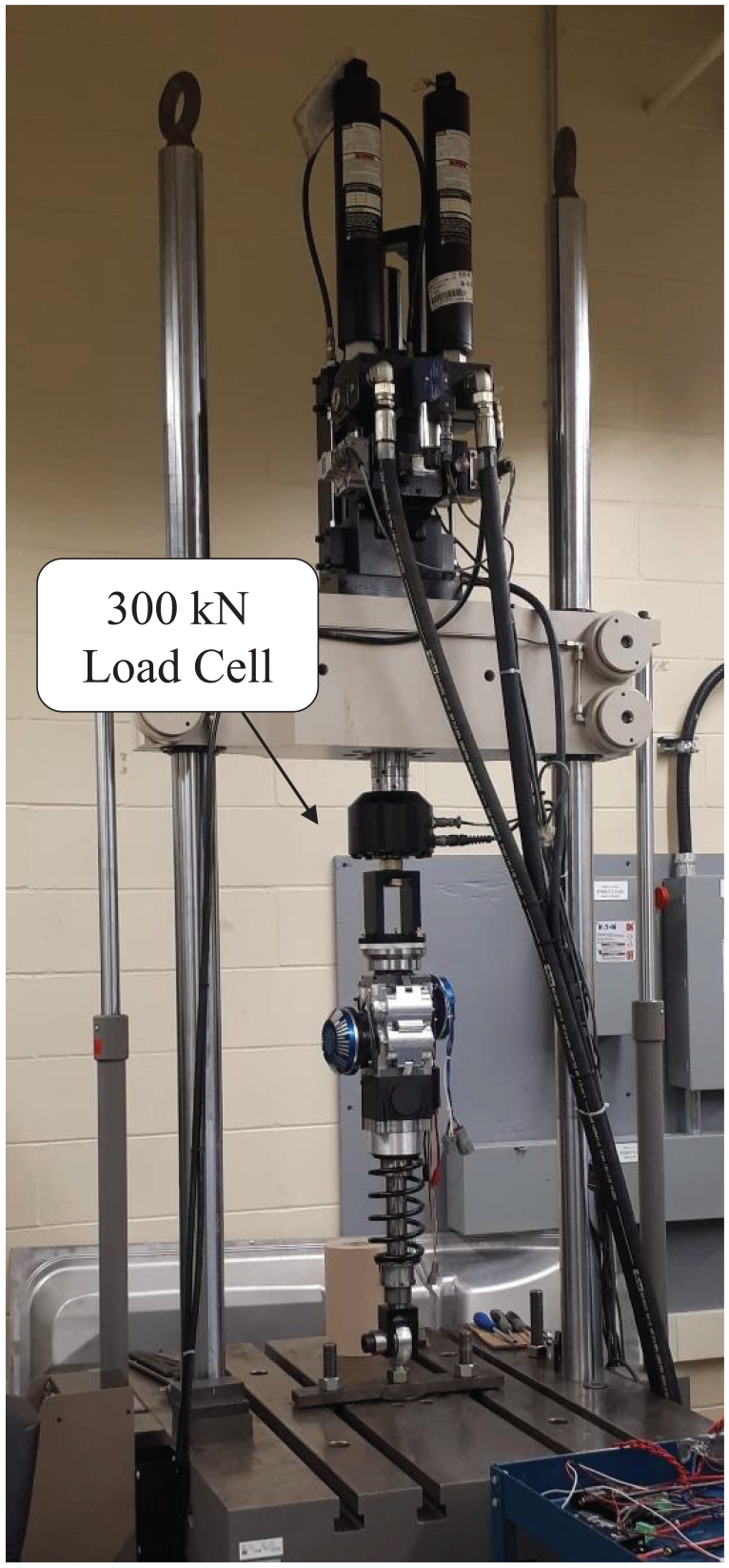
MR actuator on MTS 322-31 test rig.
3.2.1. Peak, continuous and vehicle mass-specific forces
The actuator force to current relationship was measured on the MTS machine and is shown in Figure 19. A maximum force of ±5300 N is reached and is limited by the electric motor torque output, which means a 3.5 N/kg mass-specific force for the test vehicle. A maximum force hysteresis of 5% is measured at 0.5 Hz using a sawtooth wave current command of 0 A to 10 A to 0 A with a 1 s ramp up time and a 1 s ramp down time (Figure 20). The hysteresis being very small for the application, no extra tests were carried. The hysteresis does not only occur at 0.5 Hz, but at all frequencies. A test was arbitrarily carried at 0.5 Hz to show the force hysteresis of the actuator. It was also verified that the actuator can sustain a continuous force of ±2878 N for 15 s without overheating or failure of any components.
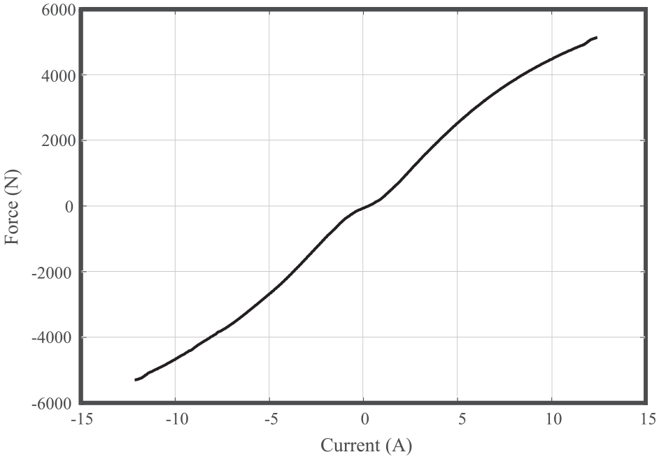
MR actuator force to current relationship (1 Hz) (actuator reference frame).
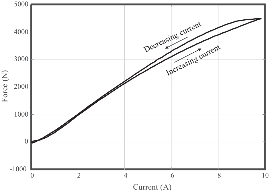
MR actuator force hysteresis (0.5 Hz) (actuator reference frame).
3.2.2. Coulomb friction and power-off damping
Actuator parasitic forces are measured by imposing multiple positive and negative speed commands with the MTS machine while the actuator is inactivated. Figure 21 shows the resulting forces as a function of speed, with the force due to spring compression subtracted. A 36 N Coulomb friction and a linear damping coefficient of 638 Ns/m approximate the parasitic forces of the actuator. The Coulomb friction is negligible (0.7 %) compared with the maximum force produced by the actuator, and on par with conventional dampers friction levels (Dixon, 2007). The damping coefficient is deemed high enough to retain vehicle stability when the active suspension is powered off because the vehicle’s damping coefficient produces a ride handling parameter of 0.8 s−1. That value is only 21% below the ideal ride handling parameter for comfort in a passenger car (Dixon, 2007), and is representative of the viscous torque of the MR clutches that were used for this application. This value could be easily optimized in further prototypes.
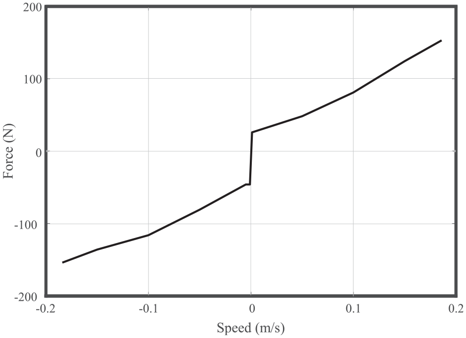
MR actuator parasitic force (actuator reference frame).
3.2.3. Peak linear speed
Another test setup was required to validate the actuator’s maximum linear speed since the maximum speed of the MTS machine (0.2 m/s) is insufficient. The actuator was grounded horizontally on a table and the spring was removed, leaving the rod free to move (Figure 22). Linear speed was measured using an Unimeasure FX-HM-15-N1S-2QC analog position transducer. The motor throttle was set to 100%, a –5000 N force command was sent for 70 ms to retract the actuator rod, followed by a 10 ms +5000 N force command to prevent the rod from hitting the top bump stop. Figure 23 shows the actuator speed throughout the test, and shows maximum peak linear speed of 1.97 m/s.
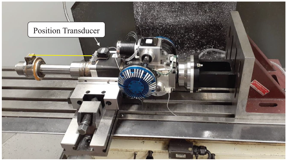
MR actuator peak linear speed test setup.
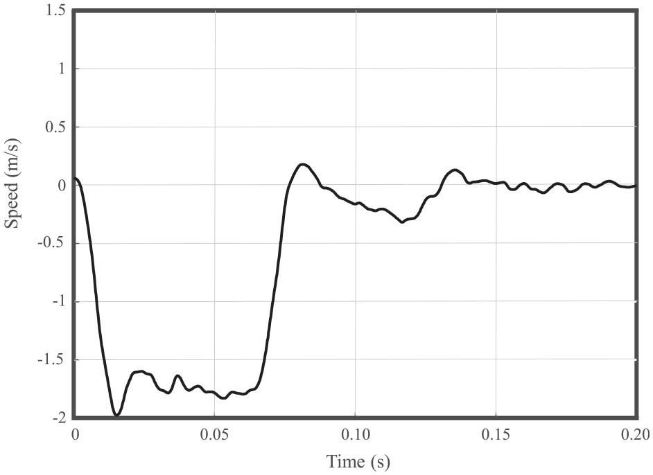
MR actuator linear speed (actuator reference frame).
3.2.4. Bandwidth
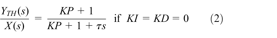
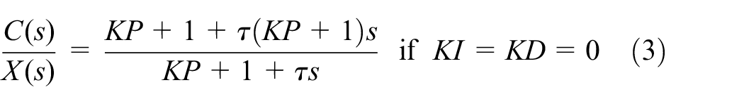
The bandwidth was evaluated using the MTS 322-31 (Figure 18) which was locked in place to block the output of the MR actuator. A ±1000 N, 0.1–200 Hz logarithmic chirp force command is sent to the actuator to evaluate the controller’s performance. Initial tests showed a blocked output open-loop force bandwidth of 9.4 Hz caused by a force amplitude drop, without significant phase lag. This bandwidth value is comparable to other high-torque MR clutches in the 10 N·m range (Bégin et al., 2018; Chouinard, 2014). Fortunately, because the MR system is transparent and behaves linearly without phase lag due to backlash or friction effects, it is possible to use a model-referenced feedforward controller to compensate the force amplitude decay with significant benefits without any stability issues. The proposed feed-forward controller is depicted in Figure 24 and equation (1), and represents the controller’s transfer function between the command X(s) and the theoretical actuator force output YTH(s) modeled as a first order system. If the system’s first order model describes well the actuator, the actuator theoretical force YTH(s) should approximate the real actuator force Y(s) and the amplitude decay between the desired force and real force should easily be compensated. Using only a proportional gain works well in practice and the stability of the controller is guaranteed if
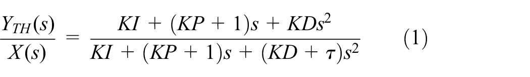
The feedforward controller was implemented on the actuator using a gain of KP = 0.8 and the following system model parameters: a 9.4 Hz first order lag (τ = 0.0169 s). Figure 25 shows that the controller increased the actuator’s blocked output bandwidth by an order of magnitude to 92 Hz, where the phase lag reaches –135°. Further increasing KP yields a higher bandwidth, but results in a positive amplitude gain between 10 and 50 Hz due to an internal mode of the clutch current controller. At 125 Hz, the system hit a major phase shift due to a mechanical resonance. The cause of the resonance is most likely due to the first torsional mode of the clutch output shaft, but remains to be investigated. A 92 Hz blocked output bandwidth largely meets the 50 Hz requirement, so KP = 0.8 was used for all the tests. Also, the mechanical resonance at 125 Hz is high enough not to be excited by the road (Loprencipe and Zoccali, 2017) and therefore should not cause vibration issues.
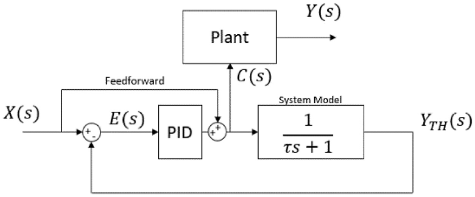
Model-referenced feedforward controller.
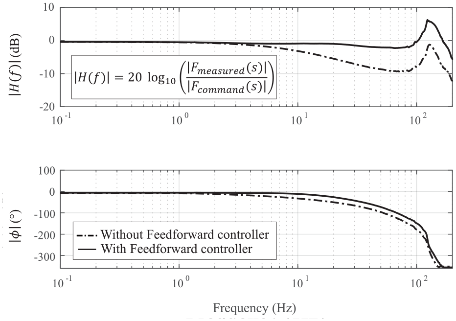
MR actuator blocked output force bandwidth (actuator reference frame).
3.3. Actuator mass validations
3.3.1. Added unsprung mass and mass (per corner)
The unsprung and total mass of the MR actuator’s final assembled prototype were measured and compared to the stock strut and suspension mass of the test vehicle (Figure 26). Compared with the stock strut, the MR actuator increased the total mass by 14 kg, and the unsprung mass by 3 kg. The prototype presented in this study was designed with the goal of minimizing the added mass, but was not optimized for mass (recall that the MR clutches were not originally designed for an automotive suspension application and their mass is not optimized). Further prototype versions of this technology have the potential to be much lighter.
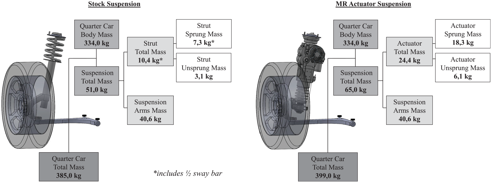
Detailed mass comparison of stock suspension versus MR actuator suspension.
3.4. Experimental results summary
Table 5 shows that the actuator surpasses all the intended design requirements except for power-off damping, which fortunately is easily tunable by tuning the MR clutch design parameters. As it was done for the establishment of design specifications (Table 3), the comparison is also made with other relevant active suspension technologies.
Target versus measured actuator performance (actuator reference frame).
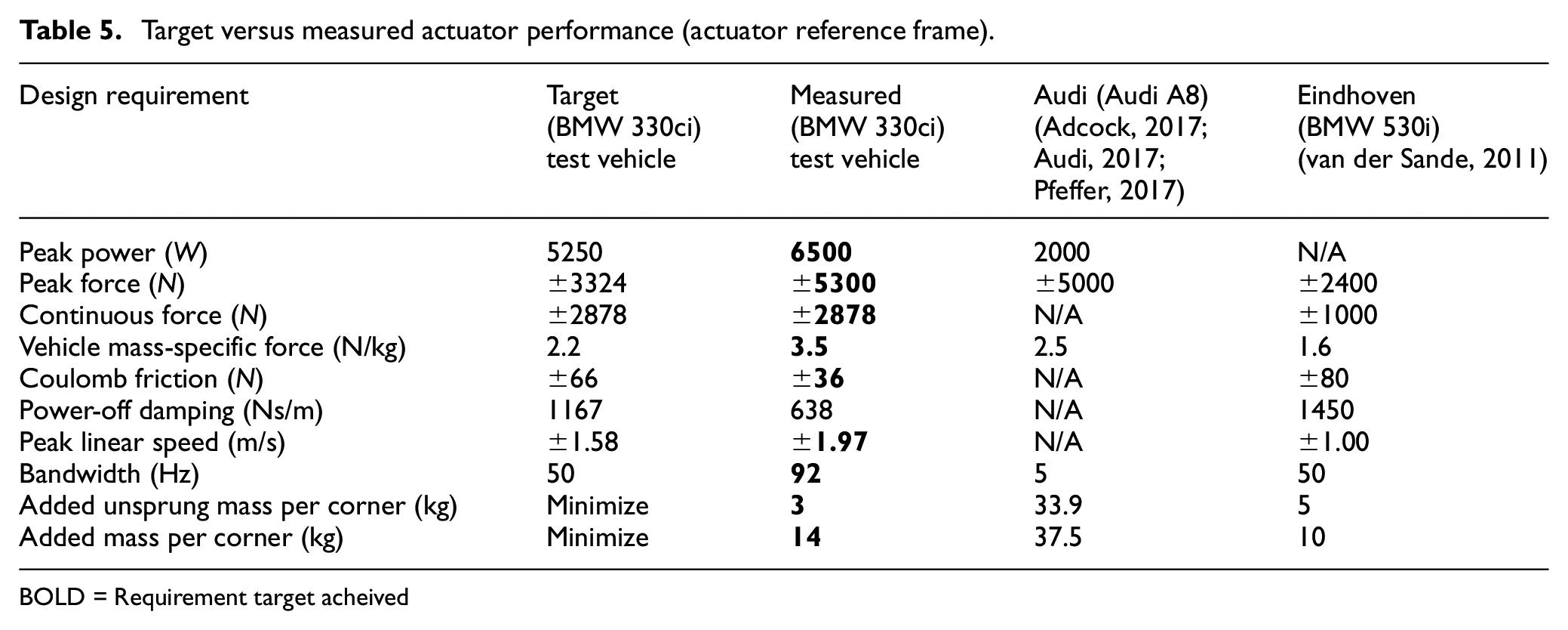
BOLD = Requirement target acheived
Results from the experimental assessment confirm that the MR technology is simultaneously superior both in terms of maximum force and of maximum bandwidth, with negligible parasitic forces and added unsprung mass when compared to other relevant technologies such as geared motors and direct-drive electromagnetics. These results reveal that MR actuators have significant advantages over conventional actuation technologies for vibration control even when scaled-up to the power and forces required by automotive active suspension applications.
4. Conclusion
This paper studied the potential of controlled slippage MR clutches in an uninvestigated and scaled-up vibration control application consisting of automotive active suspensions to cancel road vibrations and correct vehicle attitude during maneuvers. An MR strut actuator prototype was designed and built to assess its capabilities in terms of force, linear speed, bandwidth and parasitic forces. The prototype was designed to replace the stock front Macpherson struts of a 2001 BMW 330ci. Based on a full car model built in Siemens Amesim and validated through instrumentation of a test vehicle, meaningful design requirements for an active suspension were defined and used for the design of the MR actuator. The proposed actuator uses a high-speed brushless motor to feed a pair of readily available counter-rotating MR clutches to provide upward and downward forces on a ball spline supported rack and double pinion mechanism.
An experimental characterization was conducted to verify each design requirement and identify the strengths and weaknesses of the MR actuator approach. A rotary test bench was used to characterize the performance of the MR clutches and high-speed electric motor. The MR clutch showed an off-state torque of 0.0031 N·ms/Rad, a maximum torque of 37 N·m and a blocked output force bandwidth of 7 Hz, while the electric motor showed maximum continuous power of 6.5 kW, and a continuous torque of 3.8 N·m from 350 to 16500 RPM. When installed on an MTS linear dynamometer rig, the actuator was able to output a peak force of ±5300 N, a peak linear speed of ±1.97 m/s and a blocked output force bandwidth of 92 Hz using an input-shaping filter. Compared with the stock suspension strut, the MR actuator has an added mass of 14 kg, with an added unsprung mass of 3 kg.
Results show that MR actuation surpasses all intended meaningful design requirements excepted for power-off damping (which is of secondary order importance). Hence, it can be concluded that MR slippage actuation is highly promising for vibration control applications in scaled-up conditions such as automotive active suspension.
When compared to other relevant technologies such as geared motors and direct-drive electromagnetics, MR actuators still have significant advantages when scaled-up for the power and forces required by automotive active suspension applications. The slippage approach is still emerging and has many challenges remaining to be studied such as MR-fluid life and actuator power consumption. Since MR-fluids have made their way into commercial semi-active suspensions, it is expected that their fully active versions have the potential to do it as well.
Future work will integrate multiple linear actuator prototypes on the test vehicle for an on-road experimental characterization. The rolling testbed will investigate motion controllers specific to MR-actuator characteristics. In particular, advanced control strategies will be developed to simultaneously control both clutch torque and motor speed to minimize power consumption and MR-fluid wear.
Footnotes
Acknowledgements
The authors would like to thank SRP Control Systems ltd., KDE Direct, Advanced Motion Control, and Maxx amps for the quality hardware. The authors especially thank Mathieu Lamy, John Bass, and Dr. Patrick Chouinard for their support.
Declaration of conflicting interests
The author(s) declared no potential conflicts of interest with respect to the research, authorship, and/or publication of this article.
Funding
The author(s) disclosed receipt of the following financial support for the research, authorship, and/or publication of this article: The authors would like to thank Exonetik Inc. for their technical and financial support, as well as MITACS, FRQNT Master’s Research Scholarship, Canada Research Chair and NSERC Discovery Grants Program for their financial support.