
Abstract
This work was carried out in the framework of a funded project aimed at evaluating the feasibility of an ad hoc clutch for the disengagement an auxiliary device, i.e. the vacuum pump used with the powerbrake in diesel engine vehicles, when its operation is not required. In this way it is possible to improve the overall vehicle efficiency. Strict design specifications were defined with reference to available room, torque transmission, absence of axial loads and fail-safe operation. A magnetorheological clutch with permanent magnets was conceived to fulfil the technical requirements. Different clutch geometries were compared with particular reference to the fail-safe operation and torque capabilities. After an iterative procedure, in which both mechanical design and magnetic field analyses were considered, the most promising solution was defined and a prototype was built and tested. A four-pole sliding permanent magnet was adopted to generate the magnetic field. The experimental results validated the developed models and demonstrated the feasibility developed models and demonstrate the feasibility of the proposed solution. A principle for the automatic clutch actuation is also presented.
Keywords
Introduction
Magnetorheological fluids (MRFs) appear particularly convenient for automatic clutch applications due to their capability of increasing their shear strength, in a few milliseconds (Bossis et al., 2002), when subjected to a magnetic field, and behaving as viscous fluids when the magnetic field is removed. They have been investigated since the late 1940s and are now produced by a few manufacturers around the world who also provide their main characteristics.
MRFs are employed in different operating modes (Olabi and Grunwald, 2007) depending on the application: in particular, in clutches and brakes the shear mode is exploited. The first applications of MRFs were focused on clutches (Rabinow, 1948) and the magnetic field was generated by coils. However, MRFs have been widely considered only since the mid-1990s mainly due to control systems requirements and the availability of commercial fluids. In addition to being controllable, they have the advantage, with respect to conventional clutches, of not requiring axial loading and the absence of wear. Usually, magnetorheological (MR) clutches have multi-disc (Bansbach, 1998; Gopalswamy and Jones, 1998; Kavlicoglu et al., 2007; Karakoc et al., 2008) or drum-type geometry (Lee et al., 2000; Neelakantan and Washington, 2005) with a response time (i.e. the time to reach the steady torque) of the order of magnitude of 10−1 s and a maximum torque that in some applications goes beyond 10 Nm. MRF clutches gained interest also in the automotive field: a high-torque limited slip differential based on MRFs was proposed by Kavlicoglu et al. (2006, 2007). MR brakes have also been proposed by Carlson (2001), Li and Du (2003), Bica (2004) and Karakoc et al. (2008); in those papers the limits of the maximum achievable torques and the problem of frictional heating are discussed.
All of the above-cited references make use of coils which is definitely more common than the use of permanent magnets (PMs), rarely mentioned in the literature. The use of coils, indeed, makes the actuation and control easier even though fail-safe problems have to be addressed. An MR clutch, which may include a PM, was proposed in a patent (Steinwender, 2012) but no specific investigation was presented. Recently an MR brake with PM applied to a safety escape device was proposed by Yang et al. (2013). This represents the only documented study of a PM MR brake the authors know of; however, a comparison with this system cannot be made because the application requirements and operating conditions are completely different from those of the present work.
This paper focuses on the design of a compact MR clutch with PMs. The clutch was envisaged to disengage the power brake vacuum pump, when not needed, from a diesel engine, in order to reduce fuel consumption and emissions (Bucchi et al., 2013d). When required, the clutch has to keep engaged, in order to assure a proper operation of the vacuum pump and avoid slip. A simple ON–OFF operation is then required for this application, with no control requirements. Indeed, any magnet position control would cause a decrease of transmitted torque that would produce clutch slip, power dissipation and self-heating.
Even if this application requires a very limited torque compared with the usual automotive transmission clutches and brakes, the main difficulties which were encountered during the design phase were the achievement of sufficient torque levels within strict size constraints.
The novelty of the proposed MR device is the actual automotive application with strict design torque and volume specifications to be satisfied simultaneously, with the employment of a PM (Armenio et al., 2011) and its pneumatic actuation. Compared with MR clutches with coils, although the maximum torque is not controllable and the response time is longer, it is fail-safe because the magnetic field does not depend on current and does not require energy for actuation.
A preliminary experimental characterization of the developed prototype was presented by Bucchi et al. (2012), while the influence of geometric parameters on the MRF magnetization and, in turn, on the clutch performance was discussed by Bucchi et al. (2013a), with the aid of two newly introduced performance indices.
In this paper, after having defined the technical specification for the envisaged application, the selection of the proper geometry is discussed and the design of the clutch analysed. A feasibility study of the envisaged actuation system is also included. Finally, in order to validate the design, the torque characteristics in the ON and OFF state, obtained by a purposely developed experimental apparatus, are reported and compared with those expected on the basis of simulation.
Clutch design
Design requirements
The design requirements for the clutch are given in Table 1. The nominal torque (ON condition) necessary to drive the vacuum pump is about 1 Nm. A somewhat higher torque, i.e. 2.5 Nm, may be requested at vehicle start-up, for short times, in the case of low temperatures (due to the high viscosity of the lubricant in the vacuum pump, which causes an increase of the absorbed torque). A model of the clutch, based on neural networks, capable of accounting for clutch slip during these transients is presented by Bucchi et al. (2013b). On the other side, the torque in the disengaged (OFF) condition must be as low as possible, in order to minimize losses.
Design specifications.
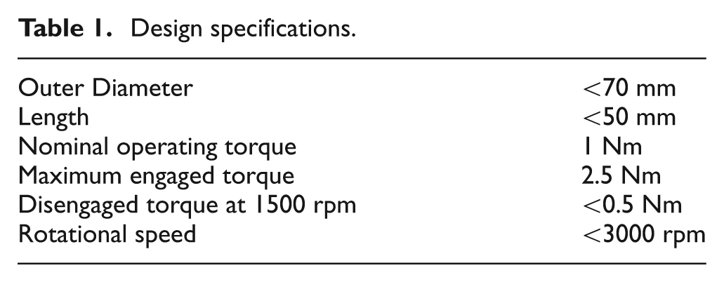
Additional required specifications were the absence of any axial load on the input or output shaft, a fail-safe operation in the case of electric failure (e.g. due to exhausted batteries) and strict size constraints, due to the small volume available for the device.
For the foreseen application the clutch should be directly coupled with the camshaft, therefore the rotating speed limit in Table 1 is referred to 6000 rpm of the vehicle engine. The expected operating temperatures and service life are those typical for automotive components (i.e. −20 °C to 100 °C and 1 year maintenance program).
Preliminary geometry selection
MRFs exhibit a nonlinear dependence of the magnetorheological shear stress on the shear rate
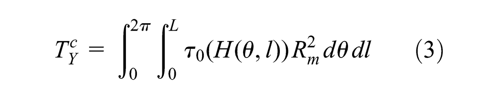
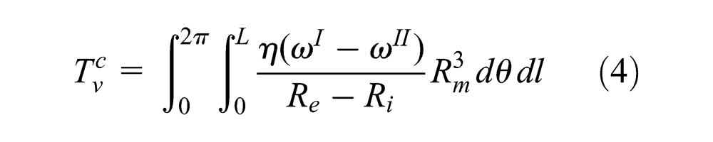
In the initial design step, in order to define an appropriate clutch geometry, the configurations shown in Figure 1 were examined, having defined a design room, based on the size limits given in Table 1. In order to estimate the torque capabilities, each configuration was assumed to be made of a combination of single plane or single cylindrical gaps (Figure 2). For the elementary plane gap the yield and viscous torques can be computed as follows:
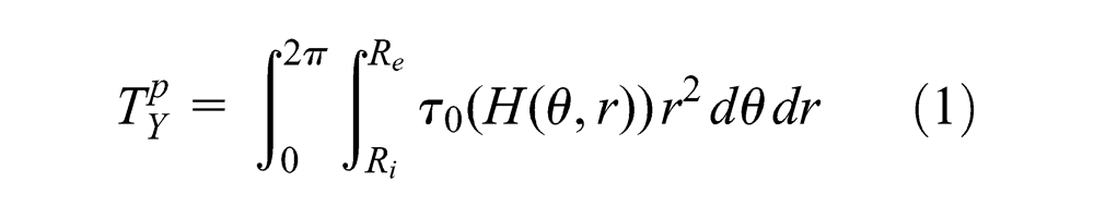
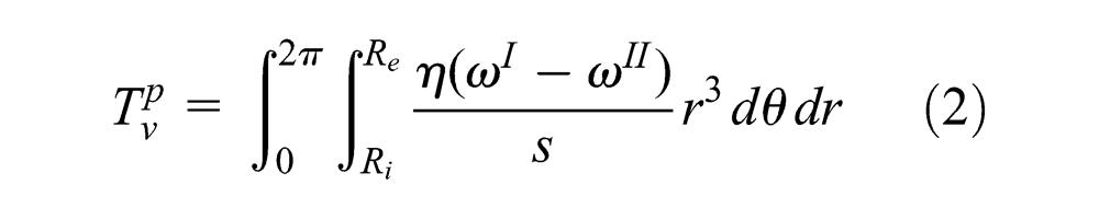
where the geometrical parameters are defined in Figure 2 and
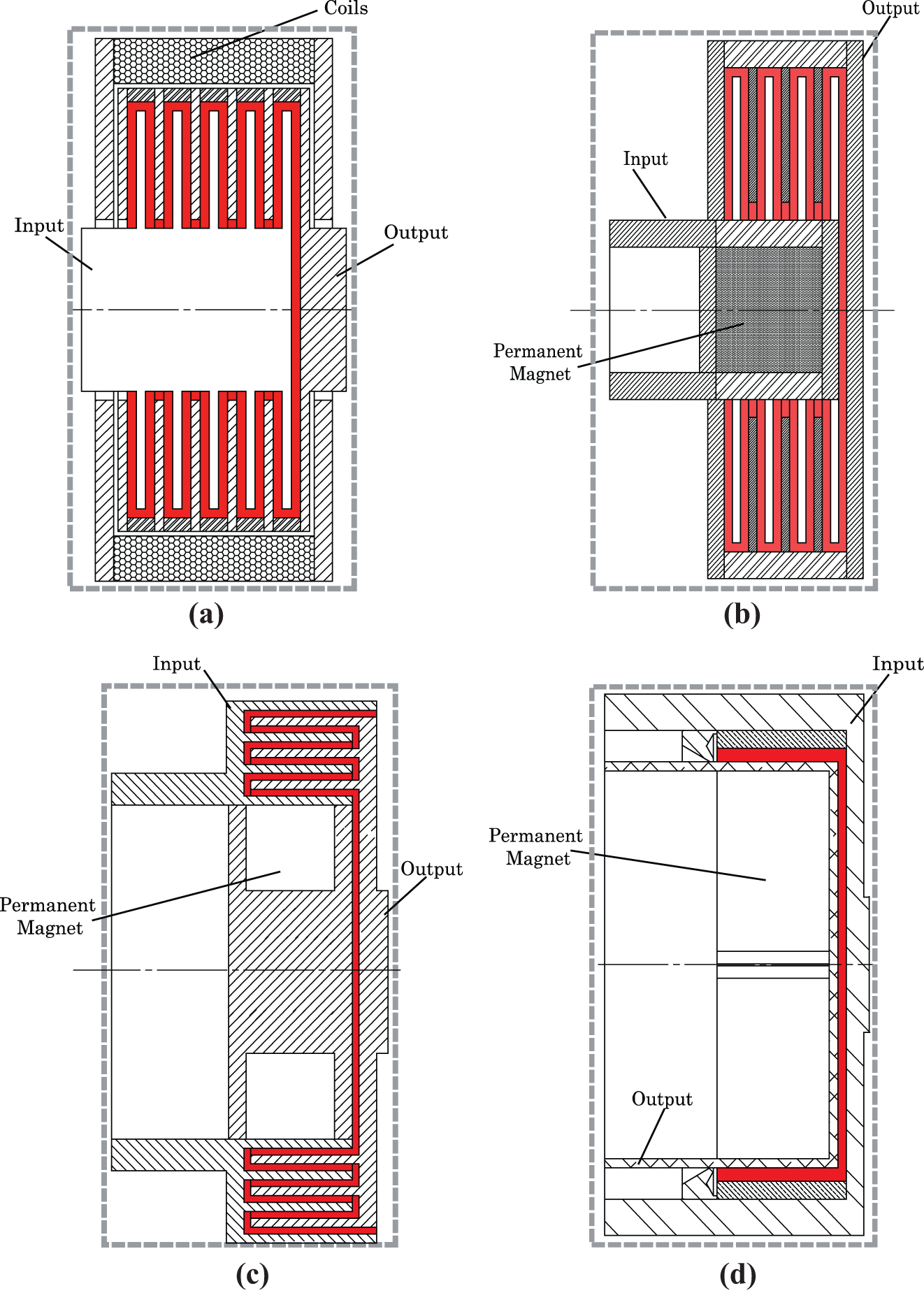
Analyzed clutch geometries: (a) multi-disc with coils; (b) multi-disc with PM; (c) multi-cylinder with PM; (d) hybrid (disc–cylinder) geometry with PM.
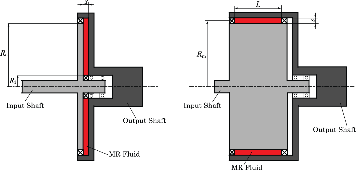
Plane and cylindrical geometry.
The magnetic field distribution, necessary for evaluating the yield stress
With reference to the multi-disc scheme (Figure 1(a)) with coils, the torque is transmitted by five thin discs. The coils were assumed to be placed along an external ring and subjected to the maximum endurable direct current. Magnetic FE simulations showed that the magnetic flux density along the fluid was almost constant but very low (
Multi-disc with coils.
The alternative multi-disc configuration, in which the magnetic field is provided by an internal PM, is presented in Figure 1(b). In this case, due to the fact that the discs extend to the maximum clutch diameter, a considerable increase of the transmitted torque can be achieved (Figure 4). In this solution the magnet should be moved axially to obtain the engaged/disengaged operation and, therefore, only half of the total volume could be dedicated to the discs. As a consequence, the total path of the magnetic field is shorter, and as a result, the magnetic field intensity through the fluid is higher with respect to the previous solution, even if the fluid still appeared to be far from saturation. In this case, the viscous torque is higher than that of the previous solution because of the larger average diameter of the fluid gap.
Multi-disc with a PM.
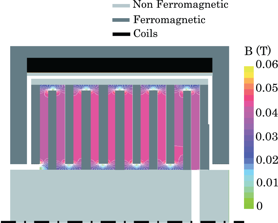
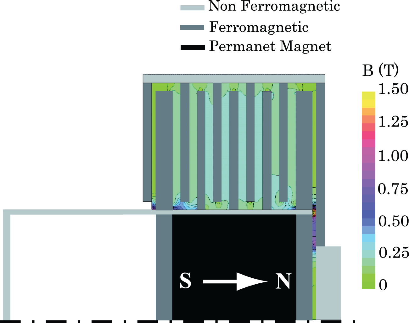
In the multi-cylindrical geometry shown in Figure 1(c), a PM with radial magnetization, which can be moved axially, was considered. Also in this case only half of the total volume can be used for the cylinders. Magnetic simulations revealed that only the first cylindrical gap, the one closer to the magnet, was sufficiently magnetized, whereas the external ones were only marginally affected by the magnetic field (Figure 5). The result is that the yield torque is rather low, while, as in the previous case, the viscous torque is relatively high.
Multi-cylinder with a PM.
With reference to the examined solutions, Table 2 summarizes the yield and viscous (computed for an angular speed difference of 1500 rpm) torques, obtained by Equations (1)–(4). From the preliminary analysis the following conclusion can be drawn:
the coils cannot be used since the magnetic flux density is low, due to the small space available, and because of the fail-safe requirements;
the multi-disc geometry creates a path that is too long for the magnetic field, which leads to a low average magnetization of the fluid, and to a relatively high viscous torque;
the multi-cylindrical geometry appears unsuitable because the magnetic field affects only the first (i.e. the most internal) fluid gap, whereas all of the gaps contribute to the viscous torque.
Calculated yield and viscous torque.
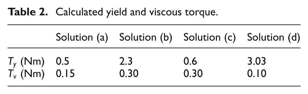
This analysis made it possible to develop the device schematically represented in Figure 1(d), which is composed of a cylindrical and a plane gap and has a torque capability which proved to be greater than that of the other analysed schemes (see Table 2). In particular, the advantages of this solution are given by the large size of the PM which can provide a high magnetic flux density in the cylindrical gap and in the large diameter of the cylindrical gap, which means a higher moment arm of the tangential forces and therefore a higher torque. The plane gap is not strongly magnetized but it also contributes to torque transmission. The viscous torque is lower than that obtained for the solutions (a), (b) and (c), due to the reduced total area of the facing surfaces.
Prototype design
From a magnetic point of view, the ferromagnetic and non-ferromagnetic materials distribution around the fluid was thoroughly investigated in order to confine the magnetic field within the regions of interest, whilst trying to maximize the mechanical torque (Rizzo et al., 2013). The MRF gap geometry, the PMs configuration as well as the materials selection were obtained at the end of an iterative procedure based on several FE analyses.
During this phase the 3D magnetostatic FE model shown in Figure 6 was employed, which, considering the problem symmetries, represents only one quarter of the whole structure. The FE model is made up of about
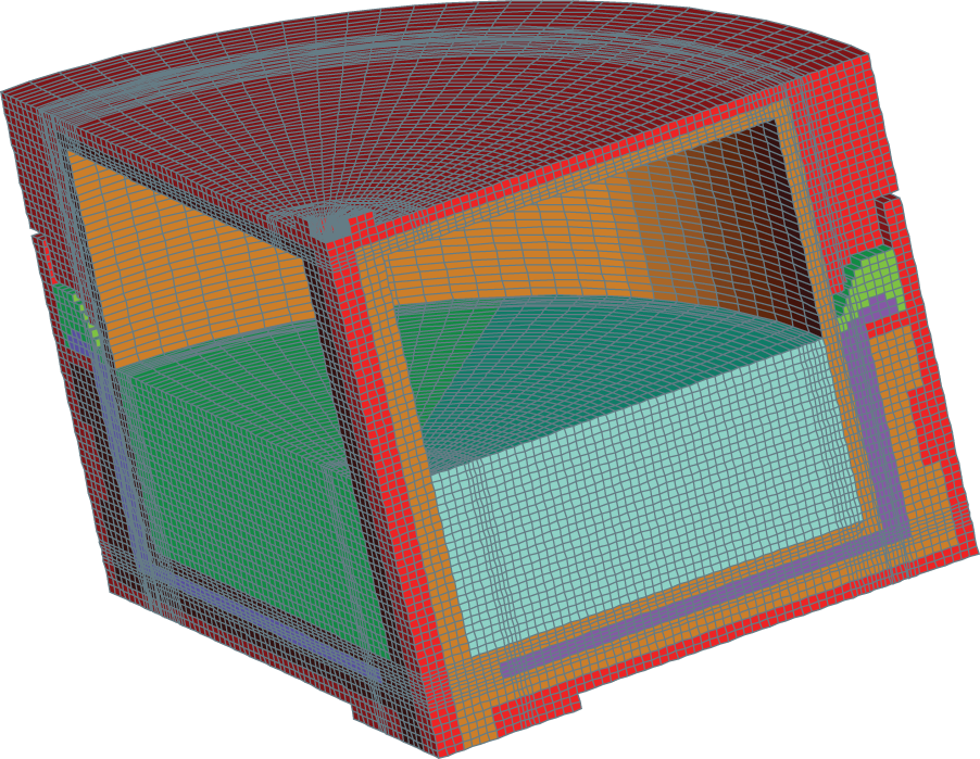
Hybrid geometry with a PM; 3D model.
The numerical simulations also made it possible to design the excitation system, which is based on a rare-earth NdFeB hollow cylinder. The number of poles and the magnetization type were chosen in order to maximize the torque within the given geometry, also taking into account the feasibility of the magnetic configuration with respect to the device dimensions and the reduction of the axial magnetic force. Figure 7 shows the radial and diametral magnetization for a four-pole magnet, while Figure 8 shows the magnetic flux density
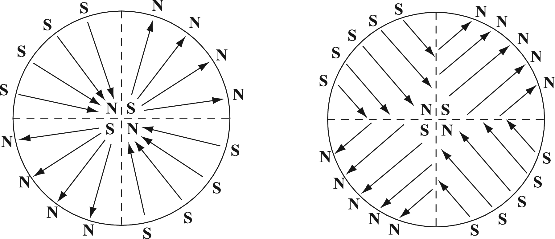
Radial (left) and diametral (right) magnetization for a four-pole PM system.
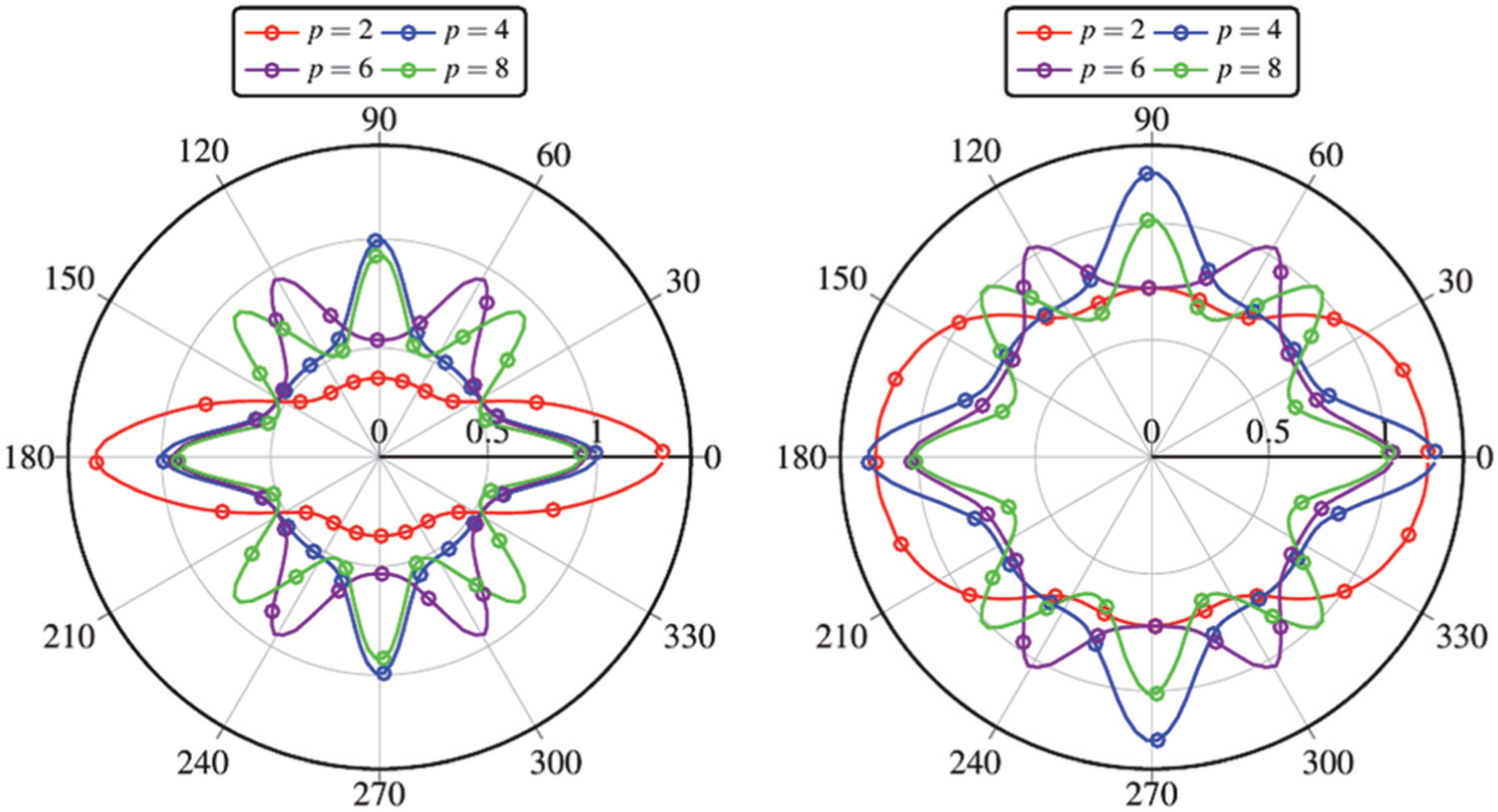
Magnetic flux density (Tesla) in the MRF as a function of the number of poles of the PM system: (left) radial magnetization; (right) diametral magnetization.
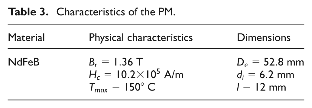
Characteristics of the PM.
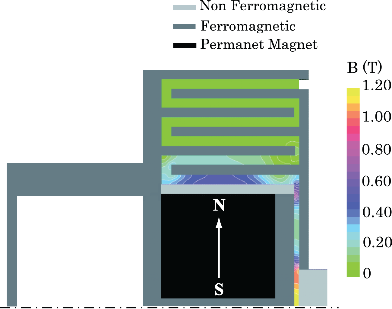
Finally, Figure 9 shows the map of the magnetic flux density B in the MRF in the disengaged (left) and engaged (right) configurations. As can be observed, when the PM is in the engaged state, the magnetic flux density is high enough to give a high level of transmissible torque. In contrast, the disengaged state is characterized by a very low magnetic flux density.
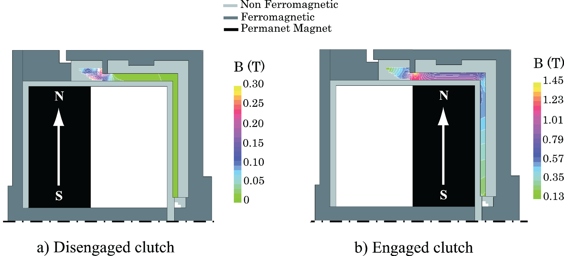
Magnetic field distribution in the disengaged and engaged configuration.
The developed prototype is depicted in Figures 10 and 11. The primary and secondary shafts are indicated as elements no. 1 and no. 2, respectively. The MRF film is represented in red. The gap is filled by removing the screws (no. 3) and is contained by the seals (no. 4 and no. 5). The magnetic field is generated by the magnets (no. 6) which can slide axially into a hollow cylindrical room. The room length is 26 mm, while the magnet thickness is 12 mm. Room and magnet dimensions were obtained by FE simulations aimed at reducing the magnetic field in the fluid in the disengaged configuration, maintaining the clutch as compact as possible. The two main parts that form the clutch are aligned by the bearings (no. 9); in particular, the primary shaft is centred with respect to the shell housing the magnets (no. 10), whereas, the secondary shaft is centred with respect to the crown, by three dowel pins; the Seeger ring (no. 11) fixes the relative axial position of the two halves and consequently the thickness of the plane gap. The external diameter and length of the prototype are 65 mm and 40 mm, respectively (see Figure 11), while the diameter of the input and output shaft is 15 mm. The MRF gap has an average diameter of the cylindrical part of 57 mm, while its thickness is 1.5 mm and 1 mm in the cylindrical and plane portion, respectively. The cylindrical gap is thicker to reduce the viscous torque in the disengaged condition, without loss in the magnetic field, thanks to the fluid and external steel ring saturation. In contrast, the plane gap was thinner to reduce the reluctance of the magnetic circuit.
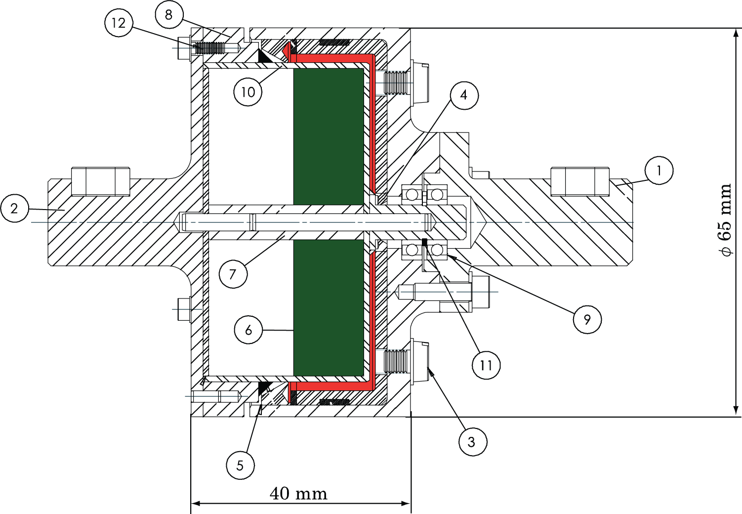
Prototype drawing.
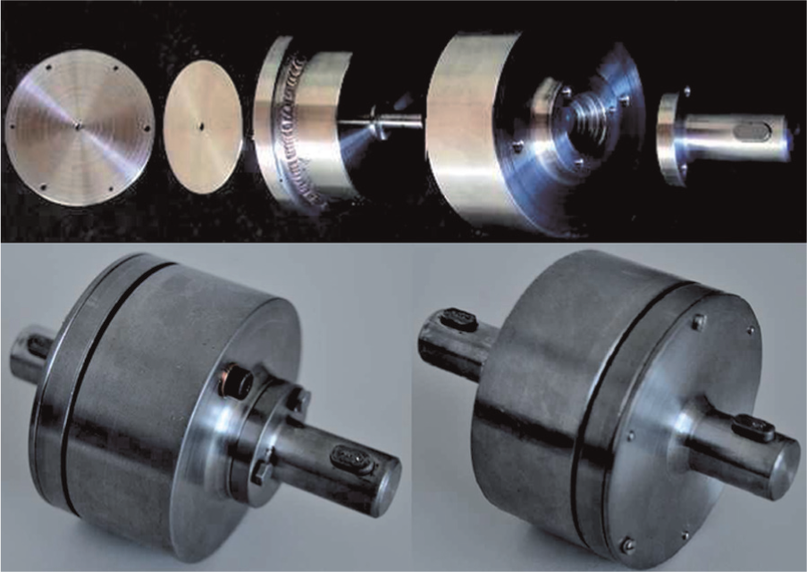
Pictures of the clutch prototype.
The operating principle of the prototype is represented schematically in Figure 12; when the magnets are moved towards the MRF gap (Figure 12(a)), the fluid is excited and the clutch is engaged; when the magnets are moved to the opposite side (Figure 12(b)) the fluid behaves like a Newtonian fluid and the clutch is disengaged. The first prototype was built without providing any actuation for the magnets axial motion as its main purpose was to measure the transmissible torque under various conditions (see Section 4.2) and to validate the models. The magnets actuation will instead be discussed in Section 3.
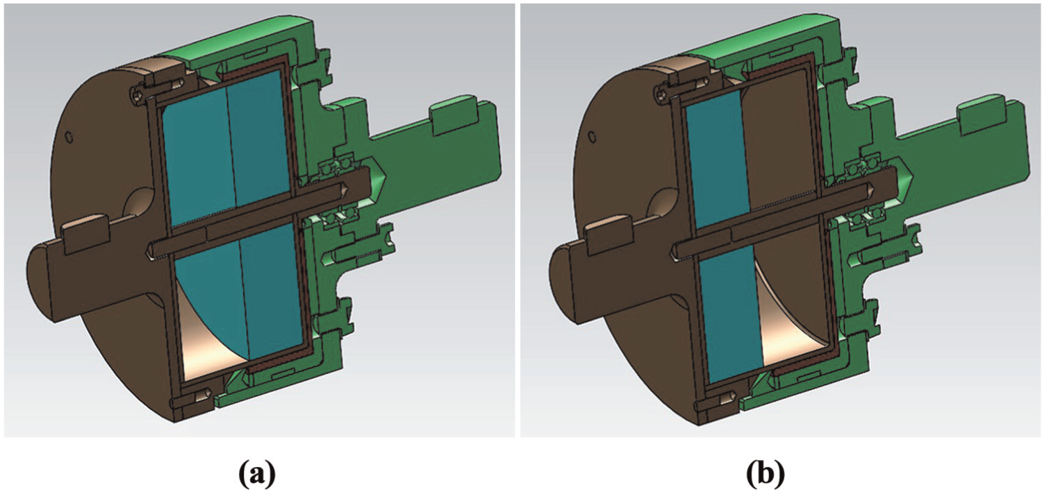
Clutch operating principle: (a) clutch in the engaged configuration; (b) clutch in the disengaged configuration.
Clutch actuation
In order to support the proposed clutch design, a feasibility analysis for the clutch actuation was carried out, even if the actuation system was not included in the first prototype. To ensure a fail-safe operation, the PM should be normally positioned so that the clutch is in the engaged configuration. Then, to disengage the clutch, a driving force must be supplied to overcome the magnetic force, the friction force and any other counteracting force in the axial direction.
Pneumatic actuation was recognized as the most suitable for the specific application, thanks to the availability of the vacuum pump (Bartalesi et al., 2013). To this aim, the chamber containing the PM is separated into two parts by means of a pneumatic seal attached to the PM, which can slide with low friction along the ON–OFF path. One of the chambers (the one on the right side) is connected to the atmospheric pressure
With reference to Figure 13 the following equation of motion holds for the magnet:
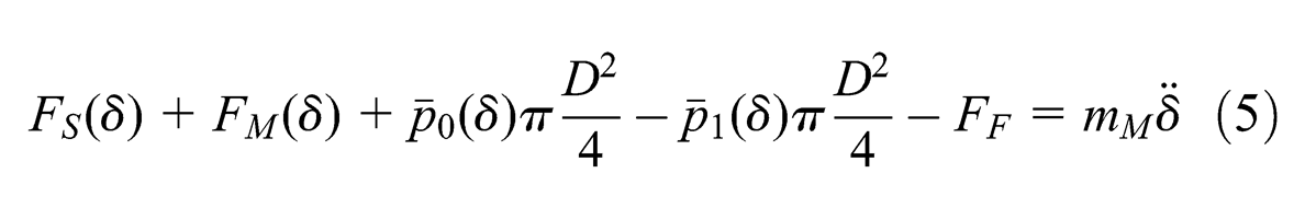
where
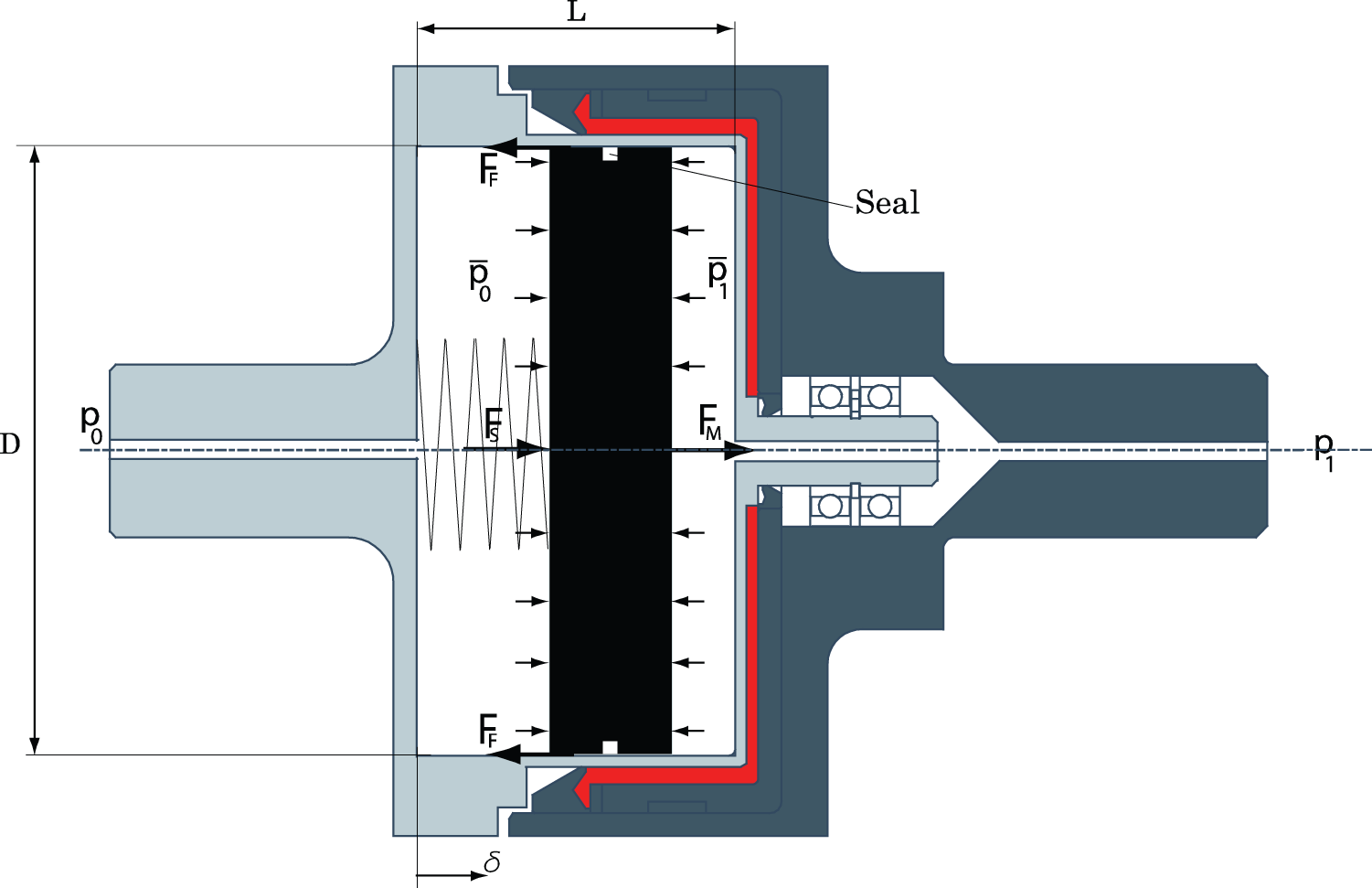
Magnet movement.
Equation (5) was numerically solved by considering a constant time step (
Let
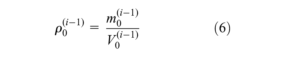
where the mass
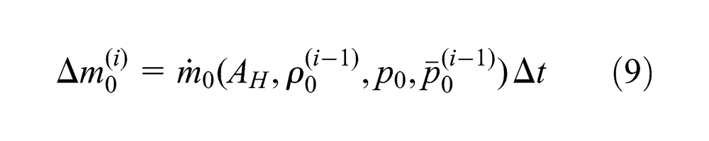
The mass of air at the next time step
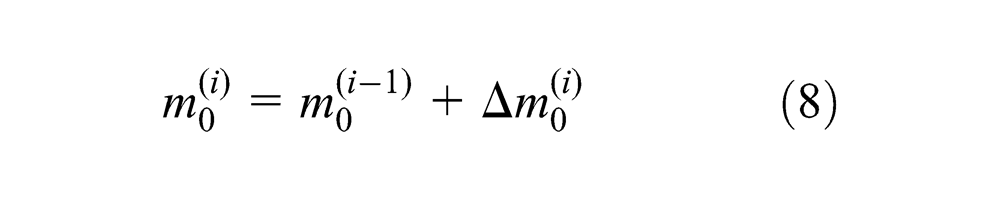
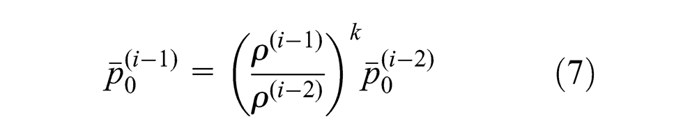
where
where
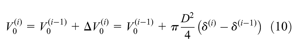
Then, the density and pressure in the left chamber are updated by Equations (6) and (7) and the process is iterated. The pressure
The spring stiffness and pre-load were then determined by some analyses in which the numerical procedure was employed. The final spring force is shown in Figure 14 together with the magnetic force. As a result, it can be observed how the magnetic force is always negative (directed leftward in Figure 13) and lower than the spring force. The magnet and spring resultant force is positive if no pressure force is applied, so in this configuration the steady equilibrium of the magnet is in the engaged condition. In contrast, if the difference of pressure is exerted, also the pneumatic steady force has to be considered and, in this condition, the magnet is in the steady equilibrium in the disengaged condition.
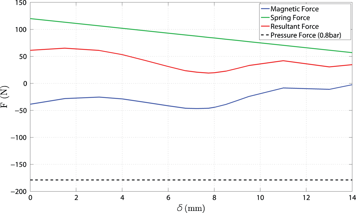
Forces acting on the magnet.
The transient from the disengaged to the engaged configuration was also analysed. For the transient analysis, an initial condition with pressure values of
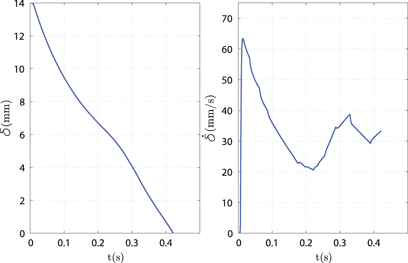
Magnet displacement and speed profiles: engagement phase.
As can be seen, the transient takes a few tenths of a second and the speed of the magnets approaching the end of the engaged chamber is about 0.03 m s−1. In conclusion, both results in terms of engagement time and impact velocity can be considered satisfactory even though an experimental validation, employing the real system, is necessary to obtain additional insights for an optimal definition of the actuation device.
Experimental characterization of the clutch prototype
Test bench and test procedure
In order to test the clutch prototype and to validate the analytical models, the test bench shown in Figure 16 was developed.
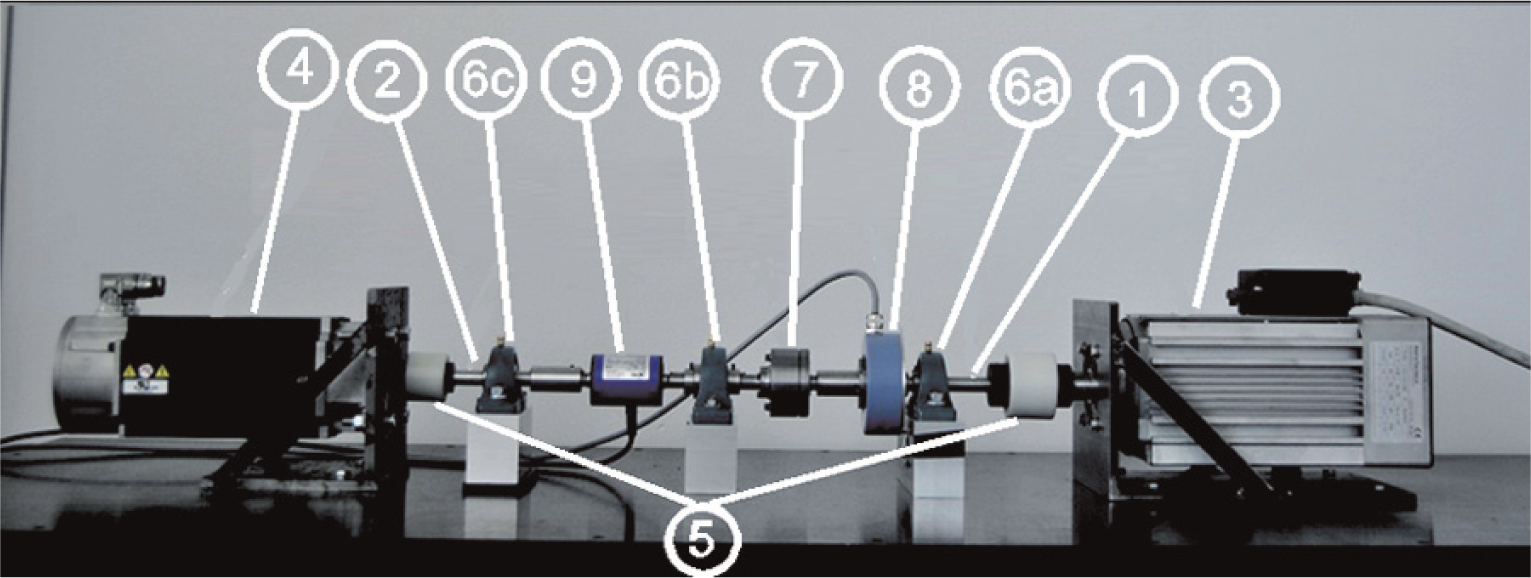
The test bench.
An asynchronous motor no. 3 and a brushless motor no. 4 are coupled to the shafts no. 1 and no. 2, respectively, through Sitex joints no. 5. The shafts are supported by ball bearings (Figure 16), two of which (i.e. (no. 6a) and (no. 6b)) are fixed to the bench by bolts and one (no. 6c) is fixed to the bench through a rubber pad in order to avoid overconstraining the system and to reduce vibrations at high rotating speeds. The torque transmitted by the clutch prototype no. 7 is measured by the torque meter no. 9, while the digital encoder no. 8, together with the encoder which is embedded in the brushless motor, gives the angular speed of the input and output shafts. The bench is controlled by a PC with a USB National Instrument DAQ board installed (
The desired rotating speed of the asynchronous motor is obtained by a proportional–integral–derivative (PID) controller which determines the frequency of the inverter on the basis of the error in the rotating speed (achieved thanks to the digital encoder). Several tests were carried out in order to tune the PID constants and it was verified that, under stationary conditions, the error between the actual and the desired rotating speed was below 1%. On the other side, the brushless motor has its own embedded controller and can operate either in torque or speed.
Two different kinds of tests were performed. The main test procedure, aimed at measuring the torque transmitted by the engaged clutch, consisted in fixing the rotating speed of the asynchronous motor (no. 3 in Figure 16) and applying an increasing braking torque to the brushless motor (no. 4 in Figure 16), until the speed of the secondary shaft went to zero. The clutch was also tested as a brake. In this case, the primary shaft was fixed to a support and the speed of the secondary shaft was increased. No effect of the rotating speed on the torque transmission was observed in the examined speed range.
Experimental results
The experimental results are given in Figure 17 in terms of transmitted torque versus relative speed between the input and output shafts. The plots that are shown in the figure refer to the engaged clutch, to the disengaged clutch and to the clutch after removing the magnet. Each experimental measurement was repeated three times and the repeatability of results was good, with the maximum deviation lower than 5%.
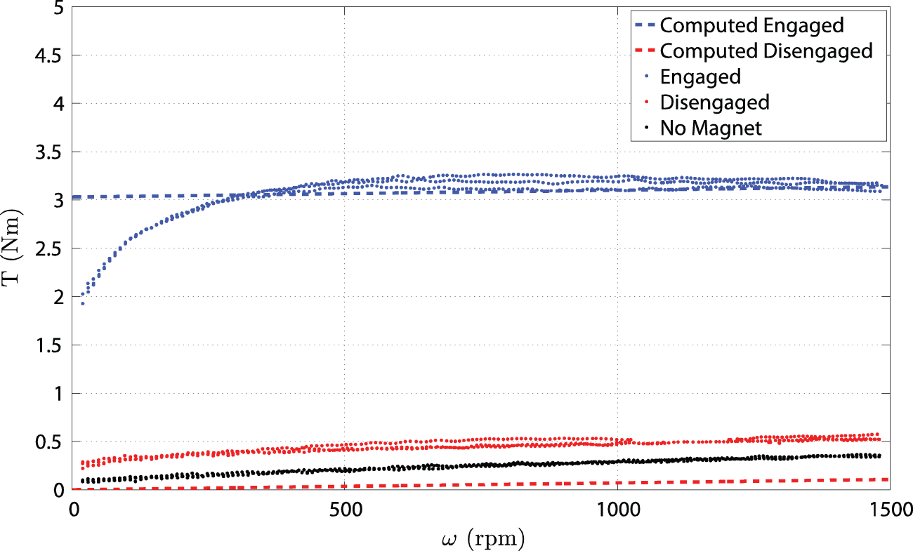
Transmitted torque.
The first curve confirms that the design requirements are met by the developed prototype. Indeed, the observed yield torque (about 2 Nm) is almost twice the torque which is required for normal operation (see Table 2) and in that case slip does not occur. Nonetheless, if occasionally and in short transients, the resistant torque overcomes the yield threshold, the clutch guarantees the transmission of up to the required maximum torque (see Table 2), in slipping conditions. Beyond that value the transmissible torque can still increase up to a saturation value of about 3.2 Nm.
On the other hand, clutch slip normally occurs in the disengaged configuration and the power dissipated is related to the disengaged torque. With reference to the disengaged curve, it can be concluded that, in the considered range, a maximum of about 62 W is dissipated at 1500 rpm (3000 rpm of the engine). The dissipated power could be further reduced to about half that value, by improving the MRF shielding from the magnetic field in the disengaged configuration. In fact, the comparison of the disengaged curve with that obtained with the magnets removed, where the torque is only due to viscosity and sealings friction, provides a difference of about 0.2 Nm that can be ascribed to the effect of non-perfect shielding of the MRF gap. In any case, on the basis of the previous considerations, it was concluded that the power dissipation is very low and therefore any temperature effect was neglected in this study, which was mainly aimed at demonstrating the feasibility of the proposed device. The temperature effect on the torque characteristic is discussed by Bucchi et al. (2013c).
The torque obtained by relationships (1)–(4) in the engaged and disengaged conditions are also given for comparison in Figure 17. It can be observed how the experimental yield torque is somewhat lower than that obtained by simulation; the observed difference was attributed to the adopted fluid model and to possible differences in the actual magnetic field, from that estimated by FE simulations. On the other hand, the torque computed in the disengaged condition accounts for the viscous contribution only and is lower than that obtained experimentally, due to friction in the sealings and bearings and to non-perfect shielding of the magnet.
Conclusions
The design of a MR clutch conceived for disengaging auxiliaries in an automotive engine has been presented and discussed. Different configurations have been considered before developing the final solution, by an iterative procedure, in which both mechanical design and magnetic field analyses were carried out. The main difficulties faced in the design were the simultaneous fulfilment of the size and torque requirements whilst maintaining low power losses. Particular care was therefore put into defining the gap geometry. The final design was the result of a synergic cooperation of different expertise in mechanical design and electromagnetism.
Thanks to the use of an MRF and a PM, a fail-safe operation, with negligible power consumption, reduced size and absence of axial loads, compared with conventional electromagnetic clutches, was obtained. In addition, the feasibility of an automatic actuation was also proved.
The clutch prototype has been tested on a purpose-built test rig and the first tests proved the satisfactory performance of the proposed clutch by complying with the design requirements. In particular, the yield torque was about twice the torque necessary to operate the vacuum pump during normal operation.
Footnotes
Funding
This work was funded by Pierburg Pump Technology Italy, S.p.A., within the framework of a project supported by Regione Toscana, P.O.R., C.R.e.O. and F.E.S.R. 2007–2013.