
Abstract
Recent innovations in microsystems materials and fabrication permit the creation of complex microactuation mechnisms with heterogeneous properties and behaviors. Meanwhile, emerging applications such as micro-robotics extend the environments in with microsystems may operate. This introduces substantial challenges for the design given the wide range of feasible devices. This paper describes a novel synthesis method based on structural topology optimization for the automated design of micro-robotic appendages realized by utilizing heterogeneous materials and embedded actuation. A typical mechanism designed by this approach, inspired by innovations in thin-film piezoelectric integration with other microstructures and materials, might include active smart actuators, elements formed from traditional semiconductor materials, and comparatively soft polymer flexures. We will introduce the framework for design optimization, and detailed procedure for problem definition, parameterization, and optimization. The focus of the synthesis is on realizing micro-robotic appendages that can achieve control of an end-effector in different directions (one and two). Original formulations of the optimization objective functions that lead to desired micro-robotic solutions are presented. Examples of different optimized designs are presented, with novel micro-robotic appendage solutions that can realize large in-plane displacement compared to prior devices, controllable actuation in largely-decoupled axes, and/or generation of unusual rotational displacement from initially planar geometries. Performance predicted by the design optimization algorithm is compared to simulated behavior through computational modeling. The presented synthesis method can be utilized by others to design micro-robotic solutions for different applications.
1. Introduction
Micro-robotics has become an interesting and increasingly relevant research topic for microsystem development (Adam et al., 2019; Chen et al., 2018; Das et al., 2012; Jang et al., 2019; Lee et al., 2020; Mavroidis, 2006; Palagi and Fischer, 2018; Siciliano and Khatib, 2016; Xu et al., 2019). Robots at millimeter-to-centimeter scales are often fabricated as micro-electromechanical systems (MEMS) (Adam et al., 2019; Chen et al., 2018; Ebefors et al., 1999; Hollar et al., 2005; Jang et al., 2019; Lee et al., 2020; Palagi and Fischer, 2018; Siciliano and Khatib, 2016; Xu et al., 2019), though some non-MEMS robots have achieved comparable scales by extending rapid prototyping capabilities (Chen et al., 2017; Rios et al., 2016; Soreni-Harari et al., 2020) and/or accepting small ranges of motion (Qu et al., 2017b). MEMS devices can be applied to integrate active transduction materials into complex microstructures to perform advanced electromechanical transduction at millimeter scales. MEMS-based robots also have potential advantages for close integration of power and electronics and low-cost batch fabrication.
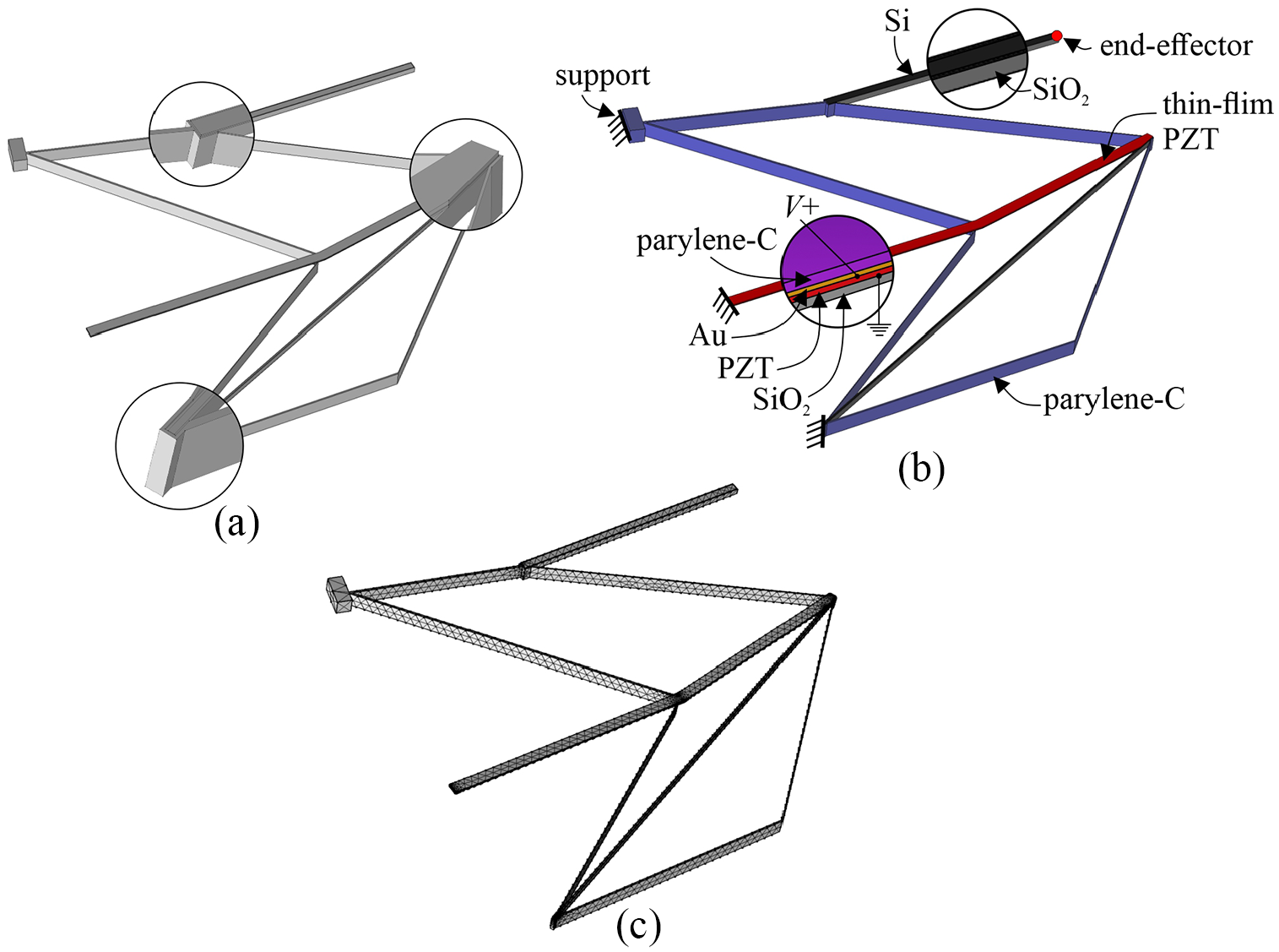
Among candidate transduction mechanisms for MEMS-based robots, including electrostatic (Contreras et al., 2017), electrothermal (Klotz et al., 2019), and shape-memory alloy (Takato et al., 2017) among others, piezoelectric materials offer benefits like high actuation speeds with small power consumption. Thin-film lead-zirconate-titanate (PZT), Figure 1, offers a promising solution for micro-robotic actuations tasks (Figure 2(a) and (b)), with advantages of having high work density per unit area and reasonable efficiency as a small capacitive load (Oldham et al., 2007; Pulskamp, 2012). Drawbacks include a complex fabrication process and small inherent stroke length. Cantilever bending (Rhee et al., 2012) or multi-segment mechanisms can increase displacements (Howell et al., 2013), but at considerable loss of load-bearing capacity. Our previous work (Choi et al., 2017; Qu et al., 2017a) has shown that a combination of comparatively soft (polymer) and rigid (silicon) beam-like elements can be integrated with thin-film PZT actuators to improve robustness and range-of-motion, in a selection of basic geometries (Figure 2(c) and (d)).
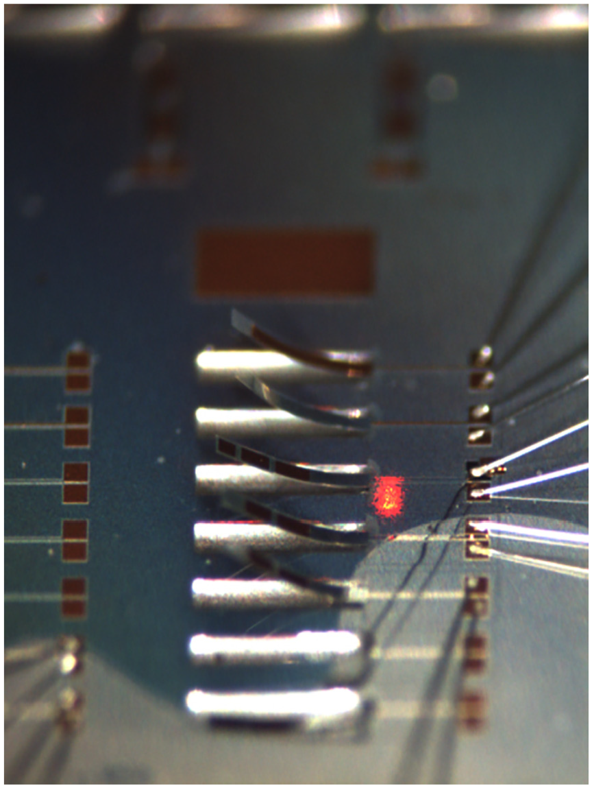
Thin-film lead-zirconate-titanate (PZT) actuators achieve large bending deformations in compact space (cantilever dimensions: 500 µm × 100 µm, actuated at 20 V).
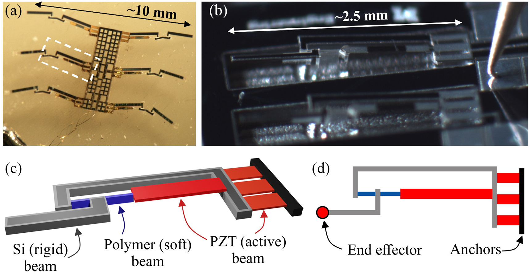
(a) A MEMS terrestrial micro-robot prototype with thin-film PZT as actuators (appendage is marked with a dashed square); (b) fabricated micro-robotic appendage sample comprised of thin-film PZT; (c) illustration of appendage design formed by combining thin-film PZT (active), Si (rigid) and polymer (soft) materials; and (d) corresponding beam-like model of appendage design used in synthesis (photo credits Dr. Jongsoo Choi).
Meanwhile, MEMS appendage design, especially among terrestrial micro-robot designs, has typically relied on designer experience, a trial-and-error approach, or seeking inspiration from biological organisms like insects (Figure 2(a)). Consequently, micro-robot properties and realized range of motion remain limited compared to, say, those of animals. A broader synthesis methodology for MEMS micro-robot appendages (Figures 2 and 3) is lacking. The goal of this paper is to develop a new design methodology for the realization of optimal micro-robotic appendages solutions given a wide range of candidate material sets.
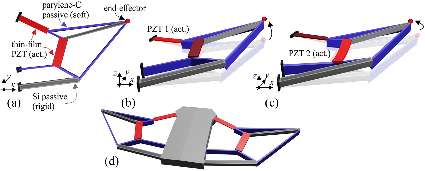
(a) Conceptual design of micro-robotic appendage comprised of thin-film PZT as active, parylene-C as passive (soft), and Si as passive (rigid) elements (plane view); (b) illustration of end-effector control in out-of-plane direction (PZT 1 active); (c) illustration of end-effector control in the in-plane direction (PZT 2 active); and (d) example of a MEMS terrestrial micro-robot design with two appendages.
Figure 3 shows a conceptual design of the micro-robot and its appendages. The proposed optimization can select from highly disparate micro-scale materials, active and passive (i.e. thin-film PZT, silicon, and parylene-C), and their geometries, to realize specific motions (Figure 3(b) and (c)) while satisfying other desired objectives. As a sample scenario, we will describe the design of appendages that can achieve a controllable range of motions across multiple axes when different thin-film PZT transducers are active (Figure 3(b) and (c)).
Structural topology optimization is adopted as a foundation for the proposed synthesis approach, derived mainly from structural engineering (Bendsoe and Sigmund, 2004) and compliant mechanism research (monolithic structures that realize motion via elastic deformation of multiple segments) (Howell et al., 2013). Topology optimization approaches have been considered before for the design of MEMS devices, including for micro-grippers (Grossard et al., 2009; Oh et al., 2008; Ruiz and Sigmund, 2018; Sardan et al., 2008), displacement inverters (De Leon et al., 2020), displacement/force amplification mechanisms (Huang and Lan, 2006; Pedersen et al., 2001), bistable micro switches (Tolou et al., 2011; Wilcox and Howell, 2005), individual PZT patches (Hu et al., 2018; Wang et al., 2006), and others (Bendsoe and Sigmund, 2004; Howell et al., 2013). Mostly these structures are comprised of only passive structural elements, and usually a single material. Actuators are added only after the MEMS design structure is obtained. In other words, the active elements are not included in the optimization process, but rather excluded and their placement (type, dimensions, orientation, location, characteristics) is left to designer choice. Synthesis of MEMS devices completely comprised of only PZT material has been realized in (Grossard et al., 2009), but this also excludes other material options.
Outside MEMS, topology optimization is extensively applied for the design of compliant mechanisms (Bendsoe and Sigmund, 2004; Howell et al., 2013; Milojević and Pavlovic, 2013; Parsons and Canfield, 2002; Saxena and Ananthasuresh, 2000; Zhu et al., 2020). Synthesis of compliant mechanism considering multiple materials is done in (Saxena, 2005), but not including optimal placement of actuators (active elements). In (Milojević and Pavlović, 2016) a method for simultaneous optimization of actuator placement and compliant structure topology is introduced (for shape morphing structure applications), but not considering the physical attributes of a specific type of actuator that is an inherent part of the system, and the problem of using multiple materials is not addressed. Other works include continuum-based topology optimization methods (Chu et al., 2018; Zhu et al., 2020), which are not applicable for the design of beam-like micro-robot appendages.
In general, previous optimization schemes cannot address the class of complex MEMS devices considered here. There is not an integrated method for consideration of multiple, highly variable materials in advanced MEMS devices, simultaneous optimization of active and passive elements, and dimensions of individual elements in one design approach, nor has this been considered within integrated design of an overall system, for example, with requirements on stroke and payload requirements. Thus, novel objective functions must be formulated. Further, all the approaches consider synthesis problems only in 2D while for micro-robotic appendages spatial 3D optimization is required. In the next sections, the synthesis methodology will be explained in detail, beginning with problem setup, then the optimization procedure, and followed by sample results on a selection of objectives and compared to full computational modeling.
2. Design methodology for MEMS micro-robotic appendages
This section describes the design methodology for the realization of MEMS micro-robot appendages accounting for both active and multi-material passive elements. We emphasize that when discussing micro-robotic appendages in this paper, active piezoelectric elements represent an inherent part of the appendage structure in combination with passive rigid and soft/compliant elements (Figure 3(a)). Here thin-film PZT plays a role as both structural elements (when not activated) and active elements (when activated). Thus, in the topology optimization, the placement (type, dimensions, orientation, location, characteristics) of both active and passive (soft/rigid) elements will be simultaneously optimized, considering that passive elements represent also multiple materials. Moreover, the placement of active elements (thin-film PZT) affects how the rest of the passive structure is formed, and vice versa. This substantially raises the level of complexity in the synthesis method compared to past design optimizations (Bendsoe and Sigmund, 2004; Chu et al., 2018; De Leon et al., 2020; Howell et al., 2013; Huang and Lan, 2006; Oh et al., 2008; Pedersen et al., 2001; Sardan et al., 2008; Saxena and Ananthasuresh, 2000; Zhu et al., 2020).
The classical topology optimization approach is illustrated on the example of MEMS-based motion amplification compliant mechanism synthesis (Figure 4). In the first stage that is, topology optimization, the designer only needs to set an initial problem (Figure 4(a)). This includes setting the design domain or space in which the mechanism should fit, input displacement/forces, material characteristics, supports, desired objectives, and other constraints (Figure 4(a)). Then through the optimization process, optimal material distributions or topology of the mechanism structure that can realize the given tasks are automatically obtained (Figure 4(b)). Additionally, a dimensional synthesis step can be used, where dimensions (width, height) of individual mechanism segments are optimized (Figure 4(c)). Further, shape optimization can be applied, where the overall shape of the mechanism structure is optimized (Figure 4(d)), or sometimes also the shape of the individual segments (Xu and Ananthasuresh, 2003). It is important to mention that not all three steps need to be used. In most cases for the design of MEMS structures, only topology optimization has been applied (Huang and Lan, 2006), as it represents a more “creative” part of the design process.
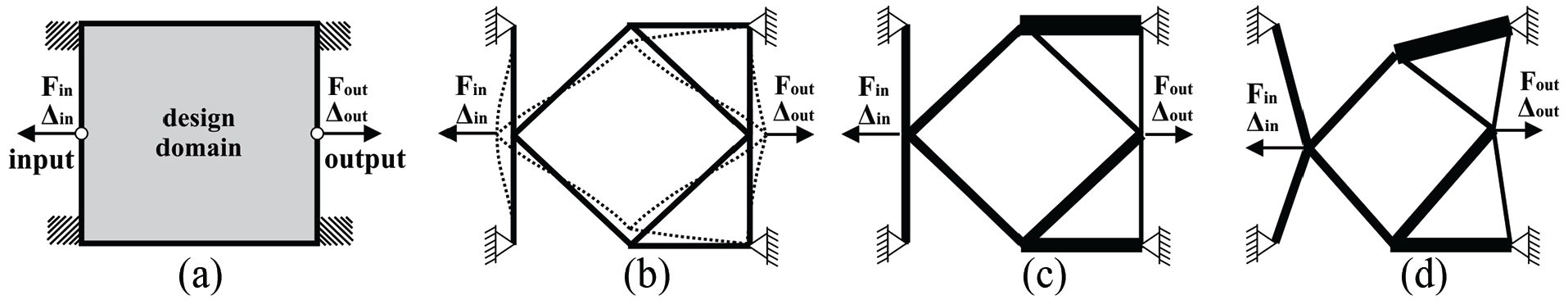
Structural optimization synthesis of MEMS motion amplification compliant mechanism (example): (a) the initial problem setup, (b) topology optimized solution, (c) dimensional synthesis, and (d) shape optimization.
Micro robotic appendages presented in this paper (Figure 3), resemble compliant mechanisms, or more broadly they resemble compliant systems: compliant mechanisms that also include actuators and sensors as a part of their overall structure (Milojević and Pavlović, 2016). In micro-robotic appendages, active elements represent actuators, where passive elements resemble elastic structures that realize the transfer of motion and forces to the end-effector.
From a synthesis perspective, a terrestrial micro-robotic appendage structure based on thin-film piezoelectric materials is comprised of beam-like:
Active, thin-film PZT elements (actuators), with four main layers: from the top, polymer encapsulation (parylene-C); structural metal (Au or Al), thin-film piezoelectric (PZT), base layer (SiO2) (Figure 5(a)); very thin top and bottom electrodes (Pt) transmit electrical inputs, with thin-film PZT contracting and bending when voltage is applied (Figure 5(a)),
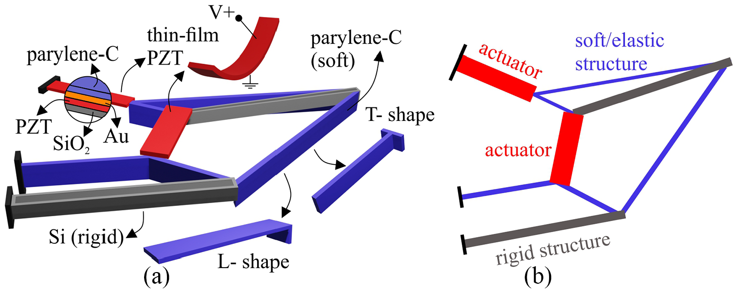
Micro-robotic appendage components (a) and corresponding beam-like model (b) used in the synthesis process.
Passive and rigid silicon-Si elements, formed when substrate silicon is retained,
Passive and comparatively soft parylene-C elements (Figure 5(a)); formed from combined surface deposition and trench refill, forming beams with either T- or inverted L-shaped cross-sections from the refilled and surface portions of the polymer film (Figure 5(a)).
These elements correspond to elements that have previously been co-fabricated with thin-film PZT (Choi et al., 2017). Conceptually, rigid Si elements are anticipated to perform substantial weight-bearing with parylene-C compliant elements at critical locations expected to amplify small piezoelectric input strokes, without exposing piezoelectric elements to excessive force from robot weight-bearing. However, the use of topology optimization permits design solutions beyond those conceived by individual designers. Figure 5(a) shows a solid model of a micro-robotic appendage design, as it might appear fabricated, and Figure 5(b) shows its beam equivalent. Considering the real physical connections between different material sets and how they are realized in produced form in the optimization framework represents a challenging task. The micro-robotic appendages are modeled in a beam-like form, where the connection between elements is simplified (point connections) as an advantage of the proposed synthesis method.
The synthesis goal we will describe here is to obtain the optimal design of micro-robotic appendages, comprised of the above elements, that can realize controllable motion (displacement) of an end-effector, in multiple directions (in-plane and/or out-of-plane), when different thin-film PZT actuators are activated (Figure 3(b) and (c)). This is motivated by the longer-term aim of realizing micro-robots that can use their appendages’ variable motion capabilities for terrestrial locomotion over varying terrains (Figure 3(d)).
The proposed structural synthesis combines the following phases in one optimization approach:
Topology optimization that is, finding the optimal distribution of thin-film PZT, soft parylene-C (including multiple candidate cross-sections, labeled “T” or “L”), and rigid Si elements
Dimensions of individual elements (width, length), and
The shape of the overall micro-robotic appendage, all at once.
Additionally, to realize micro-robotic appendages design that can achieve motions in different directions, spatial-3D structural optimization must be realized. Such a highly complicated synthesis problem is not solved before for the design of MEMS devices or in the field of structural optimization.
In our previous paper (Milojević et al., 2019), an initial topology optimization approach for the design of micro-robotic appendage was introduced. In Milojević and Oldham (2020) ) we introduced the optimization of appendages considering performance properties like transport ability (payload requirements), projected walking speed, and power consumption, but not for realizing end-effector control. In both prior prelinary works (Milojević et al., 2019; Milojević and Oldham, 2020) the method was not described in detail and only a basic investigation was done presenting one synthesis case and a very limited number of appendages design solutions. Moreover, finite element method (FEM) simulations and verification of the obtained results were not realized in (Milojević et al., 2019). The obtained results are compared only with the one standalone PZT cantilever range of motions, and further meaningful conclusions could not be made with respect to more complex geometries. This paper presents the synthesis method in more depth, explaining all aspects and steps of the proposed synthesis optimization approach. Specific elaborations include different and multiple design cases (appendage design for end-effector control in one direction and control in two directions with various cases of axis direction control), associated novel optimization objective functions, expanded results, verification of results via FEM simulations, and comparison with prior devices performance under more general criteria.
2.1. Synthesis methodology overview
The proposed synthesis methodology includes three steps: problem setup (Figure 6(a)), parameterization (Figure 6(b) and (c)), and optimization (Figure 6(d) and (e)). First, problem specifications are set (Figure 6(a)). This includes defining: design domain shape and dimensions, location of the supports, input voltage for the thin-film PZT, location of the output (end-effector), desired directions of motion that is, control of the end-effector point, external loads, material characteristics of elements that form the appendage (e.g. Young’s modulus), and other constraints if desired. The solution to the specified problem (Figure 6(a)) represents an optimal design given the specific problem definition (Figure 6(i)).
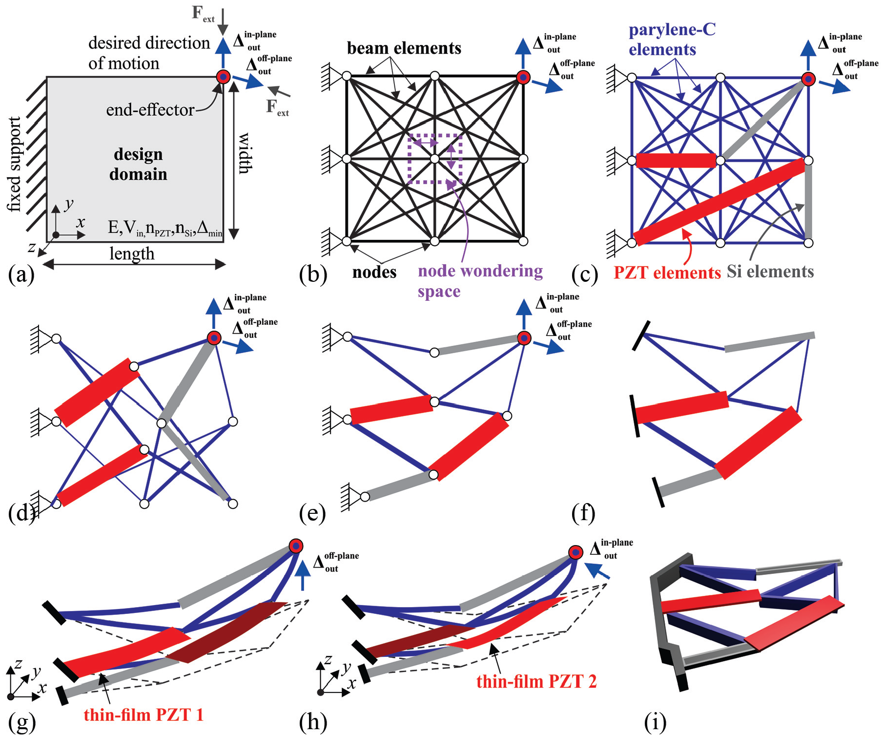
Steps in the synthesis methodology for the micro-robotic appendages: (a) problem specifications; (b) parameterization of the design domain; (c) selection between different active (thin-film PZT), passive soft (parylene-C), and passive rigid (Si) elements; (d) optimization process; (e) topology optimized solution of the micro-robotic appendage; (f) 3D solid model; (g) deformed position when thin-film PZT 1 is active (end-effector motion in out-of-plane), verified via FEM analysis; (h) deformed position when thin-film PZT 2 is active (end-effector motion in in-plane), verified via FEM analysis; and (i) appendage prototype.
Next, the design domain is parameterized (Figure 6(b) and (c)). Due to the discrete beam-like design of micro-robotic appendages, common with many MEMS devices, the grounded structure approach (GSA) is adopted for parameterization (Milojević and Pavlovic, 2013; Parsons and Canfield, 2002; Saxena and Ananthasuresh, 2000). The design domain is divided into a number of nodes and a network of beam elements connecting these nodes (Figure 6(b)). Alternate methods for discretization include the block-based method (Grossard et al., 2009), but such a method permits only limited exploration of available design space. Further, continuum discretization methods are possible (De Leon et al., 2020; Oh et al., 2008; Pedersen et al., 2001; Zhu et al., 2020), but they are not applicable here due to the need for a finite geometrical definition of material elements in layout for fabrication (Figure 5). Moreover, those methods are limited only to the synthesis of passive material structures (De Leon et al., 2020; Pedersen et al., 2001; Zhu et al., 2020) or combined materials where active element location is present and only orientation is variable (Carbonari et al., 2005; Wang et al., 2014). The net of elements shown in Figure 6(c) represents the initial problem solution, among which the optimal micro-robotic appendage design is searched. In our process, all the initial elements in the net represent soft parylene-C elements, while during optimization, simultaneously, some elements are chosen to become active PZT-elements and some to become passive rigid Si-elements. Additionally, any element may be removed/returned from/to the structure. Thus, the design variables are a variable that turns on/off elements, a variable that selects a soft parylene-C geometry (T or L cross-section), a variable that defines the choice of active thin-film PZT elements, a variable that defines the choice of rigid Si elements, and variables for dimensions (width) of each element. Further, the shape of the overall appendage is optimized by allowing individual nodes of a structure to wander within the predefined regions (Figure 6(b)); changing the lengths and positions (to some extend) of individual active and passive elements. Thus, for each node two variables exist. All the variables are optimized in one synthesis process.
When the parameterization is done, a method must be applied to find the optimal solution for the specified criteria (Figure 6(d)). Due to the very large design space, optimization is implemented as a search method. The discrete nature of the problem (elements are on/off from the design domain, variables have discrete values) motivates us to apply a discrete optimization method, of which an evolutionary Genetic Algorithm (GA) is applied here (Haupt and Haupt, 2004). GA’s are very suitable when searching a design space with a broad range of design variables and reaching a global optimum for a given problem. Moreover, GA’s are extensively used in different structural optimization and compliant mechanism problems (Milojević and Pavlovic, 2013, 2016; Parsons and Canfield, 2002; Prasad and Diaz, 2006) and have proven to be a very efficient optimization method.
When the optimization converges and finds a solution, some elements will have been removed from the design domain, some will have become active PZT elements, and some will have become rigid Si elements. Further, the dimensions (width) of the elements together with the position of the nodes will be optimized. The elements that remain present form the optimal design of the micro-robotic appendage (Figure 6(e)).
To move toward physical realization, from the obtained solution a solid 3D model is designed, considering fabrication constraints (Figure 6(f)). The finite element method (FEM) characterization is done to verify the behavior of the realized appendage design (Figure 6(g) and 6(h)). This structure can also be used to help define the photolithography mask for MEMS fabrication (Figure 6(i)).
2.2. Problem definition
As a first step in the synthesis process, the problem definition is set, including desired inputs and outputs. For the design of micro-robotic appendages, several synthesis cases are investigated, and different problem setups need to be defined (Figures 7 and 8).
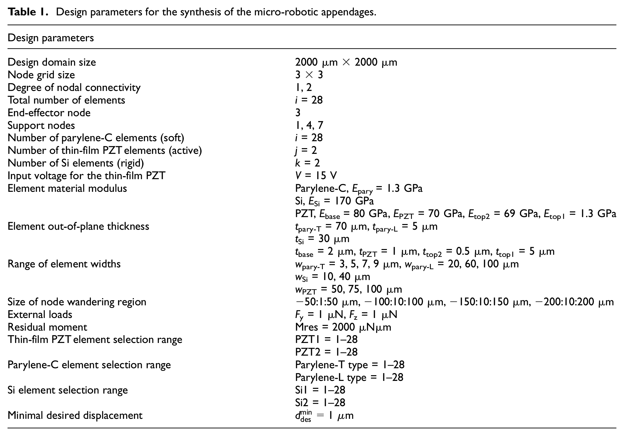
First, the rectilinear design domain is defined (Figures 7 and 8). Here, the fixed support is applied arbitrarily as the left edge of the design domain, representing the connection to a robot body. The right-top edge point is selected as an end-effector location. External loads that act on the micro-robotic appendage are defined at the same location as the end-effector (in in-plane and out-of-plane direction). This is done to represent the effect of a payload on the appendage design. A force value of 1 μN is used which for the synthesis cases presented in this work is sufficient to yield realistic robotic appendages. As an input, the appropriate value of voltage is used for the thin-film PZT. Material properties for all the elements (parylene-C, Si, and PZT) are defined, together with the desired range of element widths (mainly dictated by fabrication constraints) and other dimensions. The number, though not other attributes, of desired thin-film PZT and Si elements used in the micro-robot appendage design, are predefined, reflecting finite electrical connections and paths available in physical prototypes. The specific parameters that are used for the synthesis of the micro-robotic appendage are given in Table 1.
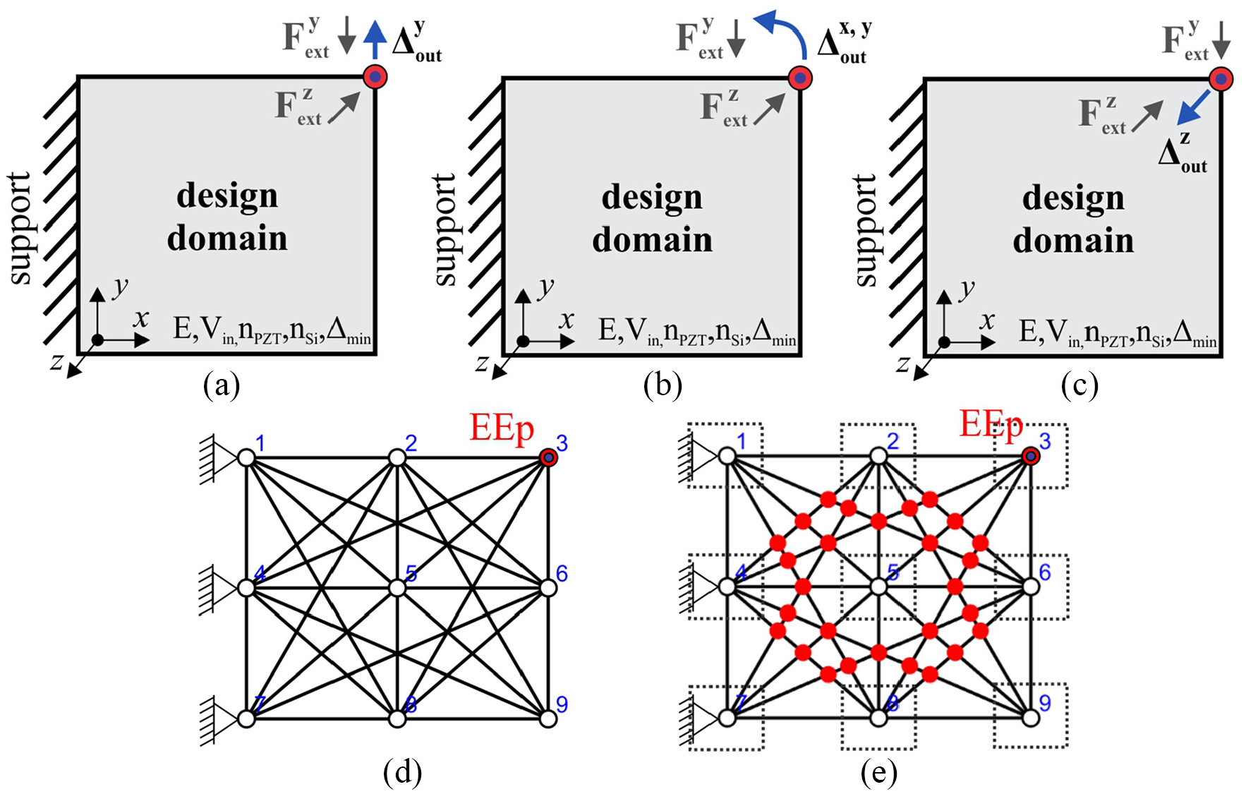
Synthesis of the micro-robotic appendage for the end-effector control in one direction: (a) problem definition for control in the Y direction (in-plane); (b) control in the X + Y direction (in-plane); (c) control in the Z direction (out-of-plane); (d) ground structure used in the synthesis with end-effector point (EEp) marked (the same ground structure is used in all three cases); and (e) ground structure with 44 detected intersections (marked with red dots) and node wandering ranged (marked with dash line).
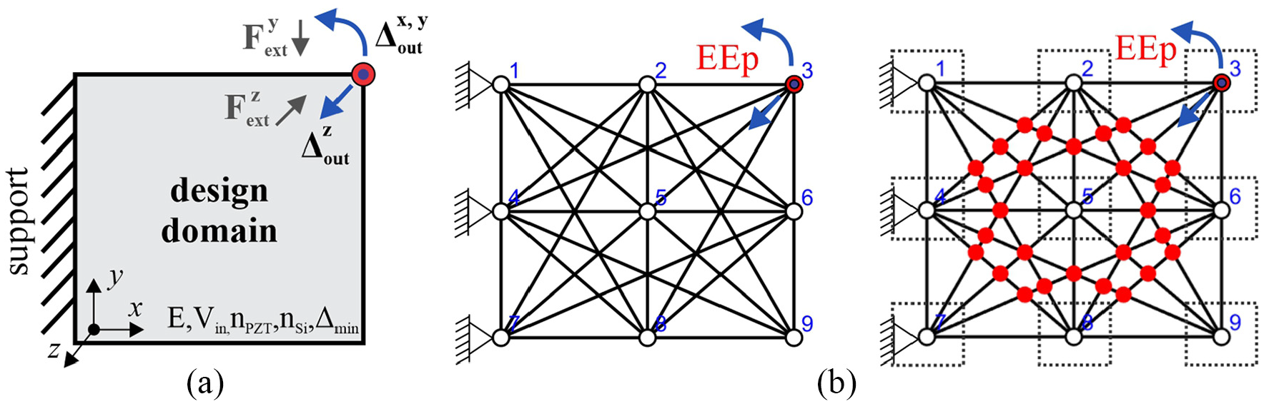
Synthesis of the micro-robotic appendage for the end-effector control in multiple directions: (a) problem definition for the control in two directions, X + Y (in-plane) and Z (out-of-plane); and (b) ground structure used in the synthesis (left) and detected 44 intersections-red dots (right) and node wandering region.
Design parameters for the synthesis of the micro-robotic appendages.
As examples of design objectives that can be addressed by these methods, we will focus on the control of end-effector motion, with two different cases that are investigated (Figures 7 and 8). These are optimized control of motion in:
one direction (Y—in-plane, X and Y—in-plane, or Z—out-of-plane), Figure 7(a) to (c),
two directions (X and Y—in-plane, and Z—out-of-plane), Figure 8.
In all cases, the rest of the problem specification parameters are the same (Table 1).
2.3. Parameterization
Using the GSA approach, the rectilinear design domain (Figures 7(a) to (c) and 8(a)) is divided into an nw × nh grid of nodes, connected by a net of beam elements (Figures 7(d) and 8(b)). For the ground structure formation, spatial beam elements with 6 degrees of freedom at each node are used. The following design variables are defined:
The actual number of overall variable count depends on the initial ground structure density and number of active and passive elements used (e.g. for one synthesis case the number of variables can be more than 100, Figure 7). This makes the design space large and thus the optimization problem complex to solve.
The range of variable values, together with other design parameters for parameterization of the design domain, are given in Table 1.
2.3.1. Definition of the ground structure
Initially, in the ground structure, all the nodes are interconnected (Figure 9(a)), with one element placed between every two nodes. Such a ground structure is known as a fully connected ground structure and often can lead to design solutions that contain overlaying elements (one on top of the other, where elements are in two parallel planes) Figure 9(a). Design solutions with overlaying elements are difficult to produce in MEMS fabrication. To avoid this, a filter (computer-coded algorithm) is developed that searches for and eliminates overlaying elements before further optimization.
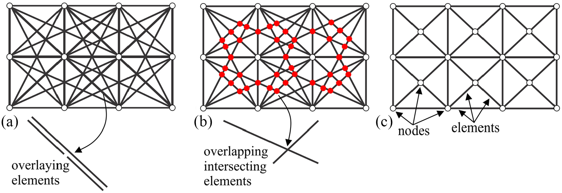
Illustration of: (a) fully connected ground structure with overlaying elements, (b) reduced ground structure with overlapping intersecting elements, and (c) simplified ground structure.
To realize better control over how the design domain is discretized, a degree of nodal connectivity is introduced as a constraint. A limit (number of nodal connectivity, nnode) is set, which defines how many fields one element can cross that is, with how many neighboring nodes can one element be interconnected (Table 1). This also simplifies the initial ground structure (which can speed up the optimization process significantly) but without losing the integrity of the available design space.
The initial reduced ground structure is still complex and can lead to solutions that contain overlapping (intersecting) elements without shared nodes after optimization (Figure 9(b)) (Milojević and Pavlovic, 2013), again very hard to fabricate in a MEMS device. In topology optimization, this problem is usually solved by using a simplified ground structure (Figure 9(c)), where one node is connected to only neighboring nodes (in one field) (Parsons and Canfield, 2002; Saxena, 2005; Saxena and Ananthasuresh, 2000). But such a simplified ground structure (Figure 9(c)) cannot effectively represent the design domain, as many potentially good design solutions are lost at the beginning. In the proposed synthesis, the reduced ground structure is adopted (Figure 9(b)) to capture many more potential design solutions. Then, one solution for avoiding overlapping elements would be to define nodes at the location of crossing elements. But such a ground structure leads to solutions with many intersections and increased stiffness of the overall design (Milojević and Pavlovic, 2013; Prasad and Diaz, 2006). This is not always desirable, as most of the thin-film PZT actuation would be spent to deform the rest of the structure, and a very small portion of the input displacement/force would be transferred to the output. Further, this could also lead to elements with very small lengths, which can also be difficult to fabricate. Instead, to avoid overlapping intersecting elements, a filter is integrated into the optimization code. During the optimization process, the filter searches for and identifies interesting points between all the elements (soft, rigid, and active). Then, the total number of interesting points is calculated, for every potential solution. As a goal is to avoid overlapping elements, the total number of interesting points (nintsec) should be minimized during optimization. This number (nintsec) is then used as a constraint, rather than as an objective function goal (see section 2.4.2).
The grid density, degree of nodal connective, as well as the total number of soft, rigid, and active elements, that are used for the design of micro-robotic appendages are given in Table 1.
2.3.2. Active, thin-film PZT, element model
When voltage is applied to a thin-film piezoelectric (PZT) unimorph, it both contracts and bends (the latter due to fabrication on a passive base layer) (Figure 10(a)). Prominent characteristics of a thin-film PZT actuator can be described by its force-displacement curve. In most topology optimization models, the force—stroke (or displacement) relation is treated as linear, with force modeled separately from the mechanism structure. But the thin-film PZT elements in this problem are embedded in the appendage structure, while output force/moment decreases when active element deformation increases. Further, in the micro-robotic appendages, thin-film PZT can play a role as both an active and passive structural element when different PZT elements are actuated. These characteristics of the thin-film PZT need to be captured in the appendage optimization process.
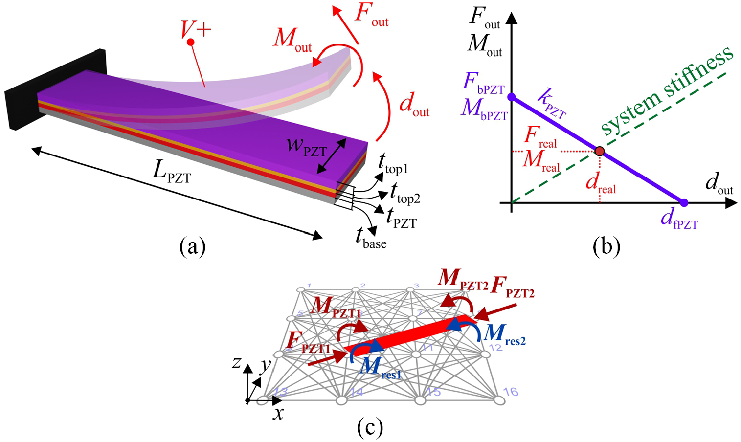
(a) Model of the thin-film PZT; (b) actuator characteristics diagram used in the synthesis; and (c) thin-film PZT model implemented in the synthesis.
Figure 10 shows thin-film PZT with a corresponding equivalent beam model. To represent the real actuator operation, in the model (and optimization) voltage is applied as an input. For a thin-film PZT beam, the strain is generated primarily along the long axis, leading also to out-of-plane bending due to the unimorph beam structure. The axial thin-film PZT output force will be a portion of the blocking force (FbPZT), the output moment will be a portion of the blocking moment (MbPZT), and realized displacement will be a portion of the free displacement (dfPZT). Here the overall stiffness kPZT of the thin-film PZT actuator is symbolically illustrated in Figure 10(b). The realized actuator force (Freal), moment (Mreal), and displacement (dreal) are determined by its interaction with the rest of the appendage structure.
In the optimization, the actuator model is implemented by applying axial forces (FPZT1, FPZT2) and out-of-plane moments (MPZT1, MPZT2) at both ends of the active beam elements (Figure 10(c)). The coupling between the applied input voltage and generated forces (FPZT) and moments (MPZT) is approximated by:
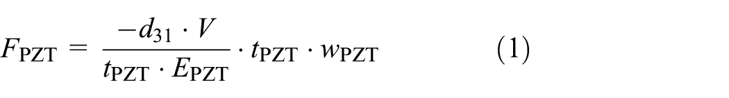

where d31 is the effective piezoelectric strain coefficient for the thin-film, V is the input voltage, tPZT is the thickness of the piezoelectric layer, wPZT is the width of the whole thin-film PZT, EPZT is Young’s modulus of the piezoelectric layer, and zPZT represents the distance between the midline of the PZT layer and the neutral axis of the multi-layer beam.
In addition to actuating forces and moments, the effects of residual stresses in the thin-film PZT are considered. During the deposition, layers in the PZT unimorph (SiO2 support layer, Pt electrodes, PZT, and top Au reinforcement layer) develop internal stresses due to thermal expansion coefficient mismatch and intermolecular forces at layer interfaces, among other mechanisms. The exact amplitude of residual stresses is sensitive to fabrication details but generally produces moderately tensile stress in upper layers, curling beams upwards relative to the substrate. Estimated effects are included in the model and optimization by applying corresponding residual moment at both ends of the thin-film PZT elements (Figure 10). Parameter values for the investigated synthesis cases are given in Table 1.
2.4. Optimization
Optimization is applied as a search method to find the optimal appendage within the large design space (Figures 7 and 8), given various criteria applied via the objective function and constraints. As different synthesis problems are investigated, corresponding objectives are defined:
(1) control of the end-effector in one direction (in-plane or out-of-plane); when all thin-film PZT elements are activated together the end-effector should move in only the desired direction,
(2) control of the end-effector in two directions (in-plane and out-of-plane); here two thin-film PZT’s are used, where each should realize end-effector displacement in only one direction.
When realizing end-effector control in multiple directions, activation of individual PZT elements affects the motion of the whole appendage structure, not only the end-effector. This could lead to realizing end-effector displacement in the same or similar manner although different PZT’s are activated. In other words, the given set of thin-film PZT’s could produce the same or similar output motions of the end-effector, not realizing desired control. Further, this means that the end-effector displacements in different directions are not decoupled but rather highly dependent. To obtain appendages solutions that can realize a large difference between end-effector motion in different directions, when separate PZT’s are activated, a controllability concept is introduced.
2.4.1. Controllability criteria
The controllability concept/term is borrowed from classical control theory but applied here as a static criterion. The controllability of a system is usually described as the ability for a given set of control inputs to transfer the system from its initial state to any final state, in a finite time interval. But for the synthesis of micro-robotic appendages here, controllability is defined as how well the given set of thin-film PZT’s can realize different output motions of the end-effector. In strict form, full controllability is achieved if each PZT, when activated, produces a pure displacement of the end-effector in only one, unique, direction.
For a general case with multiple active elements, this controllability is calculated by
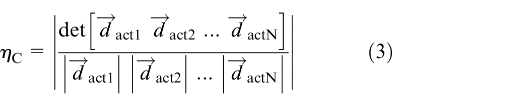
where
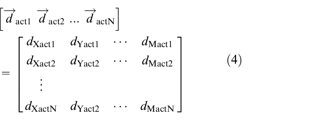
Here
To obtain a micro-robotic appendage design that can realize control in multiple decoupled directions, this controllability value must be high. Thus, controllably as measured above should be maximized in the optimization. In this synthesis, control of an end-effector in two directions is investigated during the second study to be presented, thus N is equal to 2; for end-effector control in one direction, the controllability concept is not necessary.
2.4.2. Objective functions for the micro-robotic appendage synthesis
An objective function must be defined to guide the optimization toward the desired goal. As several synthesis cases are investigated with a different goal, several examples of objective functions are described.
The objective function for the case of end-effector control in one direction is given in a form:
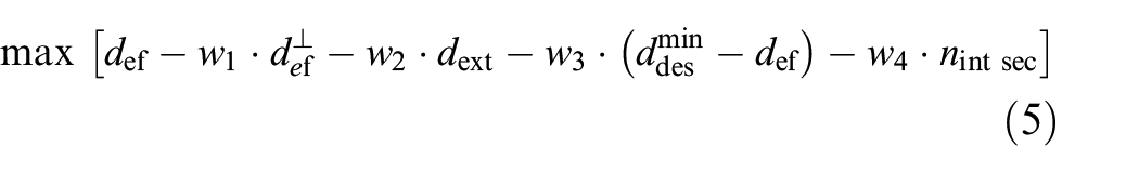
Here the output displacement of the end-effector in the desired direction of control (def) is primarily maximized, while displacement in the perpendicular direction (
Control in only in-plane on either a specified axis
Or in the general plane (Figure 7(a) and (b)) and
Control in the out-of-plane direction (Figure 7(c)).
In each case, all PZT’s are activated together.
For end-effector control in two directions, the objective function is:
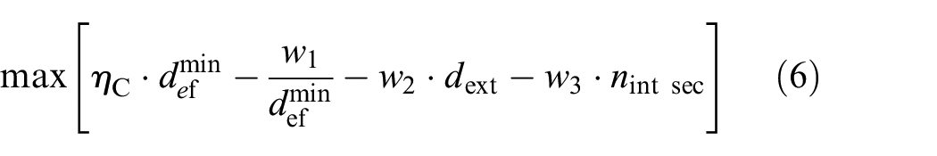
Here control is distinguished between in-plane (X+Y-direction) and out-of-plane (Z-direction), Figure 8(a), thus the controllability ηC term is maximized. Additionally, the output displacement of the end-effector (in-plane and out-of-plane) is maximized as well through
For all cases (equations (5) and (6)), the synthesis problem represents a multi-objective optimization problem, that is reduced to a single-objective optimization problem by using weighting constants (wc). For each of the above cases, different formulations of objective functions, concerning terms and their weights, were explored. This is done initially through a trial-and-error approach and based on the authors’ previous experience, with desirable outcomes being behaviors that are well differentiated from past work, such as large displacements with high out-of-plane stiffness, or novel end-effector motions. During optimization, the terms in the objective function (equations (5) and (6)) are calculated using linear FEA.
2.4.3. Optimization method
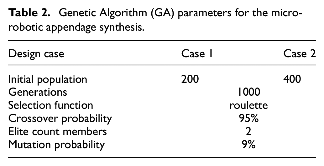
As an optimization method, a Genetic Algorithm (GA) is adopted (Darwish, 2018; Haupt and Haupt, 2004). GA’s are especially suitable for solving discrete nonlinear problems (like this optimization of micro-robotic appendages) and finding a global optimum. Chromosomes in the GA are comprised of genes, each representing a characteristic of the appendages (design variables). Reproduction of offspring and evaluation of fitness is repeated until the maximum number of generations is reached or improvement of fitness function halts over a certain period. The GA parameters used for synthesis of the micro-robotic appendages are given in Table 2. Separate GA’s are run for each investigated case (Figures 7 and 8).
Genetic Algorithm (GA) parameters for the micro-robotic appendage synthesis.
3. Results of micro-robotic appendage synthesis
Multiple GA optimizations are run for all the investigated cases (Figures 7 and 8), using a variety of weightings and initial settings for the objective functions. During optimization, soft parylene-C elements will be turned off/on from the initial topology set, some elements will become active thin-film PZT and some rigid Si elements, the dimensions of the individual elements will change together with positions and locations of the nodes, while the occurrence of intersecting elements will be avoided. The remaining parylene-C elements with selected thin-film PZT and rigid Si elements, as well as chosen node locations, will form the optimal micro-robotic appendages solution. The results of individual synthesis cases are presented and discussed below.
3.1. Micro-robotic appendage designs for end-effector control in one direction
A sampling of obtained optimal solutions for control of an end-effector in one direction is shown in Figures 11 to 13, as follows:
End-effector control in the Y direction only (in-plane)—Figure 11,
End-effector control in combined X and Y direction (in-plane); out-of-plane motion is constrained—Figure 12,
End-effector control in the Z direction only (out-of-plane)—Figure 13,
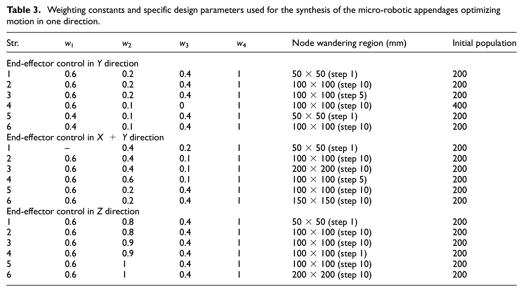
Solutions are realized under different initial parameters, nodal connectivity, range of node wandering space, and values for weighting constants (wc), to explore design trends. Tables 1 and 3 contain the parameters used for results shown in Figures 11 to 13.
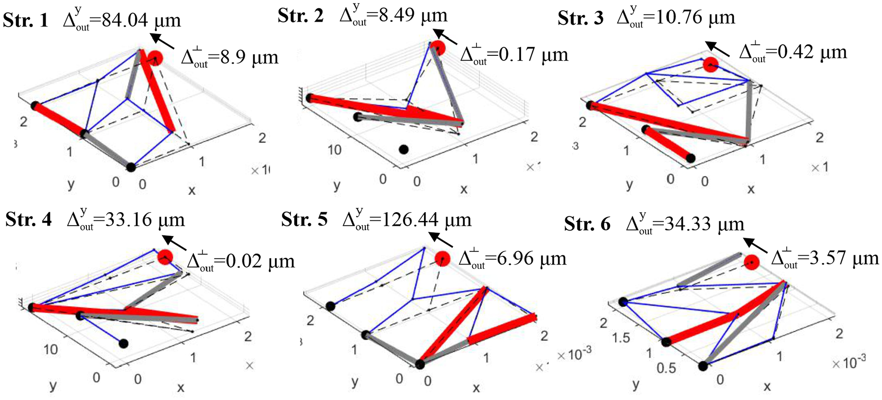
Optimal solutions of the micro-robotic appendage synthesis for the end-effector control in Y axis in-plane, shown in active-deformed position (initial position is shown with dash lines); deformations are scaled for clarity. Candidate elements: parylene-C (soft), Si (rigid) and thin-film PZT (active). Elements that are on both ends connected to the fix nodes do not contribute to the appendage motion.
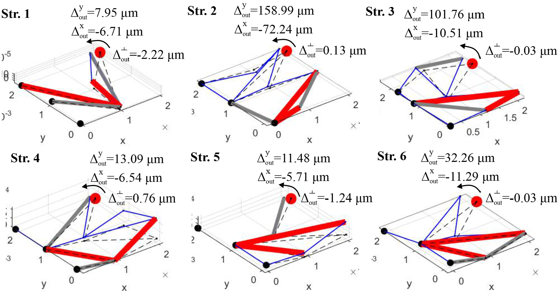
Optimal solutions of the micro-robotic appendage synthesis for the end-effector control in X + Y direction in-plane, shown in active-deformed position (initial position is shown with dash lines); deformations are scaled for clarity. Candidate elements: parylene-C (soft), Si (rigid) and thin-film PZT (active). Elements that are on both ends connected to the fix nodes do not contribute to the appendage motion.
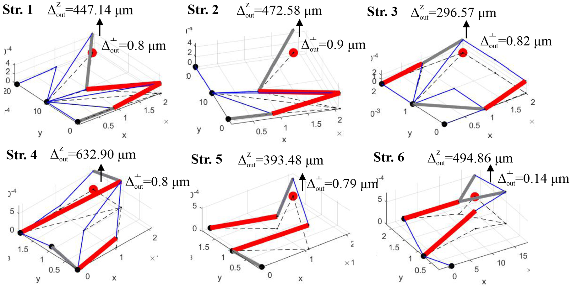
Optimal solutions of the micro-robotic appendage synthesis for the end-effector control in Z direction out-of-plane, shown in active-deformed position (initial position is shown with dash lines); deformations are scaled for clarity. Candidate elements: parylene-C (soft), Si (rigid) and thin-film PZT (active). Elements that are on both ends connected to the fix nodes do not contribute to the appendage motion.
Weighting constants and specific design parameters used for the synthesis of the micro-robotic appendages optimizing motion in one direction.
All the micro-robotic appendage designs achieve desired directional control of the end-effector: solutions in Figure 11 realize nearly pure linear motion in the Y direction; in Figure 12, general in-plane motion with limited out-of-plane displacement; and in Figure 13 out-of-plane motion with low off-axis translation. Different ranges of end-effector displacement are achieved with different topologies/designs of the micro-robotic appendages. Of special interest are:
Figure 14(a) shows a comparation between the appendage designs with respect to end-effector displacement per volt, total PZT area, and total density of structures (sum of the length of all the elements in design topology). Figure 14(b), shows a similar comparison but considering payload capacity based on out-of-plane stiffness. Unsurprisingly for a piezoelectric system, under many weightings of the objective displacement is small relative to overall design length, but some designs do extend into larger displacements, associated with a modest increase in PZT and generally, not universally, reduced out-of-plane stiffness. Such designs will be the focus of further discussion in section 5.
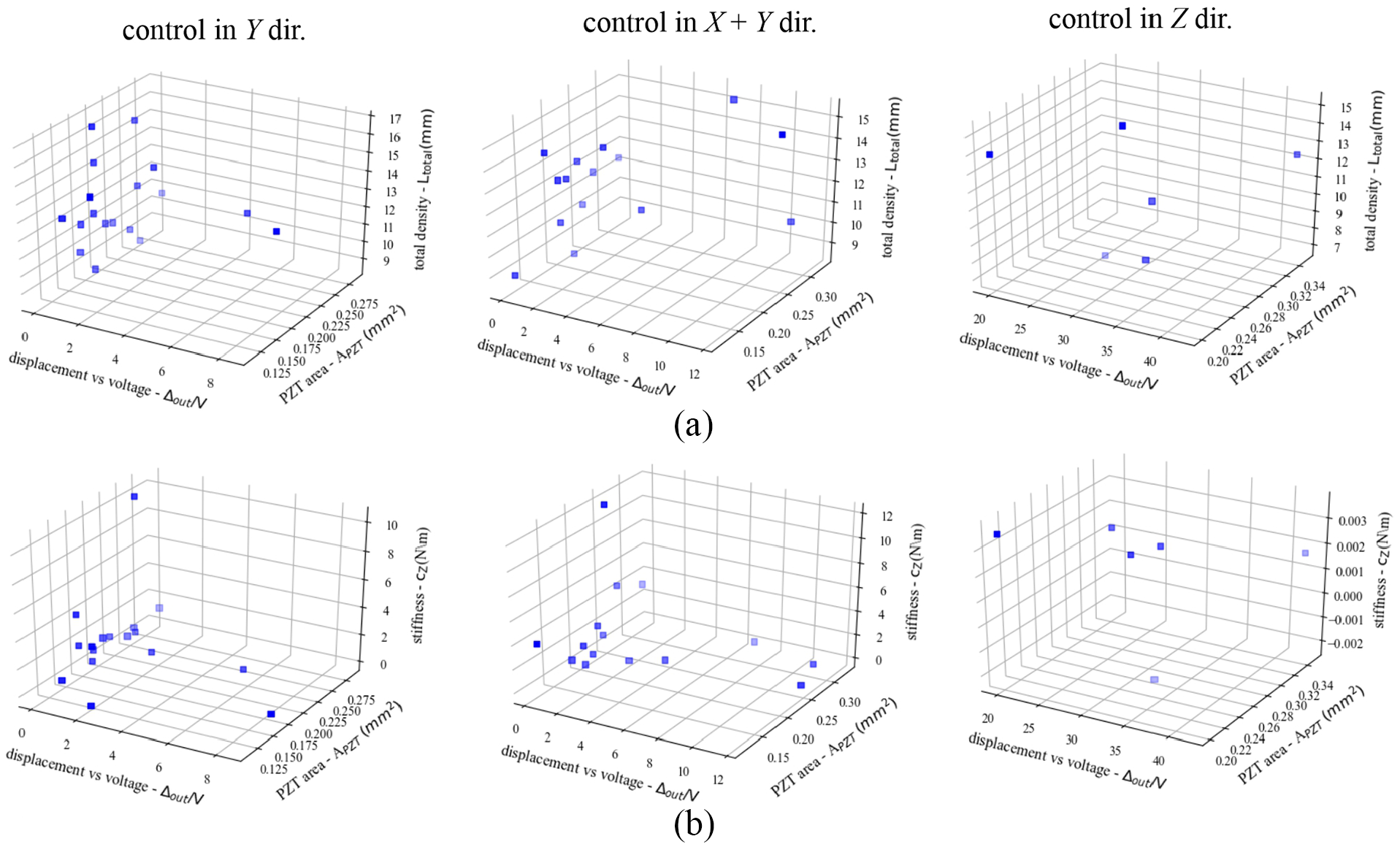
Comparation between the obtained solution of the micro-robotic appendages for end-effector control in one direction, considering parameters: (a) end-effector displacement versus input voltage, total PZT area, and total density of structures; and (b) end-effector displacement vs input voltage, total PZT area, and out-of-plane stiffness.
3.2. Micro-robotic appendage designs for end-effector control in two directions
Figure 15 shows results for micro-robotic appendages that can realize control of the end-effector in two directions. Designs are presented for the following synthesis case: a rectilinear design domain with parylene-C (soft), Si (rigid), and thin-film PZT (active) material set, with end-effector control in X + Y (in-plane), and Z (out-of-plane) direction.
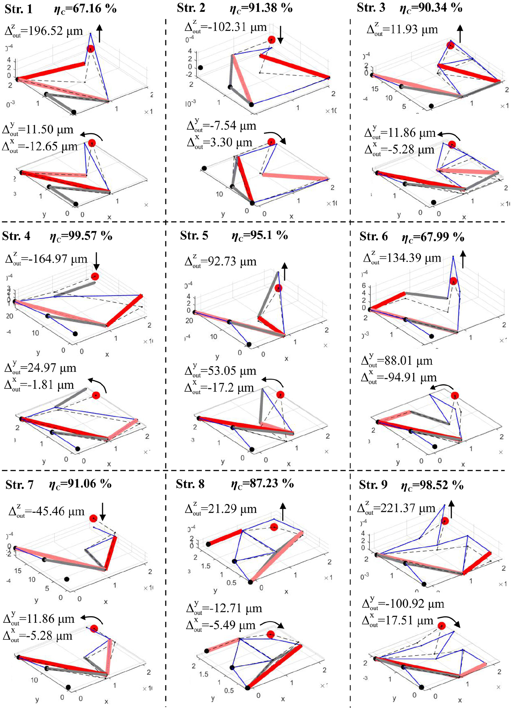
Optimal topologies of the micro-robotic appendage designs for end-effector control in two directions; deformations are scaled for clarity. Candidate elements: parylene-C (soft), Si (rigid) and thin-film PZT (active). Elements that are on both ends connected to the fix nodes do not contribute to the appendage motion.
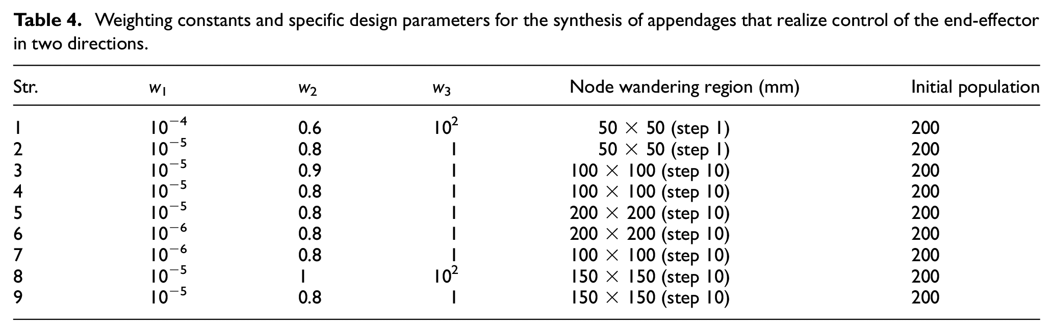
Again, multiple results are obtained for different initial sets of parameters (nodal connectivity, range of node wandering, values of weighting constants wc, Tables 1 and 4). Most appendage designs achieve a high value of end-effector controllability, with relatively large end-effector displacement. Interesting results include:
Weighting constants and specific design parameters for the synthesis of appendages that realize control of the end-effector in two directions.
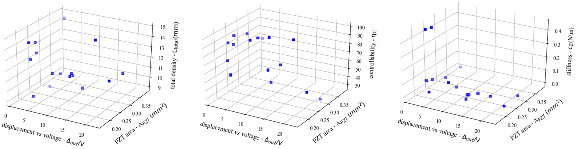
Comparation between the obtained solution of the micro-robotic appendages for end-effector control in two directions, considering performance objectives of: (a) total end-effector displacement per volt, total PZT area, and density of structures; (b) total end-effector displacement per volt, total PZT area, and controllability; and (c) total end-effector displacement per volt, total PZT area, and out-of-plane stiffness.
4. Finite element method characterization of micro-robotic appendages designs
To further investigate the deformation behavior of the micro-robotic appendage designs and validate the obtained solutions (Figures 11 to 13 and 15), a nonlinear Finite Element Method (FEM) analysis is realized using commercially available FEM software (Comosl Multiphysics). Simulations are realized for different appendage designs, with select results presented here.
4.1. Finite Element Method analysis setup
The FEM analysis setup is explained using a representative example (Figure 17). From synthesis-optimized solutions (Figures 11 to 13 and 15), a solid 3D model of the appendage is defined considering MEMS fabrication requirements (Figure 17(a)). More specifically, the appendage solution is designed to resemble the prototype that would be produced. Thus, the appendage is comprised of (Figure 17(b)):
Parylene-C elements (T and L type), denoted in blue,
Si elements, with SiO2 trenches, denoted in gray,
Thin-film PZT comprised of four material layers, bottom-SiO2 (green), middle-PZT (red), top second-Au (orange), and top first-parylene-C (purple).
For the FEM simulation, structural mechanics are coupled to the piezoelectric device module in Comsol. Fixed supports are applied at the same location as in the optimization (Figure 11). PZT-5H material is used, applied from the Comsol library (Figure 17(a)), with voltage adjusted to account for differences with thin-film PZT piezoelectric coefficients, that is, the d31ã¡V product for internal axial strain modeling in the piezoelectric elements is kept as consistent as possible between optimization and FEA. This does not fully reproduce thin-film PZT piezoelectric properties but captures dominant effects in narrow beam geometries. Electric potential is applied across the top and bottom surfaces of the PZT (Figure 17(b)). Other materials use the same material properties as in Table 1. The mesh model of the appendage is shown in (Figure 17(c)). A similar FEM setup is realized for other appendage design solutions, where for control in two directions, a separate FEM simulation is run for each of the active thin-film PZT.
(a) Solid 3D model of the micro-robotic appendage; (b) finite element method simulation setup; and (c) mesh model of the appendage.
4.2. Deformation behavior of appendage designs for control in one direction
Figure 18 shows initial models and resulting deformation behavior of the micro-robotic appendages for end-effector control in one direction when all PZT’s are activated. The results are presented for the few selected designs including the rectilinear design domain with:
Control in the Y direction (in-plane)—Figure 18(a)
Control in the X + Y direction (in-plane)—Figure 18(b)
Control in the Z direction (out-of-plane)—Figure 18(c)
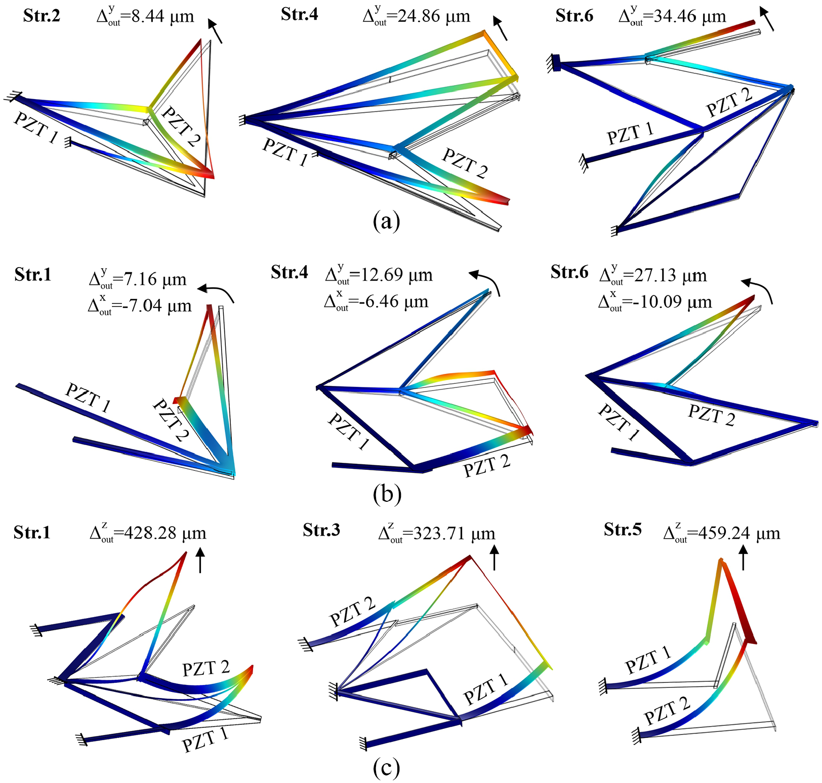
Results of the FEM investigations of the micro-robotic appendage deformation behavior when thin-film PZT’s are activated: (a) end-effector control in in-plane (Y); (b) end-effector control in in-plane (X + Y); (c) end-effector control in the out-of-plane (Z); deformations are scaled for clarity. Candidate elements: parylene-C (soft), Si (rigid) and thin-film PZT (active).
Results show that appendages modeled in 3D FEA realize the desired motion direction for the end-effector. Good agreement with the linear optimization is achieved (Figure 19). Despite approximations in optimization modeling, such as the simplified PZT model (d31 only), linear beam assumptions, and point connections between elements (simplification in the connection between different candidate material sets), the nonlinear FEM results show that the designs realize similar deformation with a similar range of end-effector motions when modeled to reflect geometries as they would be fabricated. However, we note that for some structures with very large deflections out-of-plane (Figure 18(c) and Str.1-Z, Str.3-Z, Str.5-Z in Figure 19), there is some small difference with the optimization. We attribute this to the material nonlinear effects that are more expressed in these structures when very large deflections are realized. This may lead to additional differences between optimization and FEM results in those cases.
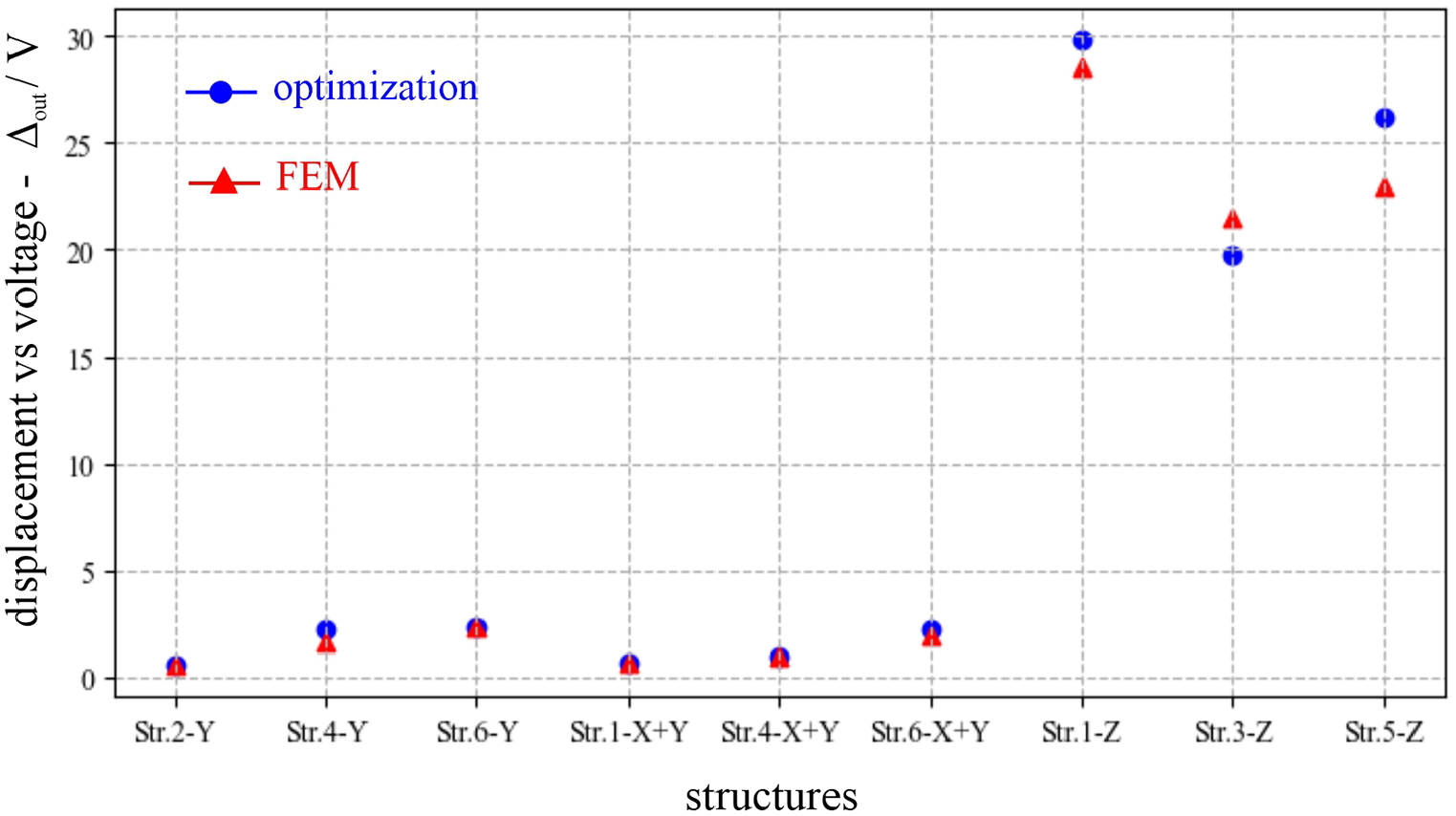
Comparison between micro-robotic appendage designs for end-effector control in one direction, realized with optimization and modeled with commercially available software using nonlinear FEM.
4.3. Deformation behavior of appendage designs for control in two directions
Figure 20 shows initial models and resulting deformation behavior of the micro-robotic appendages for end-effector control in two directions. Again, directional control of the end-effector is achieved when different thin-film PZT’s are activated. Similar ranges of motion are realized as in the optimization (Figures 15 and 21), this is especially the case for realizing in-plane motion. In many cases, the structures realize even larger end-effector displacement than the ones from optimization, which could be considered advantageously (Figures 15 and 20). As an example,
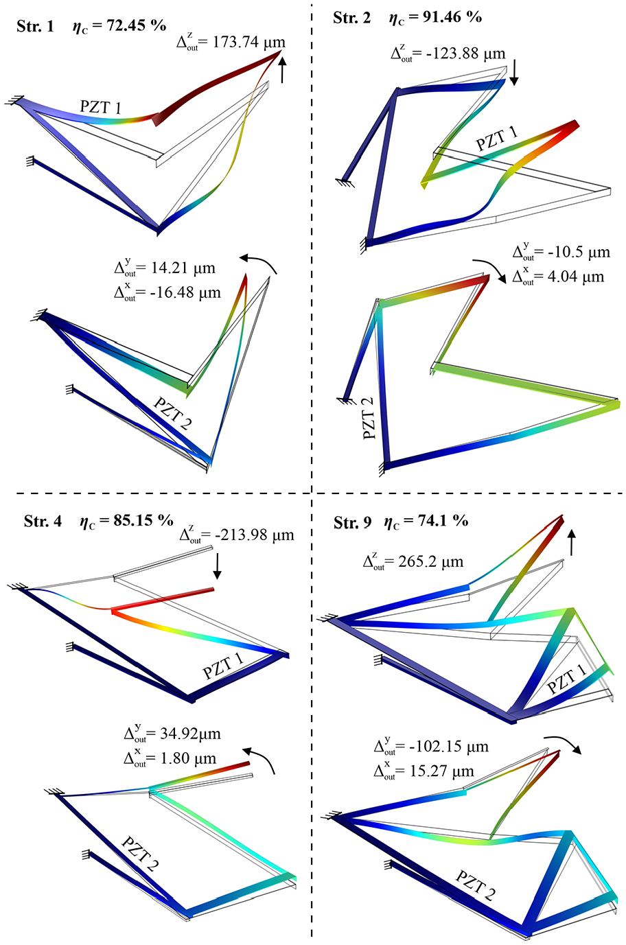
Results of the FEM investigations of the micro-robotic appendage deformation behavior for the end-effector control in two directions (out-of-plane and in-plane). Appendage behavior when thin-film PZT 1 is active (left) and when thin-film PZT 2 is active (right); deformations are scaled for clarity. Candidate elements: parylene-C (soft), Si (rigid) and thin-film PZT (active).
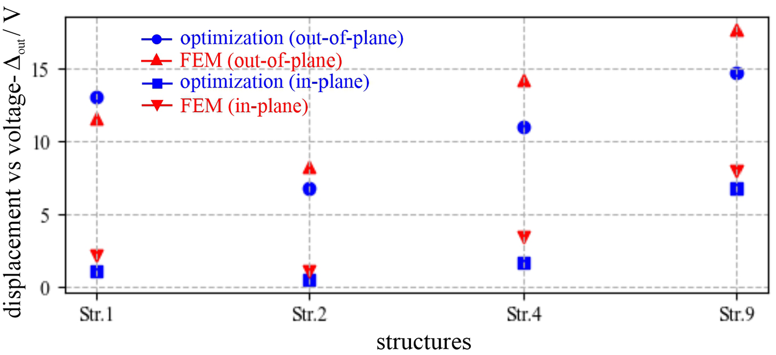
Comparison between micro-robotic appendage designs for end-effector control in two directions realized with optimization and modeled with commercially available software using nonlinear FEM.
There are some differences in the realized value of controllably between optimization and modeled designs (although still relatively high values of controllability are obtained with respect to the achieved range of motions), compared to single-axis motion. This is because when the PZT controlling out-of-plane motion is active, designs realize a larger in-plane displacement than predicted in linear modeling, which has a great effect on the micro-robot appendage controllably. The controllability is highly sensitive to even small changes in the end-effector displacement values (even changes in second decimal values), but good results are achieved compared with a large displacement of end-effector, especially in the out-of-plane direction. In general, viable solutions are realized with promising results as in
5. Discussion of results
Results of design for pure in-plane motion, either constrained to a specified axis (control in Y-direction, Figure 11) or general in-plane motion (Figure 12) illustrate several representative trends. Low-displacement structures (i.e. Figure 11,
Large displacement structures present the greatest opportunity for innovating on past piezoelectric actuator design, and in this context, the synthesis optimization produces novel combinations of large displacement with reasonable out-of-plane stiffness (i.e. load-bearing capacity) relative to prior literature. While reporting on thin-film piezoelectric actuator specifications in multiple axes is limited, Table 5 compares proposed designs to a selection of prior designs (material properties used in this study being derived from (Choi et al., 2017)). Proposed optimized designs provide nearly the largest displacements per volt anticipated among thin-film PZT mechanisms at the millimeter scale, versus (Edamana et al., 2011), with approximately an order-of-magnitude increase in out-of-plane stiffness and limited PZT element area; both improvements are highly desirable for ultra-low-power, autonomous robotic operation. In contrast, high-stiffness thin-film PZT actuators in past literature achieve much smaller displacements despite the much larger total area, also usually requiring substantially larger quantities of PZT (Fujimura et al., 2018; Hida et al., 2016).
Comparison between prior thin-film piezoelectric robotic appendage designs from literature and designs realized through the proposed synthesis method.
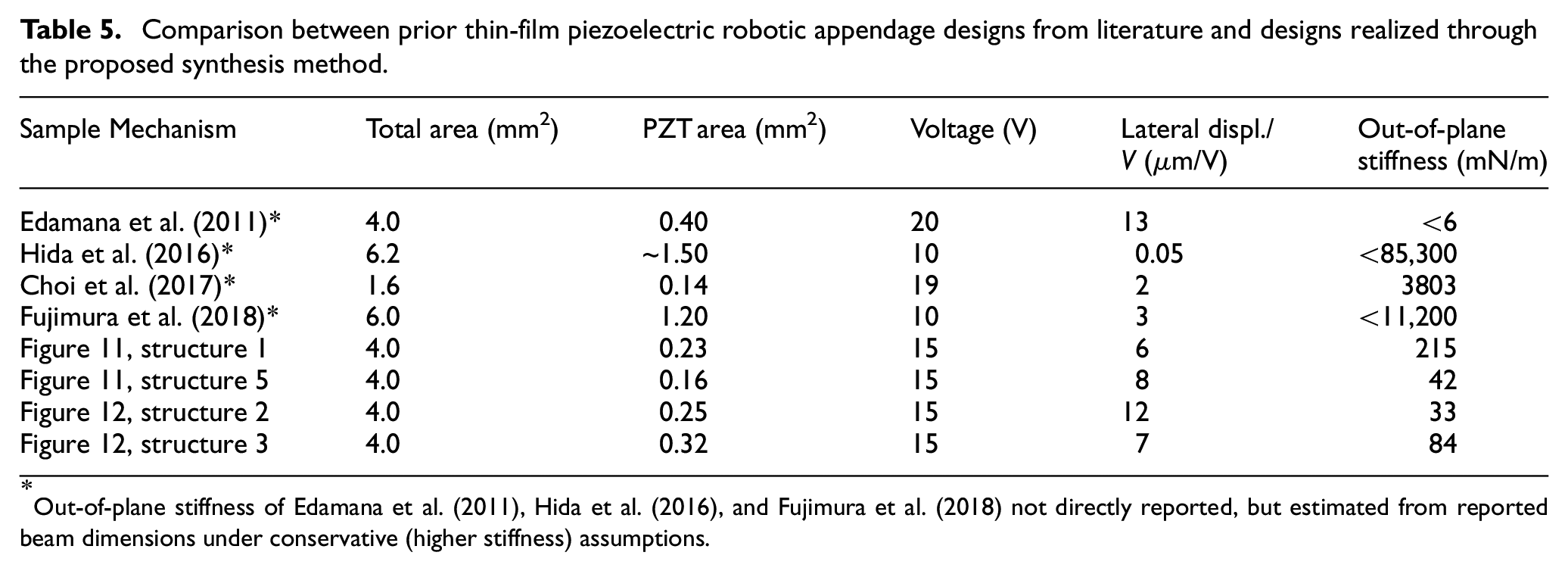
Out-of-plane stiffness of Edamana et al. (2011), Hida et al. (2016), and Fujimura et al. (2018) not directly reported, but estimated from reported beam dimensions under conservative (higher stiffness) assumptions.
Innovative features of actuator design for out-of-plane motion are limitation of off-axis motion despite asymmetric design (end-effector at a distance from the base), and, in certain designs, generation of displacement in a manner approximating out-of-plane rotation. In practice, pure vertical motion of a micro-robotic end-effector is less useful for locomotion than in-plane or multi-axis designs, and vertical motion can be readily generated by basic thin-film PZT cantilevers. Nonetheless, the proposed optimization procedure produces designs with very low off-axis translation (∼1 µm under linear beam model, ∼10 µm in 3D FEA) over several hundred microns of out-of-plane motion. This type of vertical motion usually requires symmetric actuation around a central stage. In many optimized designs (i.e. Figure 13,
In many obtained micro-robotic appendages solutions (Figures 11 to 13), the thin-film PZT are not directly connected with the end-effector point, but the rather topological distribution of other elements (parylene-C and Si) is utilized to realize desired motion, which is one more advantage of the proposed synthesis framework. Interestingly for some of the micro-robotic appendages designs, optimization decided not to utilize fully available candidate material sets. In
Designs that can achieve controllable 2-axis motion demonstrate the concept of topology optimization to decouple multi-axis motion with high-performance. While micro-robotic locomotion does not strictly require decoupled motion in two axes, such designs can simplify active control and be highly desirable in micro-manipulation tasks. Meanwhile, substantial in-plane and out-of-plane motion, with the ability to adapt effort between them, can be desirable for micro-robotic locomotion on complex terrain. In most optimized designs, we observe a tendency to locate a large piezoelectric effort, controlling in-plane motion, near the anchors of the mechanism to leverage an in-plane rotation into large end-effector displacement. Meanwhile, a smaller, intermediate actuator controls out-of-plane displacement. This is reminiscent of bio-inspired micro-robot leg designs, but with a much greater diversity of candidate designs and reduced sensitivity to residual stresses.
Overall, while there are fundamental trade-offs in displacement versus stiffness that constrain performance for any transduction mechanism, the topology optimization and synthesis identify feasible solutions for thin-film PZT actuation that are not well represented in existing technologies.
From a fabrication perspective, innovations in a synthesis that consider the specific beam elements and cross-sections that have been fabricated in past work and novel geometric filtering to eliminate overlapping designs facilitate feasible solution generation. Final geometries are based on the planar, layer-by-layer geometries most easily fabricated with thin-film PZT (as in (Choi et al., 2017)), with FEA analysis providing reasonable confidence that idealized behaviors in the optimization (point connections between beams, simplified piezoelectric model) do not produce an excessive error. Aspects of fabrication that are not fully represented are variability in device properties, particularly piezoelectric coefficients, and residual stress. Nonetheless, the largest impact of these uncertainties is on maximum displacement, as opposed to the nature of active displacement (i.e. in-plane vs out-of-plane, degree of controllability). Future work might consider the robustness of proposed designs under parameter perturbations.
6. Conclusions
This paper has described a novel approach for designing multi-material micro-robotic appendages, incorporating diverse material sets from modern microsystem fabrication. Such a synthesis approach has not been introduced before for the design of terrestrial MEMS micro-robots, while as a structural optimization problem, the proposed approach uniquely incorporates passive soft/compliant, rigid, and active elements (as well as active element orientation, dimensions, etc.) into a single 3D, multiple-input optimization problem. Many objectives can be optimized, but we focus on design for controllable motion in one or more specified axes, subject to potential external loads and residual stress effects. This allows the strength of this procedure in managing multiple objectives to be illustrated. Sample designs for micro-robotic appendages obtained by this method incorporate several interesting features. Examples include:
Large in-plane displacements (exceeding 100 µm) with small PZT working area and comparatively large stiffness for the range-of-motion and actuator size,
Large out-of-plane displacements (several 100s of µm) with a limited off-axis motion from a distal anchor point, without need for symmetric actuation about the end-effector,
Out-of-plane displacement from designs with approximately rigid-body rotation generated by derived from planar thin-film PZT actuation elements,
Highly-decoupled axes of motion in multi-axis design scenarios.
Limitations of this work include the complexity of ensuring appendage optimization is well aligned with systematic needs, and of the structural optimization process itself. The optimization method can effectively translate the specified motion and stiffness characteristics anticipated to be desirable for micro-robot locomotion, and place actuation elements and other micro-structures appropriately. However, this abstracts desirable motion characteristics to a systemic analysis level not currently examined; future work will consider optimization functions based on system-level considerations such as cost-of-transport was given constraints such as power source energy density. Meanwhile, the complexity of the optimization procedure, using genetic algorithms with many continuous and discrete parameters, can make designs highly sensitive to the weighting of elements in an objective function and problem set-up. This can be advantageous, in generating design concepts that would not easily be developed by other means, but also requires some guidance by the designer to adjust cost function weighting in the current approach.
In a broader sense, application of the evolutionary GA may lead to the realization of evolutionary robotics, where micro-robotic designs are realized thought the process of evolution and natural selection, like organism evolution over time. This can potentially reveal many interesting designs solution, that was not previously recognized or consider possible by design with human intuition and experience. This may facilitate new research where micro-robots are primally designed via optimization algorithms and through automated processes that do not include a human in the loop.
Future work will also include fabrication of the micro-robotic appendages, testing, and experimental verification of the results presented in the paper.
Footnotes
Acknowledgements
The authors thank Dr. Jongsoo Choi for sample images of integrated silicon-polymer-PZT robots and actuators.
Declaration of conflicting interests
The author(s) declared no potential conflicts of interest with respect to the research, authorship, and/or publication of this article.
Funding
The author(s) disclosed receipt of the following financial support for the research, authorship, and/or publication of this article: This work was supported by the Academy of Finland Research Council for Natural Sciences and Engineering [grant number. 318390] and National Science Foundation grant IIS 1208233, with additional support from the University of Michigan.