
Abstract
Fish Cells as a new metamaterial with zero Poisson’s ratio in two planar directions is introduced with application in morphing aircraft skin. In order to tailor the design of this metamaterial for arbitrary loadings, equivalent elastic properties of the Fish Cells metamaterial are derived and analyzed using analytical and numerical methods. The admissible range of geometric parameters is presented and variation of elastic properties with parameters is studied. The effective elastic modulus of the metamaterial is derived analytically and verified with finite element models. The in-plane and transverse shear modulus of the metamaterial are evaluated using finite element analysis where accurate periodic boundary conditions for in-plane shear loading are investigated. The lower and upper bounds of the transverse shear modulus are derived based on strain and complementary energy relations which are verified with finite element results. As zero Poisson’s ratio behavior of the Fish Cells topology is proved, derivative geometries from this topology with zero Poisson’s ratio behavior are also presented.
1. Introduction
Cellular materials have received extensive attention in the aerospace engineering applications due to their high performance and low density. Considering improved functionality of the aerospace structures, mechanical metamaterials and their exotic properties have attracted interest in their design and development. The aim of metamaterial design is tailoring specific properties such as bulk modulus, elastic modulus, Poisson’s ratio, and coefficient of thermal expansion. Many of these mechanical metamaterials possess cellular architecture while the geometry of the unit cell is tailored to result in a desired deformed shape under loading which allows for exotic behavior in macroscale. Among mechanical metamaterials, those focused on Poisson’s ratio are zero Poisson’s ratio (ZPR) metamaterials and auxetic metamaterials with negative Poisson’s ratio (NPR). ZPR is of particular interest given their useful applications in morphing skin’s core. The optimal design of these cores requires simple models of the metamaterial that may be incorporated into multidisciplinary system models. Therefore, equivalent structural models are required that retain the dependence on the geometric parameters of the metamaterial.
Due to the high demand for cellular structures, previous studies have led to many analytical and numerical models. The focus of these studies has been to develop analytical formulations or a numerical homogenization framework for equivalent elastic properties of cellular structures based on their geometrical parameters. The main approach for modeling the elastic properties of cellular materials has been energy method where strain energy is developed for each member of the unit cell under loading in each direction (Abd El-Sayed et al., 1979). Having the displacements of the cell measured using the energy method under a specific load, the equivalent elastic modulus in that direction can be obtained. The formulation of the modulus obtained using this method is dependent on the deformation mechanism considered, for example, the inclined members of the honeycomb unit cell can be considered as a cantilever beam with bending as the primary mechanism (Gibson et al., 1982) or also account for extension and hinging (Masters and Evans, 1996). Beam model can simplify the equivalent modulus derivation. However, it is accurate enough when cellular structure’s relative density is low and the effect of joints at the intersection of inclined members of a cellular structure such as honeycomb is not significant (Malek and Gibson, 2015). Although the beam model is acceptable for low relative density cellular structures, modification of the member’s effective length can help to improve the results (Grima et al., 2011). Similar to beam, if thickness to length ratio of members is not small enough, shell model also results in different in-plane elastic properties comparing to three-dimensional (3D) or plane stress models due to the negligence of the out of plane stress in shell walls (Catapano and Montemurro, 2014). In this regard, slender members should be considered to keep the density low and be able to neglect the effect of joints. Therefore, the beam model can be used to derive the equivalent elastic modulus of the metamaterials that bending is their dominant deformation mechanism.
Shear modulus derivation is more complicated than elastic modulus in two orthogonal directions of the metamaterial. The first parameter to consider for the correct derivation of the shear modulus is the type of shear loading which can be simple or pure shear. Applying simple shear in two orthogonal directions results in two different equivalent shear modulus when the material lacks symmetry because of different deformations in the unit cell. The discussion of the simple and pure shear for different categories of materials is complex and less investigated in the literature. It is shown that simple and pure shear cannot be considered as equivalent (Destrade et al., 2012). To obtain the shear modulus of the hexagonal honeycomb, Gibson (1989; Gibson et al., 1982) has considered the pure shear loading where bending was considered as the main deformation mechanism for each member of the cell. If the simple shear loading on the honeycomb is considered, then loading in two orthogonal directions should be considered (Chen et al., 2016), which technically means Gxy≠Gyx.
For cellular metamaterials also similar approach like honeycombs has been followed for shear analysis. Ju et al. (2011) studied the re-entrant cellular material under simple shear loading with several geometrical parameters in order to find the best yield strength for a predefined equivalent shear modulus. Their results show that shear resistance was independent of the Poisson’s ratio value but dependent on the cell topology. In another attempt, Huang et al. (2017) considered re-entrant cell with a thin plate attached and calculated the shear modulus by application of pure shear loading where bending of the members is considered using Timoshenko beam theory to derive the closed form equation for shear modulus. Similarly, for ZPR cellular metamaterials with orthotropic cell topology, pure shear loading is applied and bending as the main deformation of the members was considered to derive the equivalent shear modulus formulae (Gong et al., 2015; Liu et al., 2019).
In this article, a new metamaterial called Fish Cells with ZPR in two planar directions is introduced and its equivalent elastic properties are investigated. The importance of a homogenized equivalent model for elastic properties is in reducing the time to model and analyze the structure significantly while maintaining the accuracy level (Steenackers et al., 2016). The in-plane and out of plane equivalent elastic modulus and in-plane shear modulus of the Fish Cell are obtained by considering small deformations of a two-dimensional (2D) unit cell, in which the members will be modeled as thin beams. The importance of representative volume element (RVE) selection and periodic boundary conditions (PBCs) in the shear analysis is discussed and pure shear analysis on the material is performed. Due to the complexity of the structure and boundary conditions in shear loading, the finite element (FE) method is employed to obtain the equivalent in-plane shear modulus. Finally, the effect of geometrical parameters of the Fish Cell on equivalent elastic properties is studied. The importance of this work is to provide an equivalent model which uses the geometric parameters of the Fish Cells metamaterial as variables and obtains equivalent elastic properties that can be applied for further optimization studies.
2. Equivalent elastic modulus
The unit cell of the Fish Cells metamaterial is shown in Figure 1(a), which satisfies the periodicity conditions to create a tessellation. The unit cell is formed by two Fish Cells that are attached together followed by a rotation. Fish Cell, as shown in Figure 1(b), has been introduced by one axis of symmetry along which the cell can be assembled periodically but in the normal direction, the cell should rotate or shift to assemble. Although Fish Cell is the basis of the metamaterial design, the unit cell is selected in a way to satisfy periodicity in both in-plane orthogonal directions and appropriate boundary conditions can be applied considering symmetries (Li, 2008).
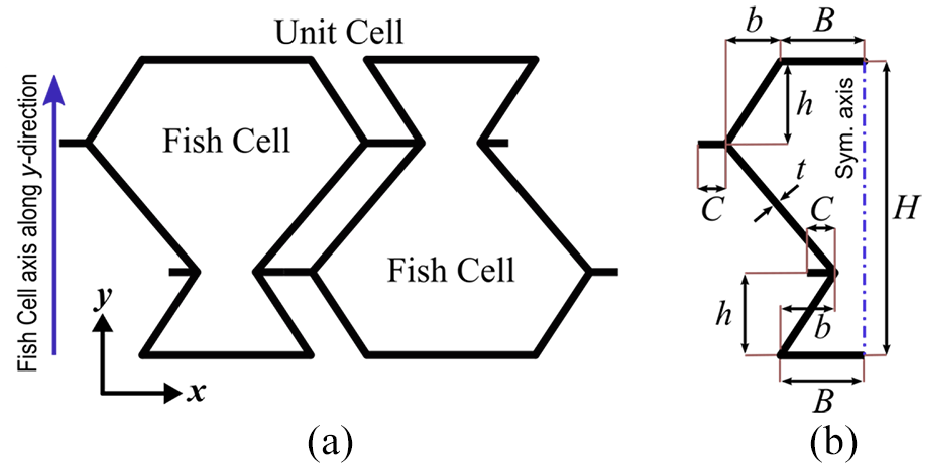
(a) Unit cell of the Fish Cells metamaterial and (b) Fish Cell parameters’ definition.
Fish Cell configuration is defined by independent parameters B, H, C, h, and b, where B is the half base length, H is the height of the cell, and C is connector’s length. Parameters b and h are horizontal and vertical components of the inclined rib’s length, respectively. It should be noted that half thickness is allocated to the base of the cell that creates a full thickness member in tessellation. The feasible range for b and h is described in equations (1) and (2). Uniform rectangular cross section is assigned to all members with thickness t and extruded out of plane thickness W
2.1. Loading in the x-direction
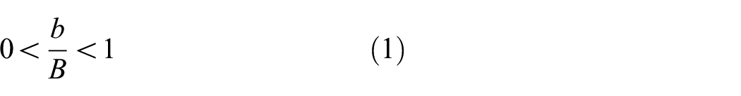
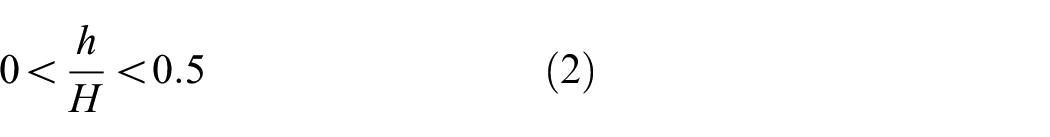
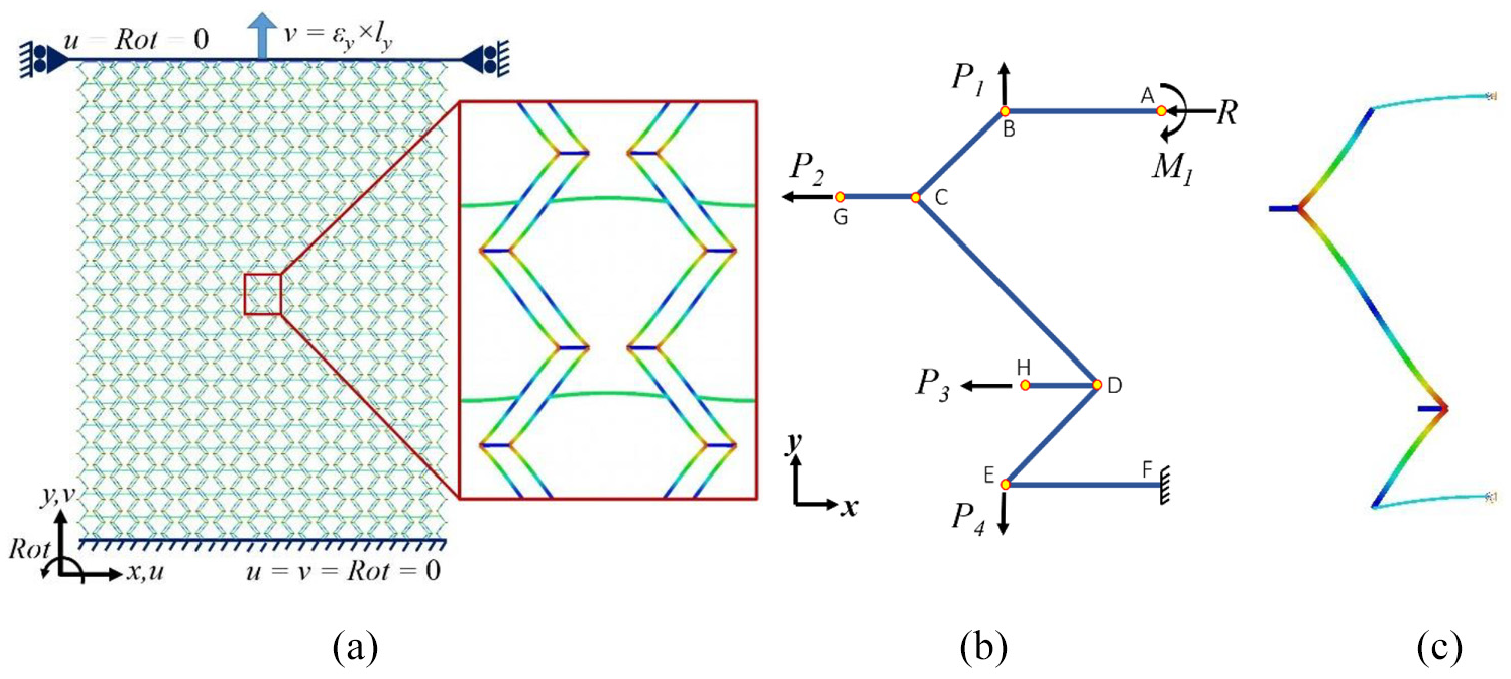
As detailed in Part I (companion) of this article, the main deformation in the unit cell under tension in the x-direction occurs in the inclined members where the convex section of the Fish Cell contracts and the concave section expands in the y-direction. The deformed shape of the cell in the middle of a tessellation is shown in Figure 2(a) where FE analysis using beam elements with parameters discussed in companion paper was conducted. The base of the Fish Cell experiences no bending as moments exerted by inclined members on the base member neutralize each other. This simplifies the model required for bending analysis by neglecting the base member. Considering the symmetry of Fish Cell as shown in Figure 2(a), half of one Fish Cell can be modeled as a representative for the unit cell under loading in the x-direction.
(a) Deformed shape of the Fish Cell in a tessellation under loading along the x-direction, (b) free body diagram of half Fish Cell, and (c) deformed shape of the half Fish Cell obtained from FE analysis.
A diagram of this model is presented in Figure 2(b) where loads and reactions are depicted based on the deformation of a cell in tessellation. The accurate boundary condition type for periodic cellular structures is PBC (Xia et al., 2003, 2006). However, for normal in-plane loadings, using homogenized boundary conditions that set the value of a degree of freedom equal to 0 does not affect the deformed shape adversely and results verify with those obtained from tessellation. Moreover, Castigliano’s theorem can be used to derive a closed form solution for the equivalent elastic modulus. The boundary conditions and loading for the half Fish Cell shown in Figure 2(b) are defined in Table 1. Displacements in the x-direction at nodes “F” and “A” are constrained because of the symmetry and a reaction load is considered at node “A” due to the support. Displacement in the y-direction at node “F” is also constrained to prevent rigid body motion, while node “A” is free to move in the y-direction. Since base members of the cell (AB and EF) experience no bending moment, rotation of the node “E” is constrained and a reaction moment is applied at node “B.” Rotations of the nodes “G” and “H” are also zero where reaction moments are imposed to enable derivation of the total strain energy of the half-cell. In order to calculate the lateral displacement in y-direction using Castigliano’s theorem, which helps to derive the Poisson’s ratio, P1 and P4 are applied as virtual loads. To verify the boundary conditions used in the analytical model, FE analysis is performed by ABAQUS on the half Fish Cell where fine mesh using quadratic shear deformable beam elements B22 was employed. The deformed shape of the half Fish Cell is in agreement with the deformed shape of a half Fish Cell in tessellation as depicted in Figure 2(c) where boundary conditions of Table 1 were imposed.
Boundary conditions applied on half Fish Cell in FE analysis under loading in the x-direction.
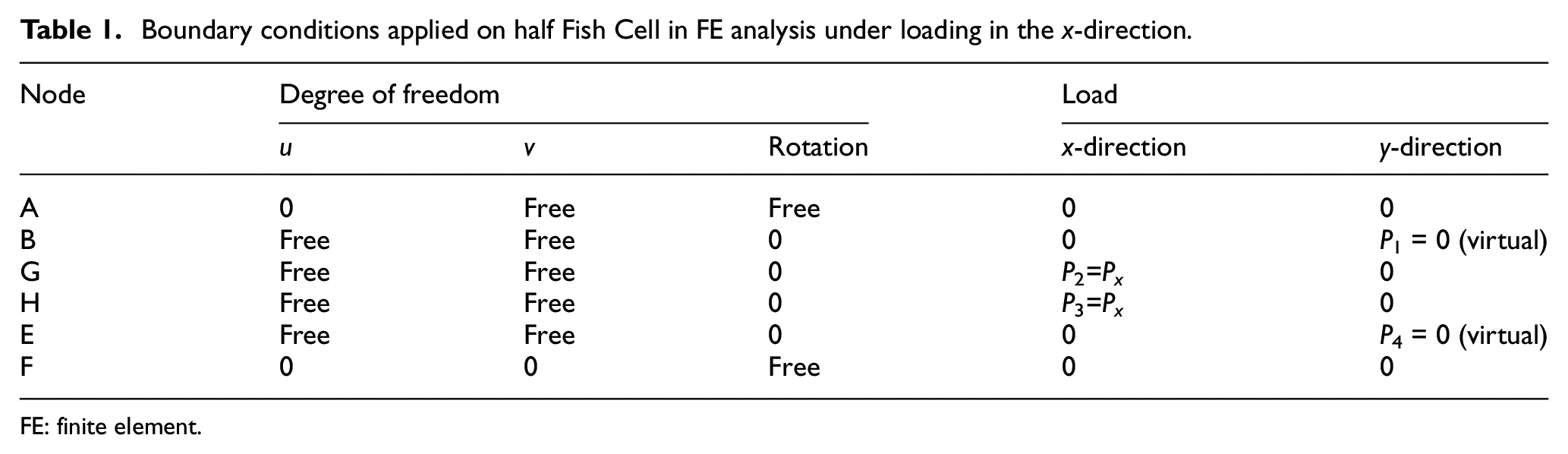
FE: finite element.
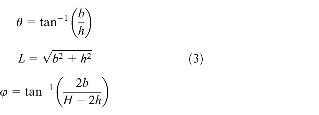
Since equilibrium equations should be written for each member, local parameters are defined for inclined members to simplify the equations. Parameter θ is defined as the angle between inclined ribs and y-direction as shown in Figure 2(b). Length of the two bending ribs connected to the base members (AB and DF) is assumed L and for the middle rib “CD,” the length is D. The angle between the middle rib and y-direction is also called φ. However, length D is a dependent parameter with respect to L, θ, and φ as
Starting from node “B,” the bending moment of each member can be written as in equation (A-1) in Supplemental Appendix A while there is no moment on members “AB” and “EF.” Similarly, the axial force at each member can be derived as in equation (A-2) in Supplemental Appendix A. Using forces and moments at each member, the total strain energy is obtained as in equation (A-3) in Supplemental Appendix A, where bending and stretching of the members are considered. Bending is the main deformation mechanism that contributes the most to the total energy comparing to the axial deformation. Since very thin members are considered, the effect of shear deformation is neglected. The contribution of axial loads and bending moments to the strain energy is written in equation (A-3), where Es is the constructing material modulus and moment of inertia I = Wt3/12. Uniform rectangular cross-section with area At is assigned to each inclined member and connectors where At=W×t. Since the base members of the Fish Cell are shared between two cells, half of the thickness is allocated for the base members in each cell, which affects the axial term of the base members’ strain energy denoted by subscript t/2 where At/2 = W×t/2 as shown in equation (A-3).
The deformation corresponding to each load can be obtained using Castigliano’s theorem by derivation of total energy function with respect to that load. Since node “A” has no displacement in x-direction due to symmetry condition, the total energy derivation with respect to load R is zero, which concludes equation (A-4). Rotations at nodes “B,”“G,” and “H” are also zero, which result in equation (A-5). Loads P2 and P3 are equal due to periodicity and are assigned with a constant value Px. Expanding equation (A-4) and substituting P2 and P3 with Px results in R=−Px. Substituting these values in equation (A-5), the unknown reaction moments are obtained as in equations (A-6) and (A-7) in Supplemental Appendix A.
2.1.1. Equivalent elastic modulus
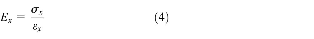
Using Hooke’s law, the equivalent elastic modulus of the homogenized Fish Cells metamaterial in the x-direction is obtained by the ratio of stress to strain as
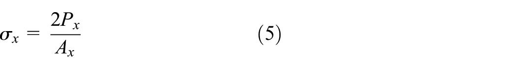
The stress σx is equal to the total force in x-direction divided by the effective area Ax=W×H
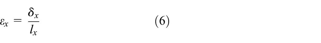
The strain εx is equal to the displacement in x-direction divided by the effective length lx=B+C
Displacement δx is obtained by calculating strain energy and applying Castigliano’s theorem to the load P2, as indicated in equation (7). The displacements due to P2 and P3 have the same value in the x-direction; therefore, derivation with respect to P2 will be
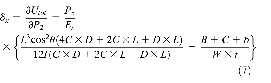
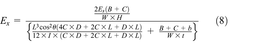
Combining equations (4) to (7) leads to the closed form solution for the equivalent elastic modulus in the x-direction as obtained in equation (8). It is evident that equivalent modulus relation is independent of the load Px because the load term in σx is omitted by the load term in δx
Elastic modulus obtained by analytical model from equation (8) for a Fish Cell with B = 8 mm, H = 24 mm, h = 6 mm, b = 6 mm, C = 2 mm, W = 1 mm, and t = 0.1 mm is compared with FE analysis results in Table 2 for both unit cell and tessellation. The relative error relation is
Elastic modulus of the Fish Cell metamaterial normalized by constitutive material modulus Es, obtained using FE and analytical methods.
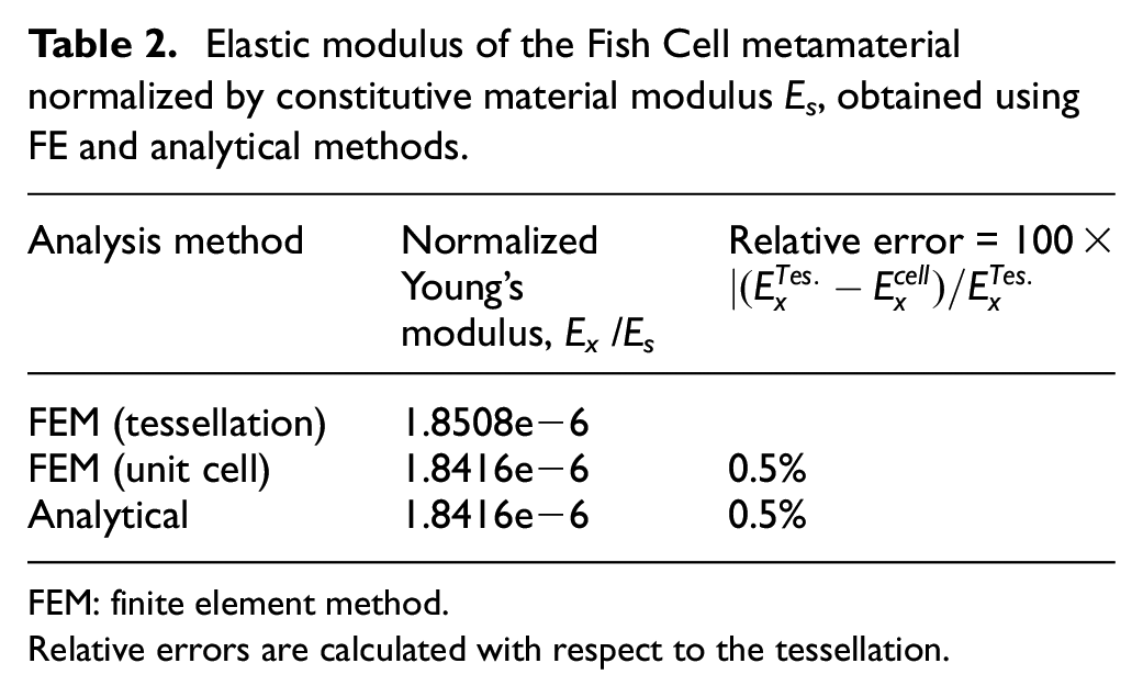
FEM: finite element method.
Relative errors are calculated with respect to the tessellation.
Using equation (7), the effect of geometrical parameters on elastic modulus is studied where aspect ratio (H/B) of the Fish Cell and three normalized parameters h/H, b/B, and C/B are considered. Results are shown in Figure 3 where elastic modulus Ex is normalized with respect to the constructing material modulus Es where FE analysis is also used to validate the trend obtained. Two parameters, which cause large changes in modulus from orders of magnitude, are aspect ratio and the vertical component of rib’s length as shown in Figure 3(a). This large effect of the vertical component of rib’s length is because it acts as the moment arm of the load Px. Equivalent elastic modulus in x-direction reduces by increasing both the vertical component of rib’s length and aspect ratio because of the moment arm increase. Variation of the modulus with the horizontal component of the rib’s length and connector’s length is from the same order of magnitude as shown in Figure 3(b). The equivalent modulus reduces by increasing the horizontal component of rib’s length since the beam stiffness reduces by increasing the length. The trend for connector’s length is not linear where a minimum equivalent modulus for a specific C/B ratio exists.
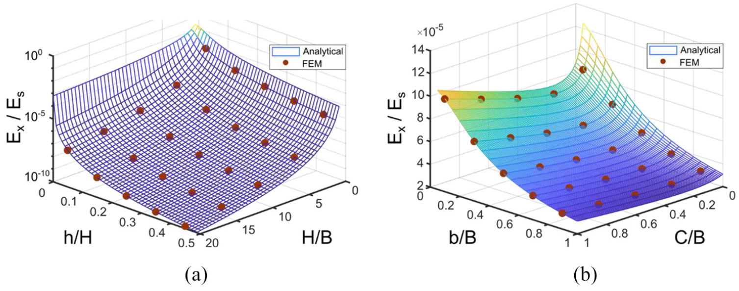
Variation of effective elasticity modulus in x-direction for a Fish Cell metamaterial with t = 0.01B and W = B with respect to (a) aspect ratio of the cell and vertical component of inclined rib’s length for C = 0.1B and b = 0.5B, (b) connector’s length and horizontal component of rib’s length for H = B and h = 0.25H.
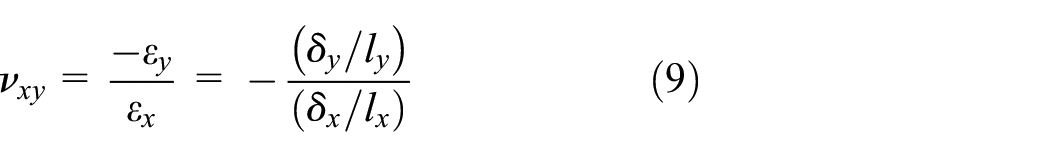
2.1.2. Poisson’s ratio νxy
Poisson’s ratio is derived using equation (9) where displacement in the x-direction, δx, is offered by equation (7). Length of the cell in the y-direction, ly, is equal to the height H. Displacement in the y-direction, δy, at point “B” is obtained by derivation of total energy with respect to P1 as

Substituting
2.2. Loading in the y-direction
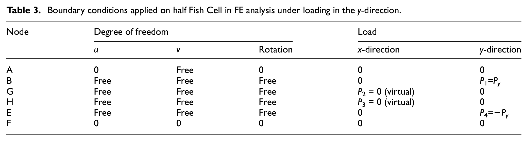
Similar to loading in the x-direction and considering the deformation mechanism of the cell in a tessellation, loading in the y-direction is studied. The deformed shape of the Fish Cell tessellation is shown in Figure 4(a). The main deformation in the unit cell under loading in the y-direction is bending of the inclined members as understood from the tessellation. Extension in y-direction causes the convex section of the cell to contract, while the concave section expands with the same value along the x-direction. The magnified view of the Fish Cell in Figure 4(a) indicates the symmetry of the deformed shape about the cell axis. Moreover, deformations in the Fish Cell and the adjacent rotated cell are the same. As a result, half Fish Cell as shown in Figure 4(b) represents the unit cell deformation to derive the equivalent elastic modulus in the y-direction, Ey. Applying the symmetry conditions, displacement in x-direction and rotation are constrained at node “F” and the corresponding reaction load R and moment M1 are considered at point “A.” Displacement in the y-direction at point “F” is also constrained to prevent rigid body motion, which results in the clamp boundary condition. Since load transfer from one cell to another happens through inclined members, loads P1 and P4 that are equal to Py are applied with opposite directions at nodes “B” and “E,” respectively. Loads P2 and P3 are virtual loads since nodes “G” and “H” have the same but opposite displacements in the x-direction. When two Fish Cells are attached by rotation to form the unit cell, node “G” of one cell will be connected to the node “H” of the other via connectors. Because of the same displacement and no rotation at nodes “G” and “H,” connectors will experience neither tension/compression nor moment. Similar to section 2.1, the FE analysis is performed on a half-cell to confirm the validity of the boundary conditions employed. The boundary conditions in FE analysis for the half Fish Cell shown in Figure 4(b) are presented in Table 3. The deformed shape of the half Fish Cell under described loading is shown in Figure 4(c) that is compliant with the deformed shape of the cell in tessellation.
(a) Deformed shape of the Fish Cell in a tessellation under loading along the y-direction, (b) free body diagram of half Fish Cell, and (c) deformed shape of the half Fish Cell obtained from FE analysis.
Boundary conditions applied on half Fish Cell in FE analysis under loading in the y-direction.
Starting from node “A,” the bending moment of each member is written in equation (B-1) in Supplemental Appendix B. Similarly, the axial force at each member is derived as in equation (B-2). Using forces and moments at each member, the total strain energy is obtained using equation (B-3) where bending and stretching of the members are considered. Loading and boundary conditions in Table 3 are considered to model the half Fish Cell deformation. Since there is no bending moment applied on nodes “G” and “H,” members “CG” and “DH” are neglected in bending strain energy derivation. Displacement in the x-direction and rotation of the point “A” are zero due to symmetry along the Fish Cell axis. This means that total strain energy derivative with respect to the corresponding reaction load and moment at point “A” is zero as in equations (B-4) and (B-5) in Supplemental Appendix B. Hence, relations for reaction load R and moment M1 are derived as in equations (B-6) and (B-8).
2.2.1. Equivalent elastic modulus
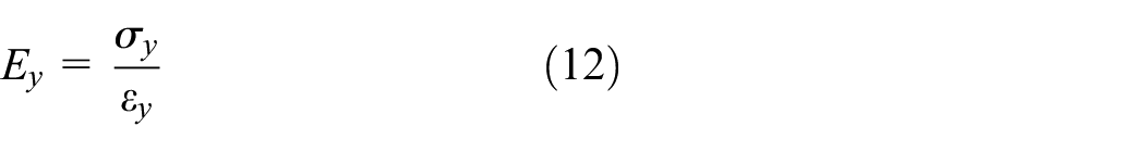
Using Hooke’s law, the equivalent elastic modulus of the homogenized Fish Cell metamaterial in the y-direction is obtained by the ratio of stress to strain as
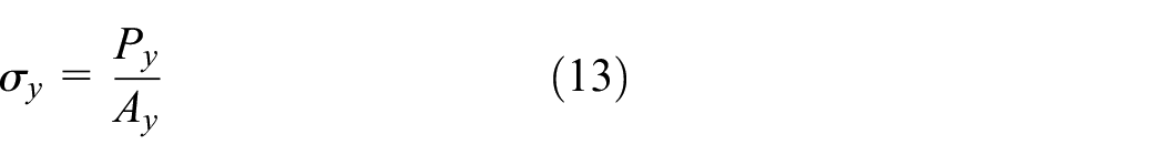
The stress σy is equal to the total force in y-direction divided by the effective area Ay=W(B+C)
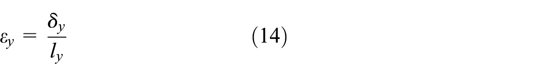
The strain εy is equal to the displacement in y-direction divided by the effective length ly=H
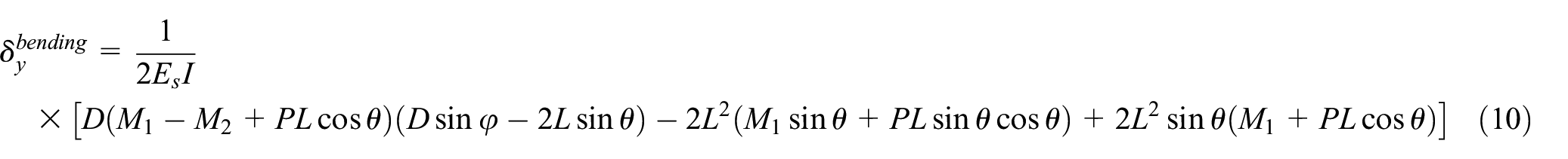
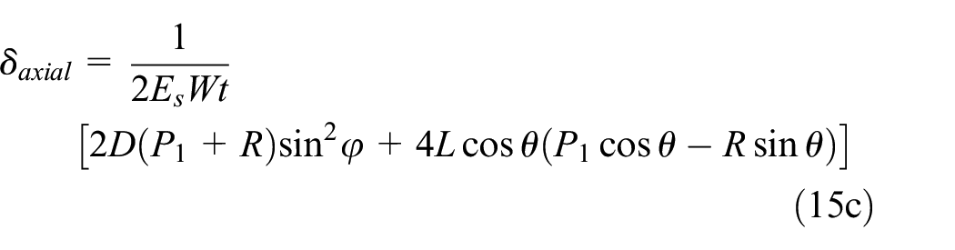
Displacement δy is obtained by calculating strain energy and applying Castigliano’s theorem to the load P1, as indicated in Supplemental Appendix B

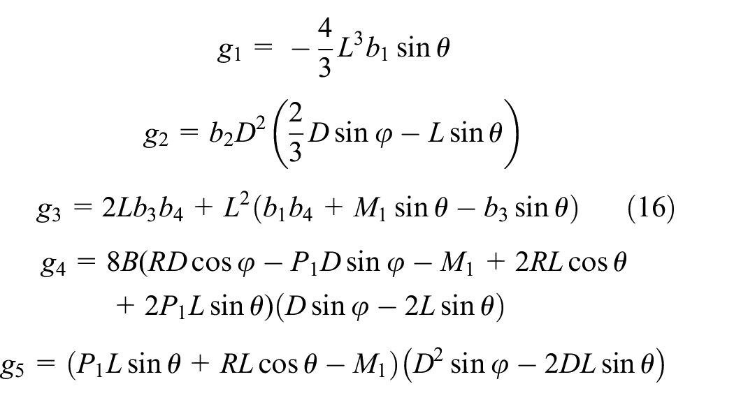
The coefficients gi (i = 1:5) are described in equation (16) where reaction load R, moment M1, and coefficients bi are described in Supplemental Appendix B
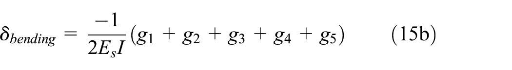
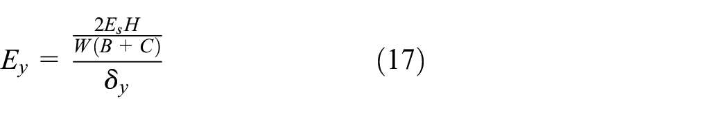
Combining equations (12) to (15) leads to the closed form solution for equivalent elastic modulus in the y-direction as obtained in equation (17). It is evident that equivalent modulus relation is independent of load Py because the load term in σy is omitted by the load term in δy
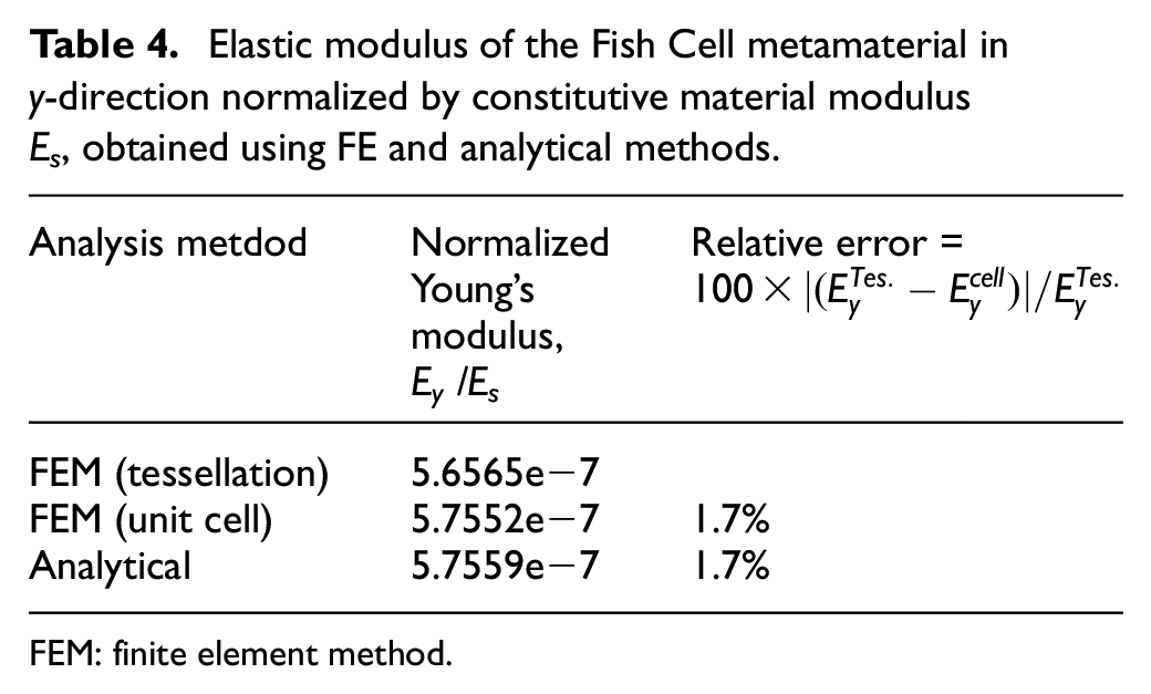
The elastic modulus of the Fish Cell with material and geometrical parameters mentioned in section 2.1 is obtained using FE analysis and equation (17). The results from the analytical method and finite element method (FEM) are compared in Table 4 where FE results are developed for both unit cell and tessellation. Because the base members are shared between two cells, half of bending stiffness is considered for each base. As a result, elastic modulus from the analytical method is verified with FE results for the tessellation with 1.7% relative error.
Elastic modulus of the Fish Cell metamaterial in y-direction normalized by constitutive material modulus Es, obtained using FE and analytical methods.
FEM: finite element method.
Effect of Fish Cell geometrical parameters on the elastic modulus in the y-direction is shown in Figure 5 where further validation of the trend using FE analysis is also provided. The diagrams show that elastic modulus is highly sensitive to variations of b where values decline up to three orders of magnitude by increasing b, while the other three parameters vary in the same order of magnitude. This is due to the moment arm of the loading in the y-direction which is length b. Increasing the connector’s length also results in elastic modulus reduction as shown in Figure 5(b). Variation of elastic modulus with vertical component of rib’s length is negligible for small aspect ratios, while a declining trend is seen at large aspect ratios as shown in Figure 5(a). Elastic modulus increases by increasing the aspect ratio for constant b/B and C/B ratios.
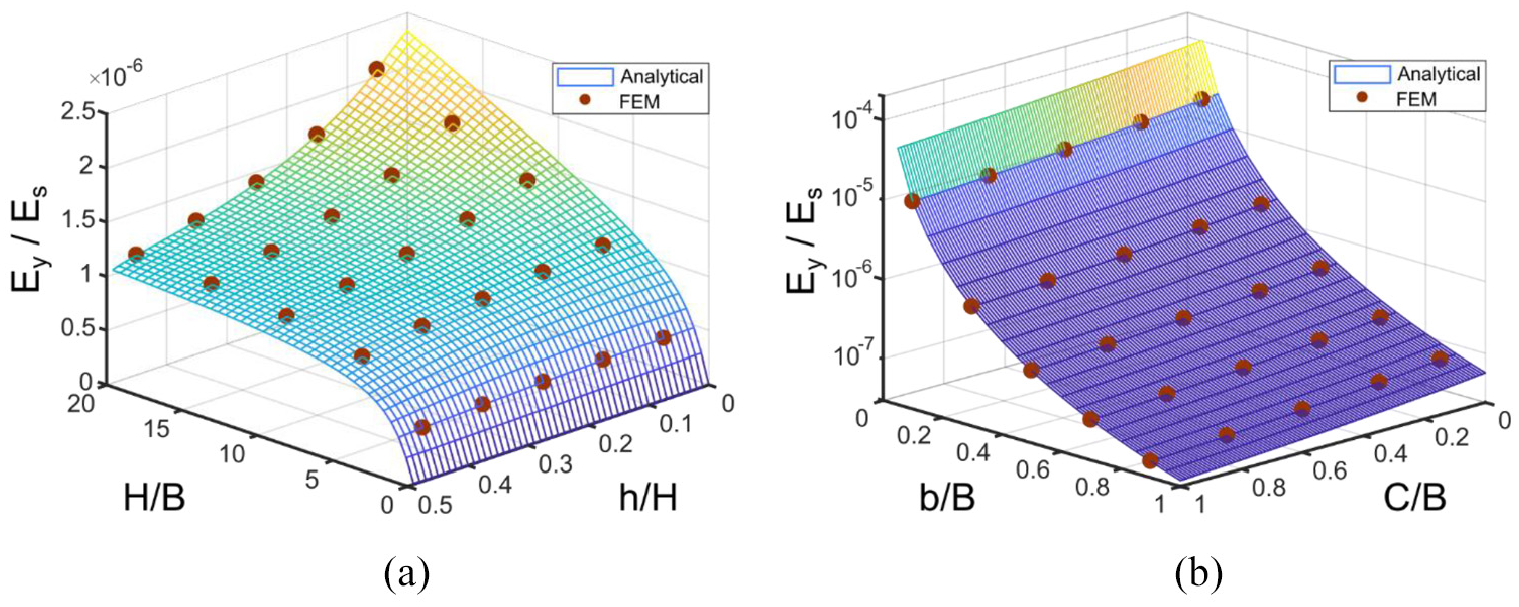
Variation of effective elasticity modulus in y-direction for a Fish Cell metamaterial with t = 0.01B and W = B with respect to (a) aspect ratio of the cell and vertical component of inclined rib’s length for C = 0.1B and b = 0.5B and (b) connector’s length and horizontal component of rib’s length for H = B and h = 0.25H.
2.2.2. Poisson’s ratio νyx
Poisson’s ratio νyx can be proved mathematically equal to zero; however, for the sake of brevity and length of the paper, the formulation is not presented. The detailed justification of zero νyx is discussed in Part I of this article. Deformations at nodes “C” and “D” are equal but in the opposite directions, which are followed by nodes “G” and “H.” When two cells are attached by rotation, nodes “G” and “H” meet each other. Because of the same displacement, no load will be exerted on the connectors, which means no force in the x-direction is transferred from one cell to another. Since bending deformation of the inclined ribs occurs inside the cell domain and no lateral loads exist to cause lateral deformation, Poisson’s ratio νyx is zero.
2.3. Loading in the z-direction
Considering Hooke’s law, the ratio of the stiffness of cellular material to the stiffness of bulk solid material can be obtained for the same cross-section area. For a solid material with a cross-section area of As, stiffness can be obtained as
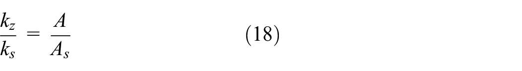
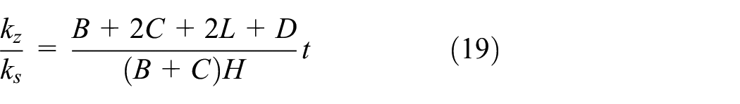
where A is the load bearing area of the unit cell and is equal to the total length of members times thickness. The total area of the unit cell domain that is the same as bulk material is As= (B+C)H. The stiffness ratio in the z-direction for Fish Cell is obtained using equation (19)
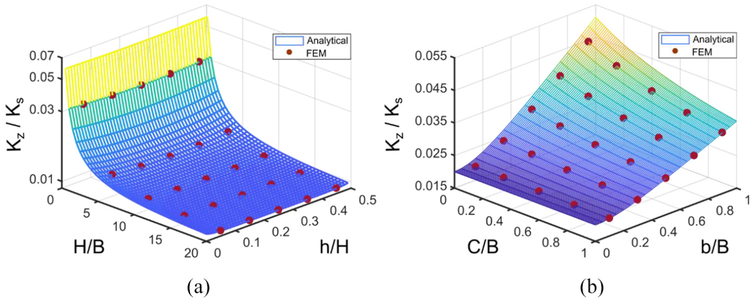
The validity of the equation (19) is investigated using FE analysis where the tensile load has been applied to the unit cell as shown in Figure 6 and dimensions of the cell as mentioned in section 2.1 are considered. To conduct FE analysis, displacement in the z-direction on the bottom surface is constrained and on the top surface, uniform displacement in the z-direction is applied while other degrees of freedom are free. Only at one point at the bottom surface, all degrees of freedom are closed to prevent the rigid body motion. FE analysis is performed using two models: shell with S8R elements and solid with C3D20 elements where fine mesh in both cases is applied for great accuracy. The results of the two FE models are compliant with each other and are also verified by the value obtained for tessellation as shown in Table 5. It should be noted that under real tensile or compression test, all degrees of freedom on the top and bottom surface will be constrained. However, this causes a large error with respect to results from equation (19) because the effect of boundary conditions and lateral displacement of the members due to the Poisson’s ratio are not considered in equation (19). The relative error of the analytical model in Table 5 is calculated with respect to the tessellation value.
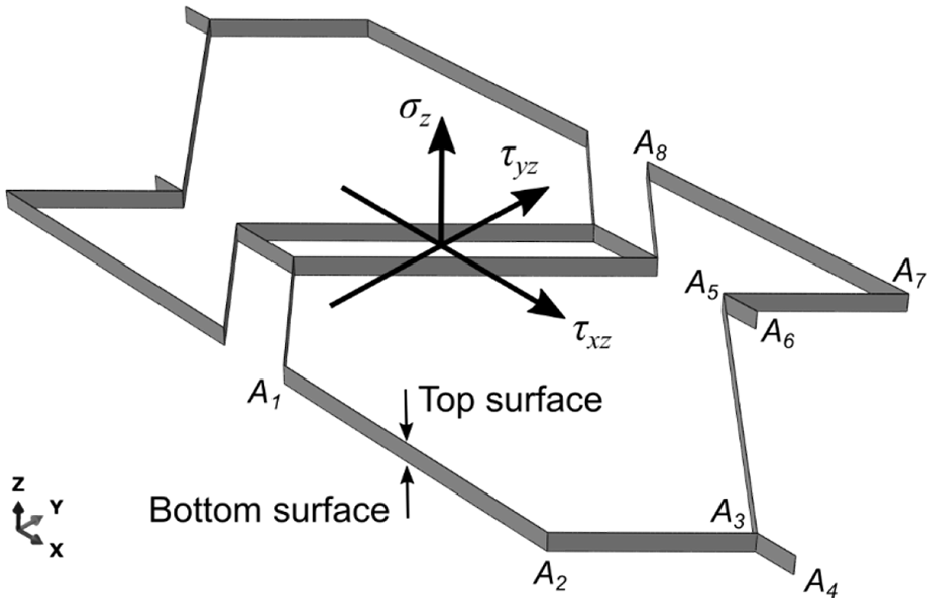
Loading and boundary conditions imposed on the unit cell to measure stiffness in the z-direction.
Elastic modulus of the Fish Cell metamaterial in z-direction normalized by constitutive material modulus Es, obtained using FE and analytical methods.
FEM: finite element method.
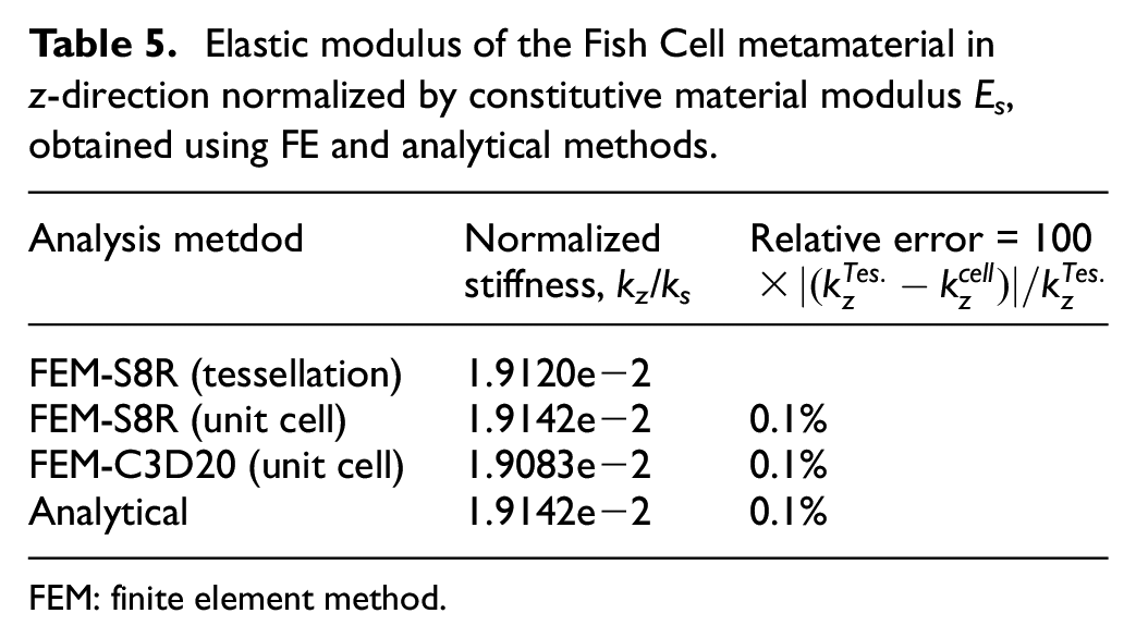
A parametric study is conducted for out of plane stiffness kz as shown in Figure 7. The trend of stiffness variation with geometric parameters is also verified using FE analysis to further validate equation (19). It is found from Figure 7 that aspect ratio H/B and the horizontal component of the rib’s length b have a larger effect on stiffness in the z-direction. Variation of stiffness with respect to the vertical component of rib’s length h is negligible. At small b/B values, connector’s length variation does not affect the stiffness value, while at b/B close to unity, stiffness reduces when the connector’s length increases.
Variation of effective elastic modulus in z-direction for a Fish Cell metamaterial with t = 0.01B and W = B with respect to (a) aspect ratio of the cell and vertical component of inclined rib’s length for C = 0.1B and b = 0.5B and (b) connector’s length and horizontal component of rib’s length for H = B and h = 0.25H. The red circles indicate the values obtained from FE analysis using ABAQUS.
3. Shear loading
3.1. In-plane shear Gxy
Pure shear loading is considered for shear analysis where the loading and boundary conditions on the tessellation are shown in Figure 8(a). The magnified view of the unit cell in tessellation shows that main deformation under pure shear loading is bending of the base members. For pure shear loading, same shear stress τxy = τyx = τ has been applied to the edges of the tessellation by exerting concentrated forces on the corresponding nodes of each edge. The sum of these concentrated forces divided by the area of the edge is equal to the shear stress. Displacements of one node at the corner of tessellation are constrained in x- and y-direction to prevent the rigid body motion.
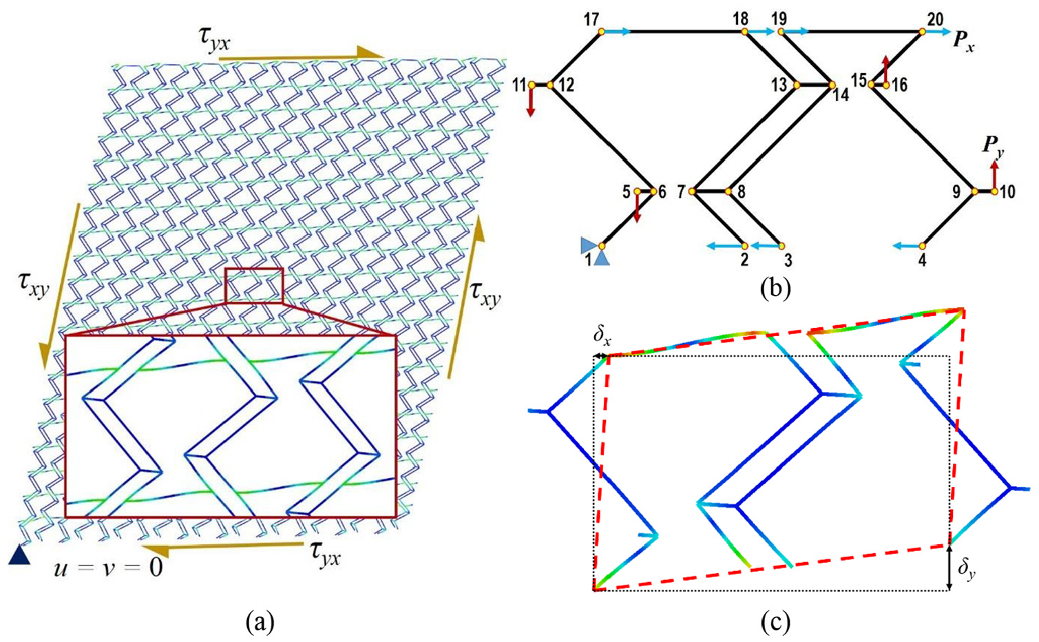
(a) Deformation of the tessellation under pure shear loading with a magnified view of the unit cell, (b) schematic of the unit cell with loads and boundary conditions for pure shear analysis, and (c) deformed shape of the unit cell under pure shear.
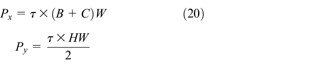
For the unit cell, one full thickness base member is used as shown in Figure 8(b). Similar to the tessellation, stress on the edges of the unit cell has been applied as concentrated loads Px and Py on the corresponding nodes of each edge where Px and Py are defined in equation (20). Loads and boundary conditions imposed on the corresponding nodes of the unit cell are defined in Table 6. The deformed shape of the unit cell under described loading is shown in Figure 8(c) where dotted rectangle shows the unit cell domain before shear deformation and dashed parallelogram shows the domain after pure shear loading
Boundary conditions and concentrated loads imposed on the unit cell for pure shear analysis.
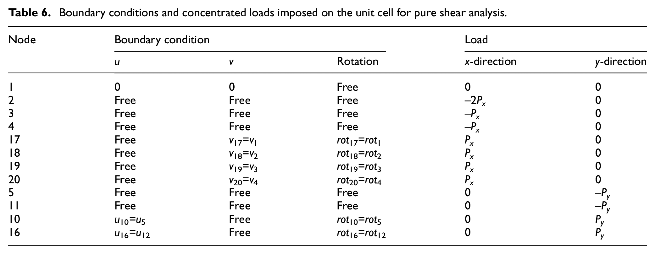
The most important parameter affecting the shear response and deformation is the boundary conditions. In order to obtain deformation for a unit cell, similar to that shown in the magnified view in Figure 8(a), PBCs must be applied. The only reason homogeneous boundary conditions on node 1 was applied is to prevent rigid body motion. Xia et al. (2003, 2006) presented an explicit unified form of boundary conditions for a periodic RVE that satisfies periodicity conditions and satisfies any combination of multiaxial loads. They also showed that homogeneous boundary conditions on a periodic unit cell can be valid only when normal tractions are applied on boundaries. Therefore, homogeneous boundary conditions used for deriving Ex and Ey in this article are valid but cannot be expanded to the shear loading. Because the assumption that planes remain plane after deformation is not valid anymore and also violates stress and strain periodicity conditions, homogeneous boundary conditions cannot be used in the shear analysis. Hence, PBCs are considered for shear loading to meet periodicity requirements, which means the boundaries of the unit cell after deformation must exactly meet each other without overlap or separation. In this regard, PBCs for the unit cell are presented in Table 6. These conditions engage the degrees of freedom of the corresponding nodes on two opposite edges with each other.
In order to perform parametric study and obtain equivalent shear modulus for a range of geometrical parameters, the unit cell FE analysis code was written in MATLAB. Bending and axial deformations were considered for each member and cubic shape function was used where each member was assigned one element. In order to solve the multi-constraint problem in MATLAB, master-slave method (MSM) was used (Felippa, 2004) which allows solving models with multi-point constraints and PBC. In order to derive the equivalent shear modulus of the unit cell, the displacements δx and δy as shown in Figure 8(c) were measured to calculate the shear strain as in equation (21). Substituting shear strain in Hooke’s law as in equation (22), the effective shear modulus was obtained.
PBCs can be applied in ABAQUS between two nodes as MPCs by writing a subroutine that allows defining a relation between desired degrees of freedom as in Table 6. The shear modulus obtained from two FE models with material and dimensions mentioned in section 2.1 is presented in Table 7 for the unit cell and tessellation. The relative errors of the unit cell shear modulus are calculated with respect to the tessellation
Comparing the in-plane equivalent shear modulus of the Fish Cell metamaterial normalized by constitutive material modulus Es using two FE models.
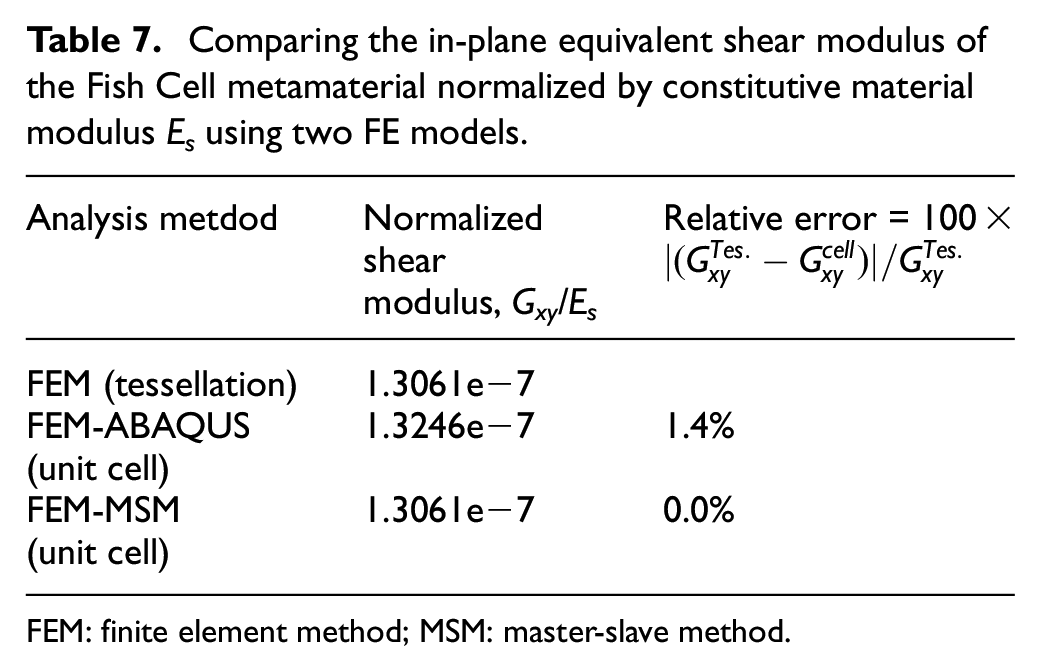
FEM: finite element method; MSM: master-slave method.
Parametric study on the shear modulus is conducted using equation (22) and the results are presented in Figure 9. It is evident that effective shear modulus of the Fish Cell metamaterial is highly dependent on the aspect ratio of the unit cell. Shear modulus reduces by several orders of magnitude when aspect ratio increases. For a constant height H, the shear modulus reduces by reducing the base members’ length. By increasing the aspect ratio, variations of shear modulus with the vertical component of rib’s length also increase as shown in Figure 9(a). Variations of shear modulus with connector’s length and the horizontal component of rib’s length are from the same order of magnitude as shown in Figure 9(b). Shear modulus increases generally by increasing the connector’s length and has a maximum before C/B reaches unity. Generally, for most of the b/B domain, shear modulus reduces by increasing the horizontal component of the rib’s length.
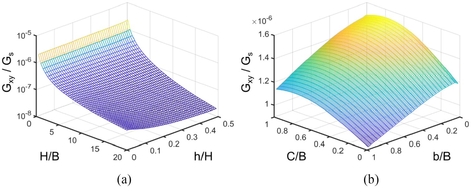
Variation of the in-plane shear modulus with respect to (a) aspect ratio of the cell and vertical component of inclined rib’s length for C = 0.1B and b = 0.5B and (b) connector’s length and horizontal component of rib’s length for H = B and h = 0.25H.
3.2. Out of plane shear
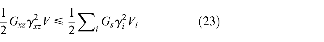
The Fish Cell transverse shear stiffness is important to study when the structure sustains shear loads such as torsion on the wing skin. The equivalent transverse shear modulus of the honeycomb structures is studied using unit load and displacement method (Kelsey et al., 1958) that leads to an upper and lower boundary for the effective transverse shear modulus. These lower(Reuss) and upper(Voigt) bounds are used to evaluate the transverse shear modulus of several 2D cellular structures (Hohe and Becker, 2002) because the accurate values can be obtained only using numerical models due to complex deformations and stress distribution (Gibson and Ashby, 1999; Malek and Gibson, 2015). Therefore, equivalent transverse shear modulus of the Fish Cell metamaterial in two directions is presented by the lower and the upper bounds. The lower bound is obtained from strain energy equation by considering a strain distribution on the unit cell and the upper bound is derived from complementary energy by applying an admissible stress distribution. The unit cell in 3D format and coordinate system are shown in Figure 6 where bottom and top surfaces are also annotated. Considering the upper bound for shear modulus Gxz, the uniform strain γxz is applied on the unit cell. The equilibrium states that the strain energy of a structure with equivalent shear modulus is equal or smaller than the sum of the strain energy of each member as defined by equation (23), where Gs is the solid material’s shear modulus
The contribution of each member to the strain energy is calculated using the shear strain and the volume of each member presented in equations (24) and (25), respectively. The notation of the members is presented in Figure 6
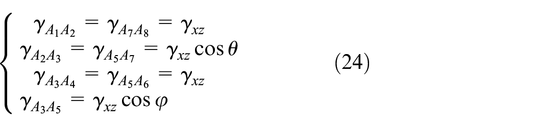
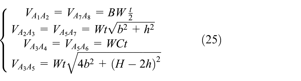
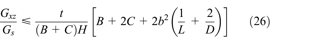
Substituting equations (24) and (25) in equation (23) and using the definition of the L and D presented in section 2.1 and equation (3), the closed form relation for the upper bound of the Gxz is obtained as in equation (26).
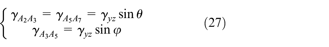
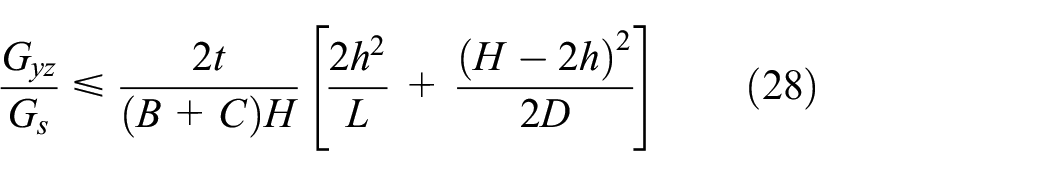
Similarly, by considering the shear strains of the members presented in equation (27) for the orthogonal direction, the upper bound of the equivalent shear modulus Gyz is obtained as in equation (28). It must be noted that under transverse shear loading in the y-direction, the base and connector members (A1A2, A3A4, A5A6, and A7A8) do not sustain any shear load due to bending which has negligible contribution to the overall shear stiffness; therefore, their shear strain is neglected
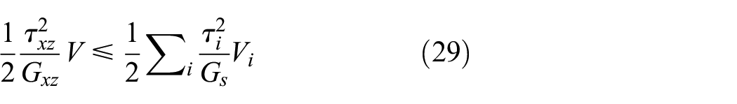
The lower bound of the equivalent transverse shear modulus is obtained from the complementary energy as presented in equation (29)
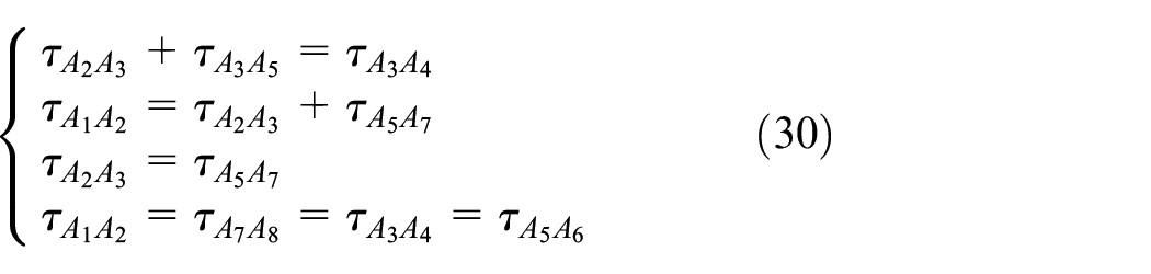
The base and connectors of the Fish Cell have equal stress and according to the equilibrium in the z-direction at the joints, the stresses in the members are defined as in equation (30)
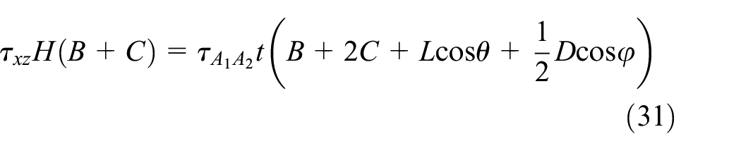
The stress values are derived by writing the equilibrium of loads in the x-direction
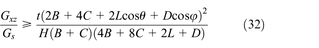
Substituting the stresses and volumes of the members in equation (29), the lower bound is derived as
Under shear stress in the y-direction, the base and connectors do not sustain any shear stress and are neglected. According to the equilibrium of the shear stress in the z-direction at joints, the shear stress in inclined ribs are equal; that is,

Similarly, the lower bound of the transverse shear modulus Gyz is obtained from the equilibrium of the complementary energy
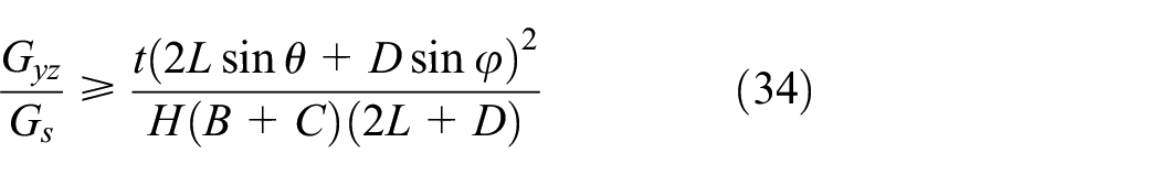
Due to the complexity of the stress distribution in transverse shear loading, the FE models are also developed using ABAQUS with quadratic shell elements S8R and fine mesh size to study the equivalent transverse shear modulus. The results of FE analysis are dependent on the boundary conditions imposed on the unit cell. The translational boundary conditions considered for Fish Cell metamaterial are ux = uy = uz = 0 at the bottom surface. At the top surface (Lira et al., 2009), uy = uz = 0 and ux = γxz×W for shear loading in the x-direction, while ux = uz = 0 and uy = γyz×W for shear loading in the y-direction, where γxz = γyz=0.01. The rotational degrees of freedom are rotx = rotz = 0 for shear loading in the x-direction and roty = rotz = 0 for shear loading in the y-direction on both surfaces (Lira and Scarpa, 2010). The effective stress is then calculated by dividing the sum of reaction forces on a face to the effective area of the unit cell. The normalized transverse shear modulus obtained from FE analysis are compared to the upper and lower bounds in both directions in Table 8. The difference of the shear modulus obtained from a unit cell and a tessellation is negligible as shown in Table 8; therefore, the parametric studies are verified with FE models of a unit cell.
Transverse shear modulus Gxz and Gyz obtained for a unit cell with B = 8 mm, W = 1 mm, t = 0.1 mm, b = h = 6 mm, and H = 24 mm; Gs = Es/(2(1 +ν)) is the shear modulus of the solid material.
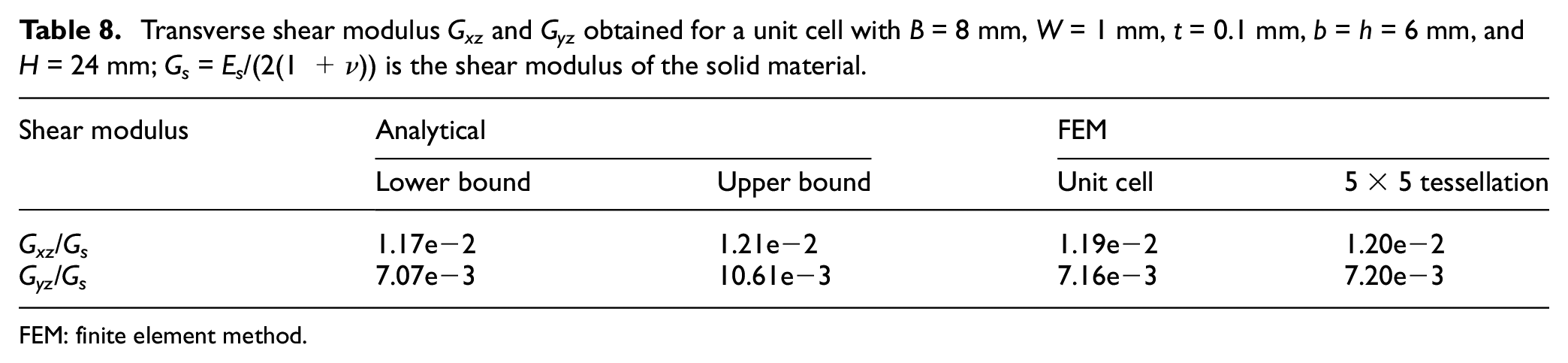
FEM: finite element method.
The deformed Fish Cell under shear loading in the x- and y-direction are presented in Figure 10(a) and (b), respectively. Figure 10(b) verifies the assumption of negligible contribution of the base and connectors to the shear modulus Gyz as the stress levels are close to zero comparing to the inclined ribs. The effect of changing aspect ratio H/B on the shear modulus Gxz is strong as shown in Figure 10(c) where the normalized modulus reduces orders of magnitude by increasing the aspect ratio. In the other direction, Gyz changes at small aspect ratios, while the vertical component of rib’s length, h, has no significant effect on neither Gxz nor Gyz. Figure 10(d) and (f) shows that shear modulus Gyz obtained from FE is closer to the lower bound.
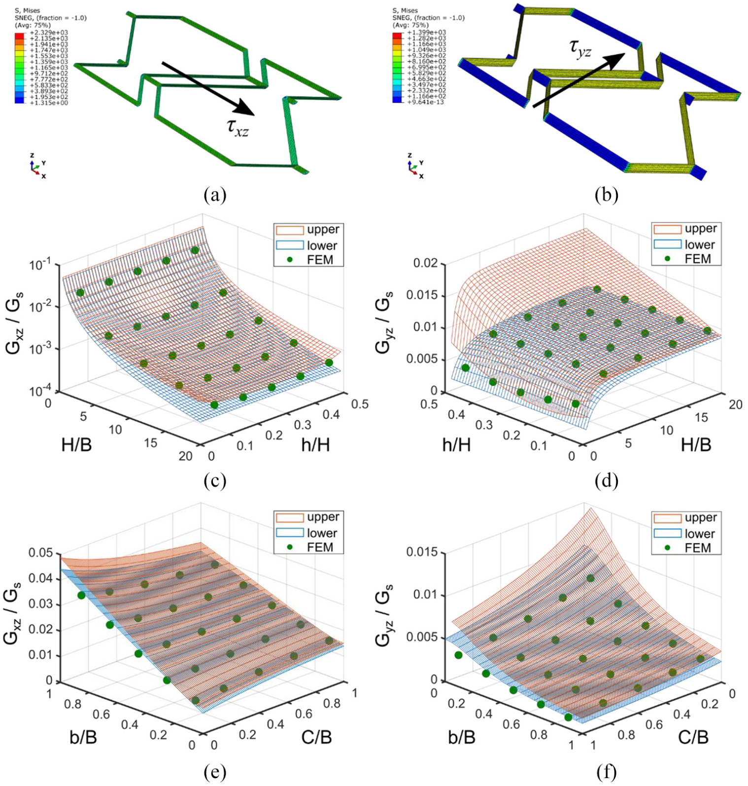
Deformed shape and stress distribution in Fish Cell metamaterial under shear loading (a) τxz and (b) τyz. Effect of the aspect ratio H/B and the vertical component of the rib’s length, h, on the shear modulus (c) Gxz and (d) Gyz where C = 0.1B and b = 0.5B. Effect of the connector’s length and horizontal components of the rib’s length, b, on the shear modulus (e) Gxz and (f) Gyz where H = B and h = 0.25H. For all cases, B = 10 mm, W = B, and t = 0.01B.
4. Discussion
In section 2, it was shown that Fish Cell’s ZPR is independent of the parameters’ value and originates from the cell topology. Therefore, an optimized range of parameters based on desired equivalent elastic properties can be obtained for Fish Cell. In addition to optimization of the parameters’ values, the topology can also be subject of optimization by considering geometrical requirements. Members BC, CD, and DE have pointwise symmetry with respect to the midpoint of member CD as shown in Figure 2(b). This geometrical relation is the basis of the Fish Cell topology that results in ZPR. Saving the pointwise symmetry of the inclined members, other geometries can be also applied for the inclined section to optimize the elastic properties of the Fish Cell. The Fish Cell analyzed in sections 2 and 3 was based on the combination of two convex and concave hexagons by the omission of the mutual base as discussed in the companion paper. In addition to the hexagon, higher order regular polygons with even number such as octagon can be also used as shown in Figure 11(a). The FE analysis of the octagonal Fish Cell tessellation is performed using ABAQUS in two orthogonal directions with beam elements B22 and fine mesh where ZPR in both directions is proved. Analytical curves such as spline that provide better control on the inclined member’s profile design can be also used and result in ZPR as shown in Figure 11(b). This flexibility of the Fish Cell topology provides opportunities for future optimization studies.
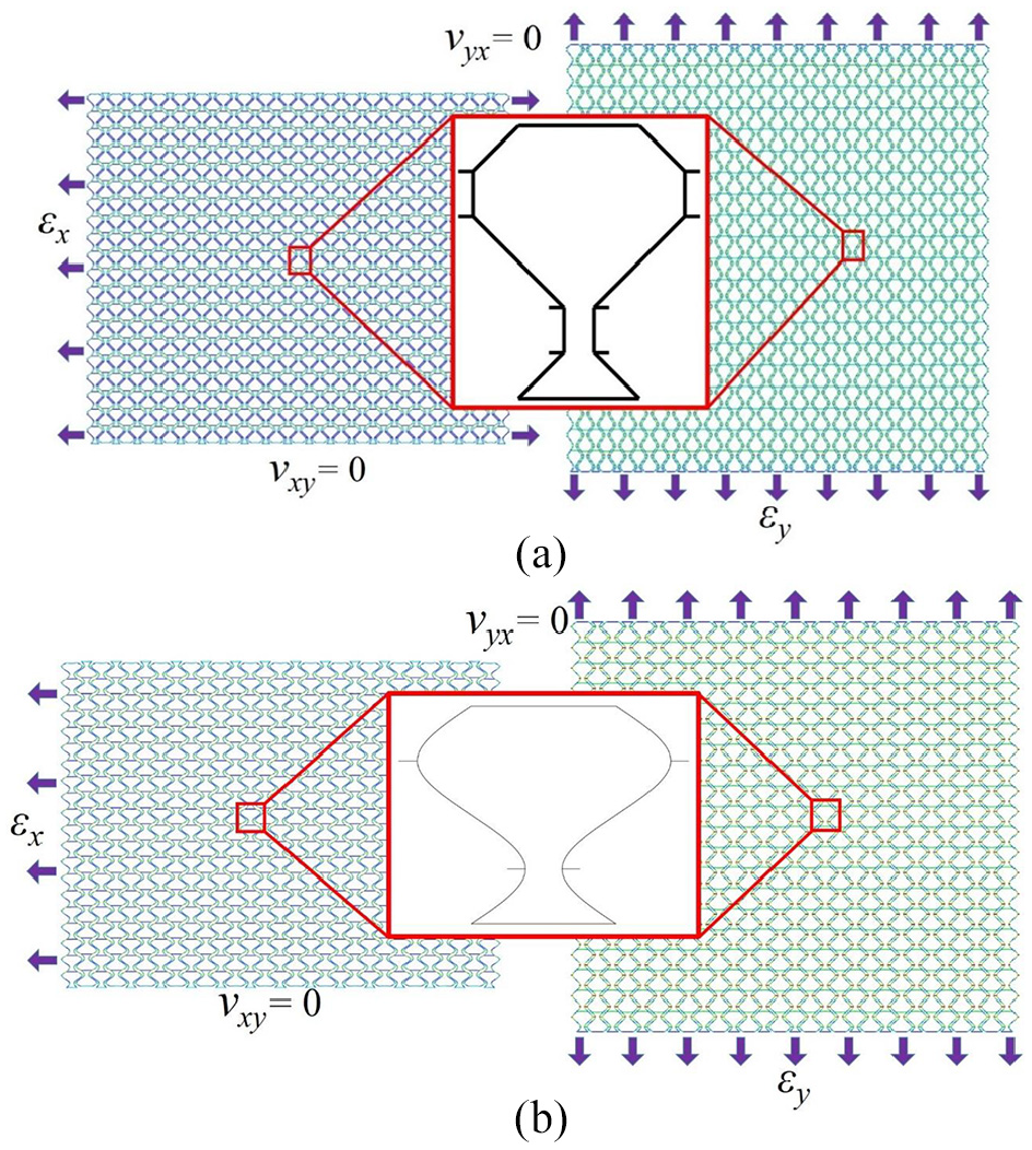
Different topologies for Fish Cell inclined section with ZPR: (a) octagonal polygon and (b) spline curve.
5. Conclusion
Fish Cell as a new ZPR metamaterial is presented and its elastic properties are investigated. The equivalent elastic properties of the Fish Cell are obtained and verified using analytical and numerical models. The study shows that Fish Cell geometry achieves ZPR in both in-plane directions for any arbitrary value of its geometrical parameters. Equivalent elastic modulus in planar directions and equivalent stiffness in the transverse direction are derived. Importance of PBCs in the shear analysis is shown and equivalent shear modulus is obtained by considering proper PBC in the pure shear loading to obtain the same deformation in the unit cell as in the tessellation. The transverse shear modulus is studied based on Reuss and Voigt bounds and verified with FE analysis where results are closer to the lower bound. The elastic properties analysis is followed by parametric studies where the effect of aspect ratio, horizontal and vertical components of the inclined rib’s length, and connector’s length are studied. The results show that aspect ratio of the Fish Cell, H/B, has a strong effect on the transverse elastic properties. Results suggest that based on design requirements, an optimum range of geometrical parameters can be obtained using optimization methods. Based on the relations obtained in this article, optimization of the Fish Cell metamaterial for morphing skin’s core or other applications can be conducted in future studies.
Supplemental Material
appendix – Supplemental material for Fish Cells, a new zero Poisson’s ratio metamaterial—part II: Elastic properties
Supplemental material, appendix for Fish Cells, a new zero Poisson’s ratio metamaterial—part II: Elastic properties by Mohammad Naghavi Zadeh, Iman Dayyani and Mehdi Yasaee in Journal of Intelligent Material Systems and Structures
Footnotes
Declaration of conflicting interests
The author(s) declared no potential conflicts of interest with respect to the research, authorship, and/or publication of this article.
Funding
The author(s) received no financial support for the research, authorship, and/or publication of this article.
Supplemental material
Supplemental material for this article is available online.
References
Supplementary Material
Please find the following supplemental material available below.
For Open Access articles published under a Creative Commons License, all supplemental material carries the same license as the article it is associated with.
For non-Open Access articles published, all supplemental material carries a non-exclusive license, and permission requests for re-use of supplemental material or any part of supplemental material shall be sent directly to the copyright owner as specified in the copyright notice associated with the article.