
Abstract
A novel cellular mechanical metamaterial called Fish Cells that exhibits zero Poisson’s ratio in both orthogonal in-plane directions is proposed. Homogenization study on the Fish Cells tessellation is conducted and substantially zero Poisson’s ratio behavior in a homogenized tessellation is shown by numerical analysis. Experimental investigations are performed to validate the zero Poisson’s ratio feature of the metamaterial and obtain force–displacement response of the metamaterial in elastic and plastic zone. A detailed discussion about the effect of the numerical model approach and joints on the structural response of the metamaterial is presented. Morphing skin is a potential application for Fish Cells metamaterial because of the integration benefits of zero Poisson’s ratio design. The structural integrity of the Fish Cells is investigated by studying the stiffness augmentation under tension and in presence of constraints on transverse edges. Finally, geometrical enhancements for improved integrity of the Fish Cells are presented that result in substantially zero stiffness augmentation required for morphing skins.
1. Introduction
Metamaterials refer to materials designed in micro-/nanoscale to expose exotic behavior in the macroscale. Mechanical metamaterials can tune mechanical properties such as elastic modulus, bulk modulus, Poisson’s ratio, coefficient of thermal expansion, and dynamic response of the structure. The smallest fundamental representative volume element or unit cell of the metamaterial is designed with a specific geometry or resonant behavior to be repeated periodically in two dimension (2D) or three dimension (3D) and create large-scale structures with the desired tuned property (Bertoldi et al., 2017). Recent advances in additive manufacturing have enabled the fabrication of structures with arbitrarily complex micro-architecture that has attracted increasing attention to the development of mechanical metamaterials (Chen and Zheng, 2018; Jiang and Wang, 2016; Vyatskikh et al., 2018; Zheng et al., 2014).
Mechanical metamaterials with tuned Poisson’s ratio can possess negative or zero values (Clausen et al., 2015). According to the mathematical definition, zero Poisson’s ratio (ZPR) metamaterials expose neither transverse displacements under in-plane longitudinal loadings nor double curvature under out of plane bending moments, because there is no coupling between stresses and strains in two orthogonal directions (Grima et al., 2010). Therefore, ZPR metamaterials present single curvature under bending (unclastic) comparing to the anticlastic curvature of positive Poisson’s ratio (PPR) and synclastic curvature of the negative Poisson’s ratio (Sanami et al., 2014). These unique characteristics are attractive in many applications: in tissue engineering, ZPR scaffolds have similar function as natural tissue providing better wound healing and tissue regrowth (Soman et al., 2012); in amorphous materials like viscous thin films, ZPR materials can be tightly rolled to make soft ultrathin coatings without thickness modification requirements or squeezing force increment (Nguyen et al., 2012); and in textile industries where ZPR weaving patterns for fabrics can be developed (Zulifqar et al., 2018). ZPR metamaterials presented in the literature can be classified according to their compliance in a planar context, that is, how much flexibility in each direction they demonstrate.
ZPR with compliance in one direction mainly exists in designs where continuous solid strips are connected together by inclined ribs that can bend easily compared to the solid strips. The stiffness in the direction of the solid strips is much larger than normal direction where bending of the inclined ribs increases the compliance. Olympio and Gandhi (2007, 2010) proposed such a geometry, called accordion design, as a core for morphing skins as shown in Figure 1(a). Based on accordion topology, several other designs have been proposed that mostly differ in the inclined rib’s geometry such as Figure 1(b) and (c) (Bubert et al., 2010; Chen and Fu, 2018; Huang et al., 2016; Liu et al., 2013; Rong and Zhou, 2017; Zou and Zhou, 2017). Chen et al. (2015) investigated in-plane mechanical properties of three different ZPR accordion structures with hexagonal, re-entrant, and V-shaped ribs. It was shown that these three geometries with the same parameters have the same in-plane elastic modulus but different shear modulus. Although ZPR metamaterials with compliance in one direction may have large in-plane and bending stiffness along the direction of the solid strips, this can be a disadvantage since the structure will be limited to morphing in only one direction.
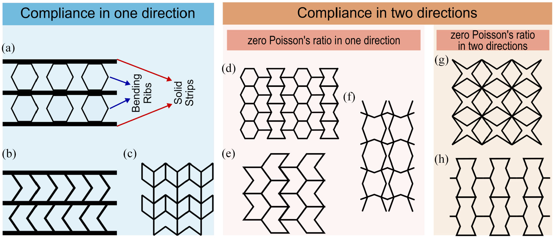
Geometrical illustration of different ZPR structures categorized according to the compliance in one and two direction. For 1D compliance in the literature, some examples are (a) accordion design with solid strips connected by bending hexagonal ligaments (Liu et al., 2013; Olympio and Gandhi, 2007, 2010), (b) ZPR structure proposed for morphing skin based on accordion topology with chevron bending ligaments (Bubert et al., 2010), and (c) modified semi re-entrant design (Chen and Fu, 2018). For 2D compliance in the literature, two categories of ZPR in one and two directions exist. For 1D ZPR in the literature, some examples are (d) hybrid honeycomb (Olympio and Gandhi, 2007, 2010), (e) semi re-entrant design (Grima et al., 2010), and (f) Silicomb (Lira et al., 2009). For 2D ZPR in the literature, some examples are (g) a star shape design by Gong et al. (2015) and (h) reverse semi re-entrant design (Wang et al., 2014).
ZPR metamaterials proposed with compliance in two in-plane directions provide the opportunity for bidirectional morphing. However, some of the designs do not have ZPR in both directions. For instance, hybrid honeycomb (Olympio and Gandhi, 2007, 2010) as shown in Figure 1(d), semi re-entrant honeycomb (Grima et al., 2010) as shown in Figure 1(e), and Silicomb (Lira et al., 2009) as shown in Figure 1(f) provide ZPR in one direction, while compliant in both directions. Solving this issue, cellular metamaterials with different geometries are proposed with designed bending deformation mechanism of the elements in the unit cell that neutralizes displacements in the orthogonal direction inside the unit cell or in connection with adjacent cells (Gong et al., 2015; Liu and Zhang, 2018; Mizzi et al., 2018; Wang et al., 2014).
ZPR behavior can be very valuable for a wide range of engineering applications such as morphing aircraft because of preventing stiffness augmentation and undesired induced curvatures. Although designs for ZPR metamaterials with compliance in two orthogonal in-plane directions are proposed with application in morphing structures (Gong et al., 2015), integration performance of the metamaterials with the morphing structure and under constraints needs to be studied further.
In this article, a new metamaterial called Fish Cells is proposed with ZPR and compliance in two directions. Experimental and numerical analysis is used to demonstrate the ZPR behavior of a homogenized tessellation. Morphing technology is considered as one application of Fish Cells ZPR metamaterial to improve the aerodynamic efficiency and performance of the aircraft (Barbarino et al., 2011). The details of integration study for morphing skin application with local constraints on lateral edges of a homogenized tessellation are conducted in section “Structural integrity for morphing application” of this article. Integration efficiency of the Fish Cells metamaterial is investigated by stiffness augmentation under tension. Finally, local geometrical enhancements for improved integrity of the Fish Cells metamaterial are presented that result in substantially zero stiffness augmentation, which is required for morphing skins applications.
2. Fish Cells metamaterial’s architecture
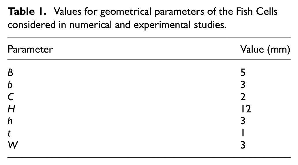
Fish Cells as a novel architecture for metamaterial is shown in Figure 2(a) where the unit cell is formed by attachment of two rotated Fish Cells that is similar to the rectangular pattern in 2D Bravais lattices. Six parameters including five parameters in the x–y plane as shown in Figure 2(b) and the out of plane thickness, W, are required to define the geometry. The five in-plane parameters are base member length B, inclined rib’s horizontal length b, inclined rib’s vertical length h, unit cell’s height H, the connector’s length C, and the uniform thickness of each member t. The out of plane thickness of the Fish Cells called W, defines the extrusion depth. The values considered for the parameters to study the Fish Cells structure are presented in Table 1.
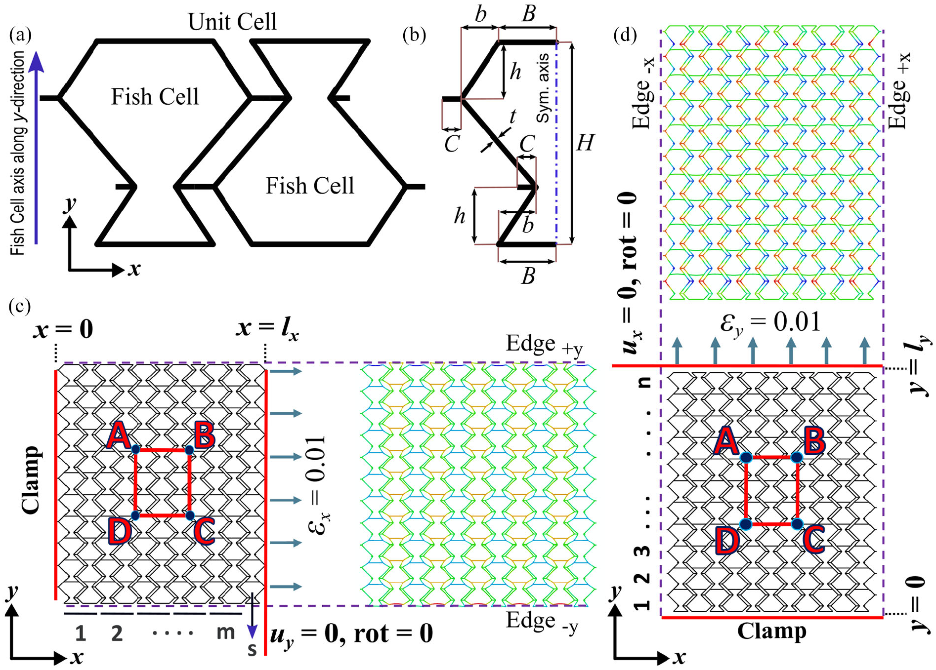
(a) Fish Cells geometry and the configuration of the rectangular unit cell is formed by connecting to rotated Fish Cells, (b) five parameters required in the x–y plane to define the Fish Cells, (c) boundary conditions and deformed shape of Fish Cells tessellation with length lx under εx = 0.01, and (d) boundary conditions and deformed shape of Fish Cells tessellation with width ly under εy = 0.01. (c) and (d) also show the method of nominating the tessellations by counting the unit cells in two directions as (m × n). The position of the Edge±x and Edge±y is shown on the tessellation, which are used in section “Structural integrity for morphing application.”
Values for geometrical parameters of the Fish Cells considered in numerical and experimental studies.
Fish Cells geometry may be considered as a modified assembly of re-entrant and hexagonal cells with negative Poisson’s ratio and PPR, respectively. Therefore, using a proper and consistent geometric ratio between re-entrant and hexagonal shapes, the Fish Cells geometry will have ZPR under loading in the x-direction, that is,
Moreover, Figure 2 highlights Edge +y and Edge−y with normal vectors in +y and −y directions as well as Edge+x and Edge−x with normal vectors in +x and −x directions. This nomination is used for studying local deformations on edges detailed in section “Structural integrity for morphing application.”
3. Concept validation
3.1. In-plane properties
Specific area ABCD at the center of the metamaterial is considered for studying ZPR behavior as shown in Figure 2. Strain in x-direction εx is defined as the ratio of length change in line AB to its initial length and εy is defined as the ratio of length change in line BC to its initial length. Poisson’s ratio is defined as the negative ratio of strain in perpendicular transverse direction to the actuation direction. To obtain ZPR, lines AD and BC should experience negligible length change and rotation when loaded in the x-direction, and similarly, for lines AB and CD when stretched in the y-direction.
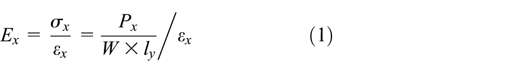
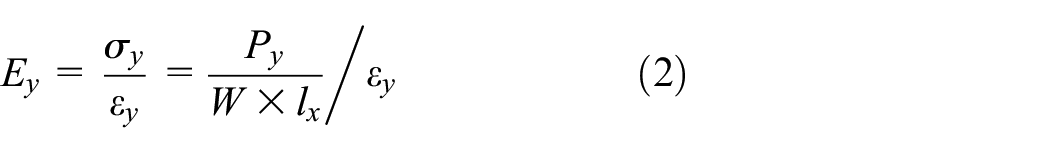
The effective elastic modulus is calculated according to equation (1) and equation (2) where P indicates the total reaction force along loading direction, and lx and ly are the length of panel in x- and y-direction, respectively
To assess the validity of ZPR design, the deformations of the metamaterial in two orthogonal directions are studied using finite element (FE) analysis.
3.2. Finite element method analysis
Investigating the response of Fish Cells metamaterial, the structure with geometric parameters presented in section “Introduction” is modeled in ABAQUS where elastic constants of Nylon PA2200, as described in section “Experimental analysis,” with E = 1130 GPa and Poisson’s ratio ν = 0.4 are used for concept analysis and integration studies. Regarding the boundary conditions, lateral edges are free, all degrees of freedom on the fixed edge are constrained, and displacement in tensile direction is allowed for the moving edge only as shown in Figure 2 for each loading direction. Nonlinear effects and strain dependency are neglected and specific displacement is imposed on moving edge according to the tessellation number to achieve a certain strain of ε = 0.01. The metamaterial structure is modeled as a 2D planar part with shear deformable quadratic beam elements B22 and a rectangular cross section with dimensions W and t. Mesh convergence studies are performed and fine mesh discretization is applied for great accuracy (i.e. less than 0.1% error margin) where the global size of 0.5 mm for each element is chosen.
3.3. Homogenization
Considering the concept of periodicity and Saint Venant’s principle (Von Mises, 1945) in the theory of elasticity, the behavior of homogenized tessellation corresponds to sufficiently large tessellations in which the effects of boundary conditions such as stress concentration are minimum (Dayyani et al., 2013). Therefore, it is important to achieve a tessellation with the right number of cells to represent a homogenized behavior. For this purpose, four structures with clamp boundary conditions at edges including the 5 × 5, 10 × 10, 15 × 15, and 20 × 20 tessellations are investigated. The previous “Finite element method analysis” section describes the simulation parameters of the models.
Figure 3(a) demonstrates the homogenization results for νxy and νyx calculated based on ABCD rectangle. Considering computation time, the results show that 20 × 20 tessellation is a good representative of a homogeneous metamaterial and substantially ZPR behavior starts from 5 × 5 tessellation. Figure 3(b) shows the convergence of results for the trend of effective elastic modulus in two directions, where the effective modulus E is normalized with respect to the original constructing material elastic modulus, Es. The elastic modulus of the metamaterial is significantly smaller than original constructing material, which is from the order of 10−3. This low stiffness ratio is useful for biomedical applications such as implants where a highly compliant structure is required in interaction with soft tissues (Engelmayr et al., 2008).
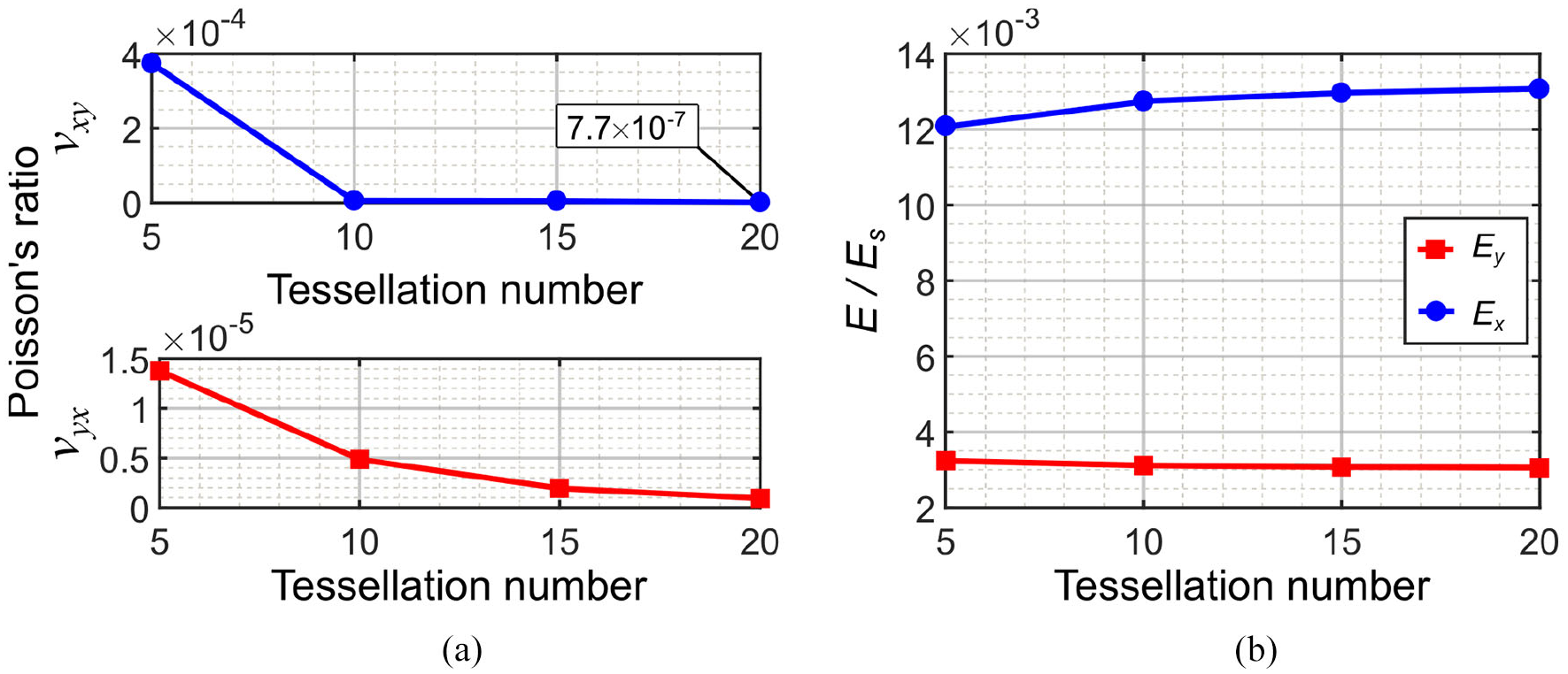
Homogenization analysis for 5 × 5, 10 × 10, and 20 × 20 tessellations: (a) Poisson’s ratio in two directions and (b) effective elastic modulus in two directions.
The values of Poisson’s ratios obtained for 20 × 20 tessellation are νxy = −7.71 × 10⁻⁷ and νyx = 9.37 × 10⁻⁷, which are small enough to be neglected. Hence, the proposed Fish Cells metamaterial has ZPR behavior in two orthogonal directions.
4. Experimental analysis
4.1. Manufacturing
Obtaining homogeneous response with minimum boundary condition effects makes manufacturing of test samples a great challenge when the size of Fish Cells should be very small comparing to the sample size. Selective laser sintering (SLS) is used for 3D printing of the metamaterials with fine tolerance (EOS P100, 3dprintuk.co.uk). The main limit in the manufacturing of Fish Cells metamaterial is the resolution of the laser for printing minimum thickness of the ribs. The minimum achievable thickness is also dependent on powder grain size for proper bonding and material homogeneity, which in this case was 56 µm on average (Nylon PA2200, EOS Gmbh). Hence, the minimum thickness of 1 mm with a manufacturing tolerance of ±0.1 mm was used.
Considering the manufacturing limitations including minimum thickness and printer desk size, Fish Cells metamaterial samples with (5 × 11) s tessellations were manufactured as shown in Figure 4(a) and (b) for νxy and νyx tests, respectively. The reason for selecting a symmetric tessellation number is maintaining the symmetry along y-direction, which is discussed more in section “Structural integrity for morphing application” of the article.
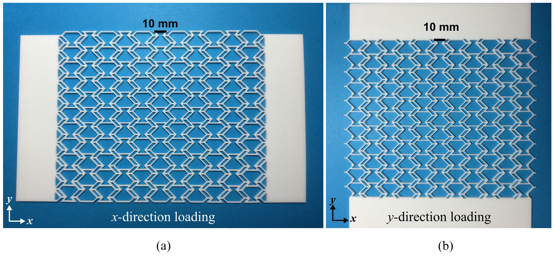
3D printed Nylon PA2200 samples for tensile tests in two orthogonal directions for the study of Poisson’s ratio: (a) νxy and (b) νyx.
4.2. Material characteristics
In addition to the Poisson’s ratio, the force–displacement response of the Fish Cells structure is also considered for investigation. Therefore, the material properties of the Nylon PA2200 as constructing material used in SLS manufacturing are investigated to supply the input data for finite element method (FEM) validation of tests. According to manufacturer datasheet, sintered parts retain the isotropic behavior. To evaluate the mechanical properties of Nylon PA2200, tensile tests are performed on five specimens using Instron 5965 machine with 5-kN load sensor. The length, width, and thickness of the specimens were 75, 14, and 3 mm, respectively. Figure 5 presents experimental stress–strain curves for five test specimens in tension. The average maximum stress reached was about 51.6 MPa, where the sample had a ductile failure at an average strain of 0.27. Poisson’s ratio is calculated from the transverse strain to axial strain ratio measured by digital image correlation (DIC) technique. The calculated average properties from tensile tests are E = 1130 MPa and ν = 0.4.
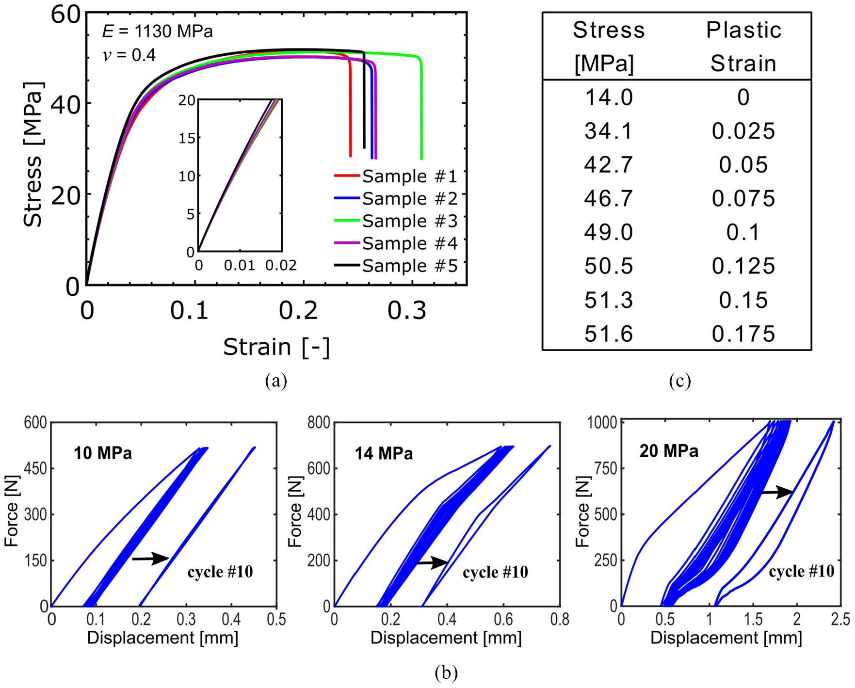
(a) Stress–strain curves of tensile test specimens made from Nylon PA2200, (b) hysteresis analysis of Nylon PA2200 under quasi-static loading for 10 cycles at different stress amplitudes to extract the proportional limit, and (c) Nylon PA2200 plastic properties extracted from tensile test results.
Although slope of the strain-stress curves changes significantly above 40 MPa, the slope is nonlinear even below 20 MPa as shown in Figure 5(a). Therefore, cyclic quasi-static tests are conducted on three samples with force limits of 515, 695, and 1000 N. Based on the dimensions of the samples and these forces, the corresponding stress will be calculated as 10, 14, and 20 MPa. The force–displacement diagrams of three samples at 10, 14, and 20 MPa are shown in Figure 5(b). The 10th cycle of case 14 MPa shows the hysteresis initiation; therefore, this stress level is considered for the zero plastic strain (Dayyani et al., 2014). The average plastic stress–strain values are shown in Figure 5(c), where the plastic region is discretized into smaller linear intervals.
4.3. Structural tests
Measuring displacements and strains for calculation of Poisson’s ratio, DIC technique is employed using Dantec Q400 setup. Figure 6(a) shows the experimental setup for testing the metamaterial samples in two directions. In each direction, Poisson’s ratio is measured using DIC data while force–displacement is directly obtained from the tensile test machine. Location of corresponding nodes on the edges of samples is also highlighted in Figure 6(b) and (c) for integration studies in section “Structural integrity for morphing application.”
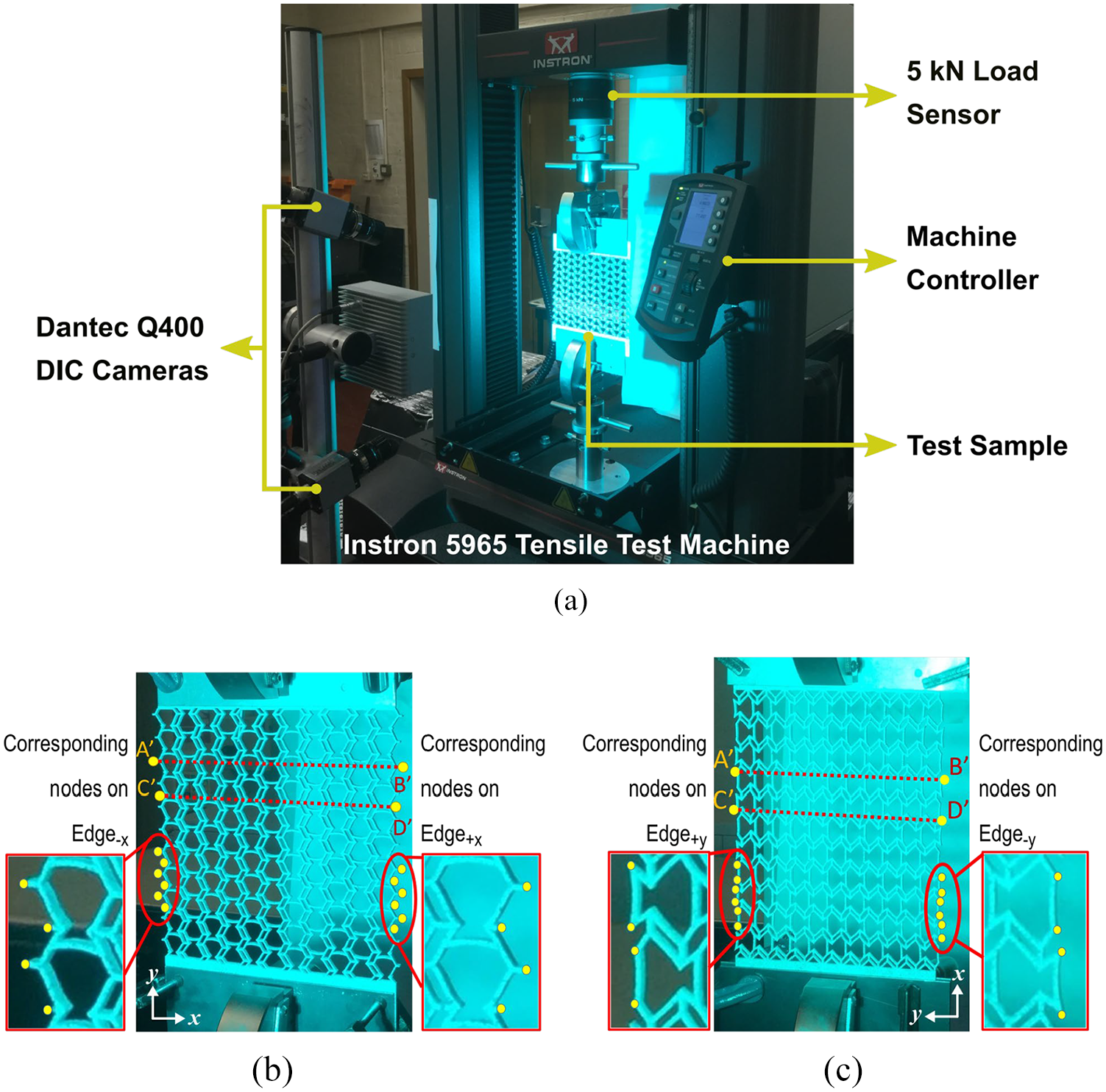
(a) Tensile test setup including digital image correlation (DIC) gear for measurement of strains and Poisson’s ratio, (b) deformed Fish Cells metamaterial under loading in the y-direction that illustrates the position of corresponding nodes on Edge±x, and (c) deformed Fish Cells metamaterial under loading in the x-direction that illustrates the position of corresponding nodes on Edge±y.
Figure 7 shows the force–displacement diagrams of metamaterial samples in x- and y-direction. The failure load of experimental metamaterial samples in x- and y-direction is 659.3 and 628.9 N as well as failure displacement of 23.0 and 41.7 mm in x- and y-direction, respectively. The ultimate displacement capacity of the metamaterial in the y-direction is approximately 1.8 times larger than x-direction. This can be justified by considering the deformation mechanism of the Fish Cell under loading in the x- and y-direction as shown in Figure 7(b) and (c), respectively. Three ribs of a Fish Cell annotated as R1, R2, and R3 and the contours of the rotation are plotted in the figures. It is only under loading in y-direction that the rib R2 rotates and contributes to the total strain. While, under loading in the x-direction, the rib R2 does not rotate and only equal rotations of ribs R1 and R3 contribute to the strain. Therefore, the strain in the y-direction is larger than x-direction for the same stress level. Hence, for applications where large deformations are required, installation of metamaterial with loading along y-direction shall be considered. Moreover, the variation of structural stiffness in the y-direction is smaller than x-direction and maintains stiffness value up to failure, while metamaterial shows softening behavior along the x-direction.
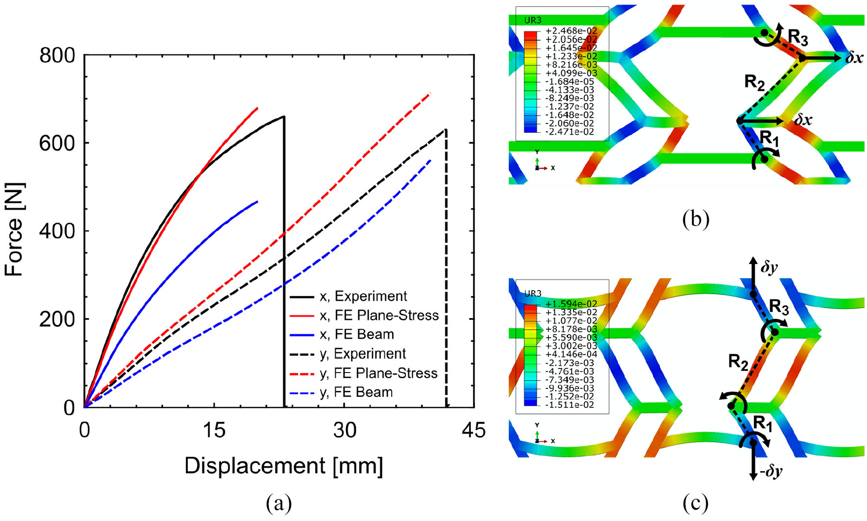
(a) Force–displacement diagrams of metamaterial samples in x- and y-direction obtained from experiment and FE simulations, (b) schematic illustration of the ribs bending under loading in the x-direction and (c) y-direction that are plotted over the planar rotation contours obtained from FE simulation.
4.4. Results and discussion
4.4.1. Validation
In this section, results of the experiments and numerical analysis performed on Fish Cells metamaterial are compared to investigate the validity of numerical models. Two models of manufactured samples, that is, beam structure and continuum solid structure, with dimensions presented in section “Fish Cells metamaterial’s architecture” and material properties presented in section “Material characteristics” are simulated in ABAQUS. Beam elements, as described in section “Finite element method analysis,” and 2D continuum quadratic plane-stress elements, known as CPS8, are used for numerical analysis. Mesh convergence studies are performed, and fine mesh discretization with a global size of 0.125 mm is applied for plane-stress elements. Figure 7(a) shows force–displacement curves of the two models in x- and y-directions. FEM model using beam elements has lower stiffness compared to the experiments, while the model with 2D plane-stress elements fits better to the experimental curves in both x- and y-directions. The maximum error between predicted stiffness using 2D plane-stress model and experiment is less than 10% and 5% in the x- and y-direction, respectively.
Poisson’s ratio in x- and y-directions are calculated by measuring displacements of the ABCD rectangle vertices on numerical and experimental models, where DIC system is used to obtain displacement field and strain contours of the metamaterial samples as presented in Appendix 2. Poisson’s ratio νyx calculated from simulation with beam elements is νyx = 0.00001, while νyx = 0.0488 and νyx = 0.0463 from simulation with CPS8 elements and experiment, respectively. In the other direction, Poisson’s ratio νxy calculated from a simulation with beam elements is νxy = 0.0003, while νxy = 0.2087 and νxy = 0.2265 from a simulation with CPS8 elements and experiment, respectively. The Poisson’s ratios measured from the experiment and numerical model with 2D plane-stress elements are close with less than 8% relative error. The reason for the difference between numerical results with beam and continuum solid models is discussed in the next section.
4.4.2. Modeling approach, element discussion
As explained, the desired values for Poisson’s ratio are those obtained by the numerical model using beam elements; however, the details of the manufactured samples resulted in Poisson’s ratio larger than those predicted by beam model. Chen and Fu (2018) have also reported different results for cellular structure modeled with beam and solid elements. The difference between the two modeling approaches is due to the complex deformations at joints, which is not explicitly captured using the beam element. When tuning the Poisson’s ratio for a specific value, the joints should be thin comparing to the ribs to be ideal (Bauer et al., 2017; Bückmann et al., 2014) as considered in the design and mathematical modeling of extremal materials as well (Milton, 1992; Milton and Cherkaev, 1995). If joints are not ideal and beam model is used, the joints’ rigidity will result in different Poisson’s ratio (Brighenti et al., 2016). Using the beam model that represents an ideal joint, the Fish Cells geometry reaches perfect ZPR behavior, where the interface of ribs and connectors for transferring the load is only a single node. However, considering uniform thickness of the members in manufactured samples, the material builds up at the joints and the thickness at joints has becomes larger than ribs as shown in Figure 8(b). Therefore, load transfers along the entire area of the joint’s cross section rather than a single node. In this regard, continuum solid models that are closer to the experiment should be used to justify the ZPR behavior of the Fish Cells metamaterial. In addition, the stress concentration at joints is predicted in the plane stress model that results in the accurate prediction of global structure stiffness and deformation. Moreover, aiming to reach the substantially ZPR behavior, a modified Fish Cell with reduced thickness at joints is presented to investigate the ideal joint using solid model as shown in Figure 8(c). The thickness at the joint is 0.1 times the thickness of the rib, and a chamfer angle of 20° with respect to the rib’s midline is applied in the joints. Identical dimensions and material properties as other models are used, and tessellation number of experiments is considered for the joint thickness effect study, that is, (5 × 5) s . Since the solid FE model with CPS8 elements in ABAQUS is verified with experimental results, it is used similarly to evaluate the thickness reduction effect. Hence, the discretization is locally refined at the joints where the element size reduces from 0.125 to 0.01 mm for great accuracy.
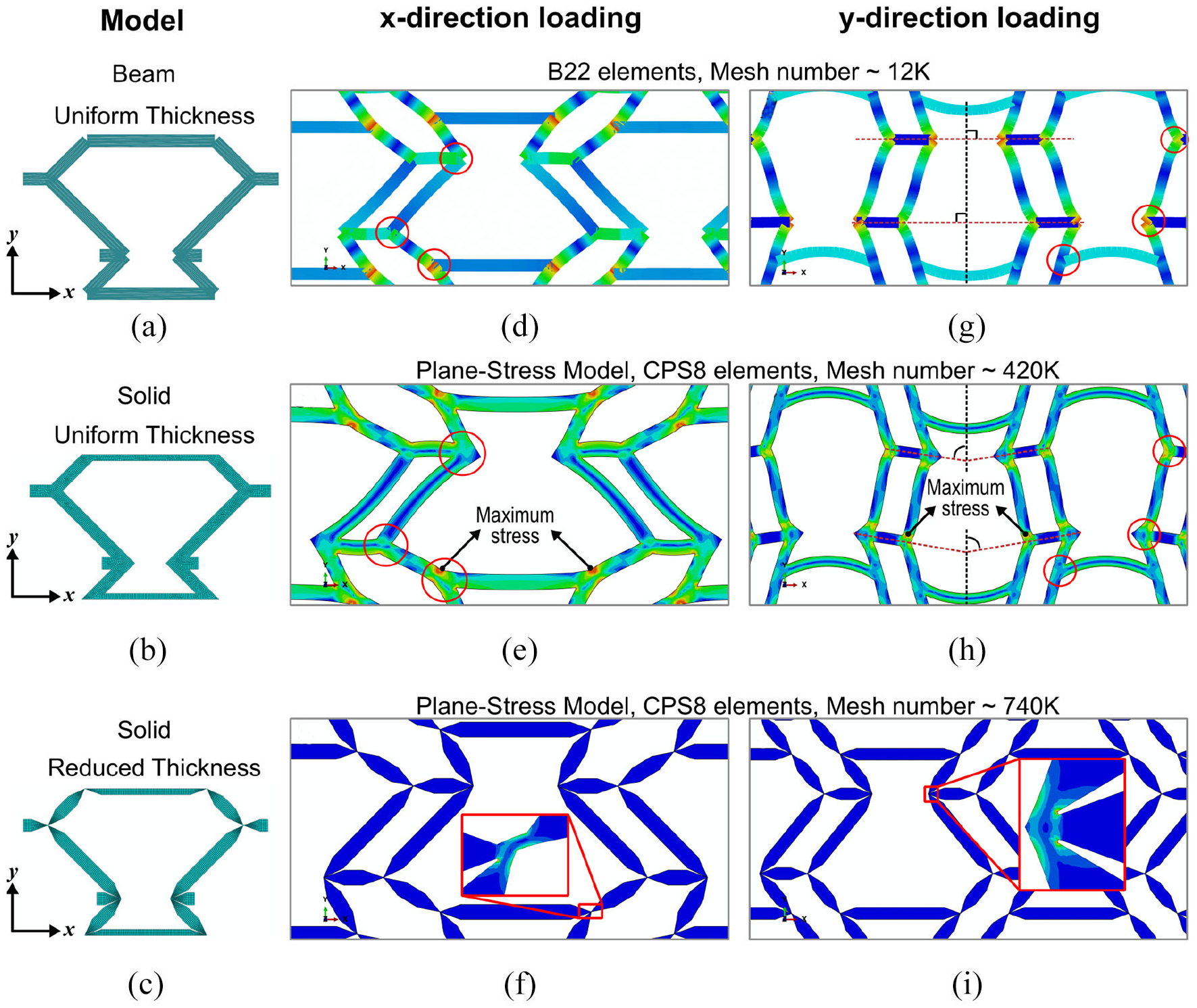
Fish Cell: (a) beam model with uniform thickness, (b) solid plane-stress model with uniform thickness, and (c) solid plane-stress model with reduced thickness at joints. Deformed shape and stress contour of the Fish Cells tessellation under tension in the x-direction with (d) beam model, (e) solid model with uniform thickness, and (f) solid model with reduced thickness at joints. Deformed shape and stress contour of the Fish Cells tessellation under tension in the y-direction with (g) beam model, (h) solid model with uniform thickness, and (i) solid model with reduced thickness at joints.
In order to understand the effect of modeling approach on the results, beam and solid models are compared. Under tension in the x-direction in the beam model, the re-entrant part of the cell expands as much as hexagonal section contracts, resulting in zero displacements in the orthogonal direction of the Fish Cells as shown in Figure 8(d). In the plane-stress model as annotated in Figure 8(e), the maximum stress is observed at the connection of the rib with the base member where the bending moment is maximum. Von Mises stress at this point when 1-mm displacement is applied is 13.6 and 7.1 MPa for plane-stress and beam models, respectively. This large difference is contributed to the stress concentration that can be captured using plane-stress model. The high stress concentration at this point leads to larger rotation of the bending rib in solid model than beam model, that is, larger contraction in the orthogonal direction; therefore, the metamaterial experiences PPR. In addition, base members in the beam model do not experience any moments, while in plane-stress model these members do not have uniform stress distribution through thickness, which results in bending moment and curved profile.
Under loading in the y-direction in the plane-stress model, the maximum stress is observed at the joint shared between the connector and the ribs, as annotated in Figure 8(h). Von Mises stress at this point is 13.80 and 6.54 MPa for plane-stress and beam models when 2-mm displacement is applied. Comparison of Figure 8(g) and (h) reveals the rotation of connectors in the plane stress model, while there is no rotation in the beam model. This rotation of connectors in the plane stress model causes contraction in the x-direction and PPR. The difference of the stress contour in joints due to the stress concentration is highlighted in Figure 8(d) to (i).
Justifying the ZPR behavior of the Fish Cells metamaterial using solid model, the tessellation with reduced thickness at joints is simulated under global strain of 1% in each direction. Figure 8(f) and (i) represent the stress contour of the deformed tessellations in the x- and y-direction for the reduced thickness model, respectively. The contour of the stress is better visible at joints in the magnified views because the stress concentrates at the reduced joints and results in the hinging mechanism. The Poisson’s ratio of this model is νxy = −0.0617 and νyx = −0.0071 that show significant improvement and substantially ZPR behavior comparing to the uniform thickness model.
As a conclusion, thickness reduction at joints for further improvement of the Poisson’s ratio value is justified. Therefore, the substantially ZPR behavior of the Fish Cells metamaterial is proved, which was also demonstrated using beam model. In this regard, it is suggested to consider reducing the thickness at joints when a metamaterial design for a specific Poisson’s ratio value such as zero is tuned. Figure 8 also highlights the approximate number of elements used in the simulation of each FE model. Considering the computation time and complexity of the geometry and fine mesh generation of the solid models with reduced thickness, the beam model can be an effective tool for design purposes; therefore, beam model is employed for integration studies.
5. Structural integrity for morphing application
Morphing technology has diverse applications in many sectors including aerospace, automotive, biomechanics, and renewable energy systems. Focusing on aerospace vehicles, morphing may refer to tools and methods used to improve the aerodynamic efficiency and increase performance by setting up the optimum geometry and configuration of the structure. In this case, the main challenge for the development of morphing structures is a suitable morphing skin for providing a smooth aerodynamic surface, transferring the distributed aerodynamic loads to the main structural elements, and enabling large shape changes through large strain capacity in actuation direction. Hence, low in-plane stiffness and high out-of-plane stiffness are needed in the design of morphing skins to enable large shape changes with low actuation power and to transfer aerodynamic loads efficiently.
5.1. Morphing skins and fish cells metamaterial
The proposed skins for morphing aircraft are usually made of elastomeric covers supported by a core with different geometries and deformation mechanisms, for example, a flexible skin made of a corrugated core and elastomer coatings (Dayyani et al., 2013, 2014, 2015b; Dayyani and Friswell, 2017; Ermakova and Dayyani, 2017). The main advantage of corrugated cores is the anisotropic behavior, that is, stiffness along the corrugation direction while flexibility in the transverse direction. Corrugated cores have also other remarkable characteristics such as high strength to density ratio, good energy absorption, and easy fabrication (Dayyani et al., 2015a). However, the intrinsic weakness of a corrugated core is thickness reduction under deformation, resulting in a significant decrease in moment of inertia and bending stiffness. A solution may be using cellular structures like honeycombs for the core of morphing skins. Although honeycombs satisfy thickness requirements, they have PPR that leads to the dependency of longitudinal and transverse stresses. In other words, actuation in morphing direction causes stress in the orthogonal direction. Applying constraints on side edges of morphing skin without causing stiffness augmentation in the actuation directions is a key requirement for skin integration in morphing applications.
Metamaterials with ZPR behavior could be very beneficial for morphing application because of preventing stiffness augmentation and unclastic curvature, which provides better geometric conformability. Substituting ZPR metamaterials with conventional honeycombs can solve the PPR issues. Using Fish Cells metamaterial in morphing skin, stiffness augmentation issues should be solved as the stress coupling will no longer exist. This section demonstrates the capability of Fish Cells metamaterial in removing stiffness augmentation under deformation with constraints on side edges, representing an assembly of the skin to the main structure.
5.2. Edge smoothness and boundary conditions
Although in theory, a homogenized Fish Cells metamaterial exhibits ZPR behavior in two orthogonal directions, in practice perfect ZPR behavior might not be achieved due to size ratio of unit cell to tessellations limited with the current manufacturing technology or applying constraints which may cause local deformations at the edges imposed by boundary conditions, as discussed in section “Homogenization.” Therefore, it is important to have a criterion for evaluating integration performance such as edge smoothness and debonding stress where the local deformations at the boundaries are investigated.
In this regard, Poisson’s ratio definition is expanded by introducing edge smoothness denoted by S to study the edge deformations and the local effects of boundary conditions. While Poisson’s ratio of the metamaterial is obtained by measuring strains on ABCD rectangle (shown in Figure 2), edge smoothness is defined between two corresponding nodes on two opposite edges connected by a straight virtual line as shown in Figure 6(b) and (c). The corresponding nodes on Edge+x and Edge−x, with normal vectors in +x and −x directions, are located on the free ends of connectors as shown in Figure 6(b). Similarly, the corresponding nodes on Edge +y and Edge−y, with normal vectors in +y and −y directions, are located on the intersection of the base and bending rib (corners of the cells), as depicted in Figure 6(c). The edge smoothness S that measures the change of the distance between two opposite edges is defined as
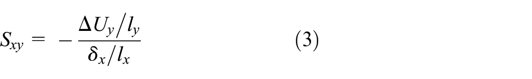
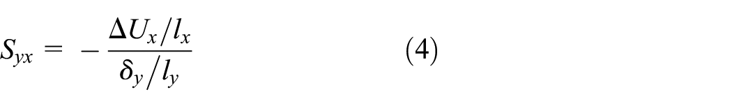
In equation (3), ΔUy is the difference between displacements of corresponding nodes on Edge
+y
and Edge−y
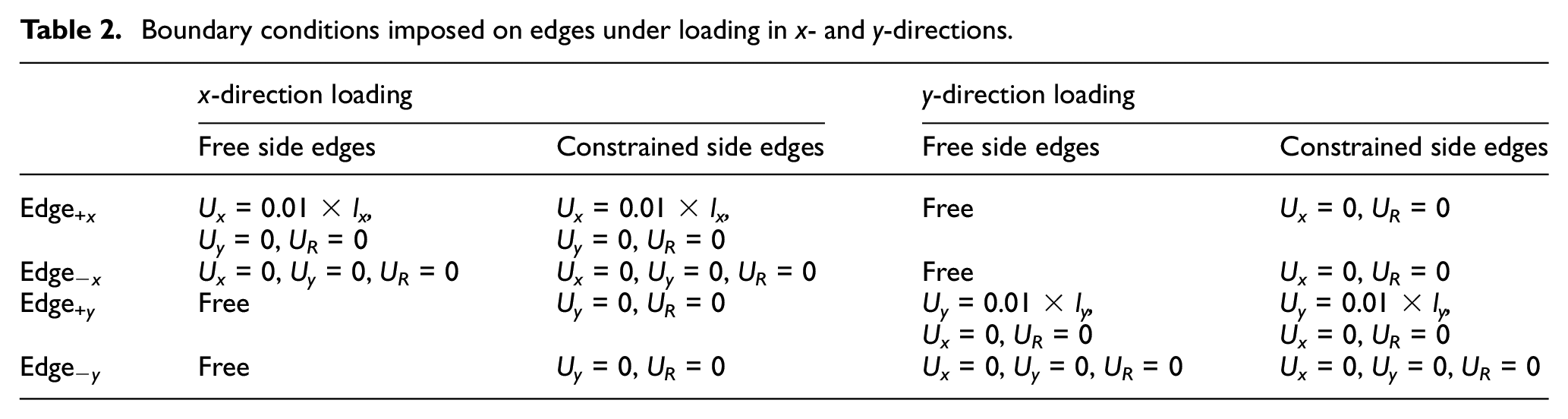
Boundary conditions used for morphing skin with Fish Cells core are presented in Table 2 where lateral edges of the metamaterial samples are assessed in both free and constrained conditions. Edge +y and Edge−y are considered as side edges in x-direction loading and Edge +x and Edge−x are side edges in y-direction loading as shown in Figure 2(c) and (d), respectively.
Boundary conditions imposed on edges under loading in x- and y-directions.
5.3. Edge smoothness homogenization
It is important to perform the edge smoothness study on a tessellation with a homogenized behavior. Hence, a numerical study is done using a beam model as described in section “Finite element method analysis” with different tessellation numbers. Figure 9 shows edge smoothness Sxy and Syx versus normalized length of the metamaterial for 5 × 5, 10 × 10, and 20 × 20 tessellation numbers. For each tessellation, the strain imposed on the moving edge is equal to 1%. This strain range is consistent with maximum strain requirements for a flexible skin in camber morphing (Gandhi and Anusonti-Inthra, 2008).
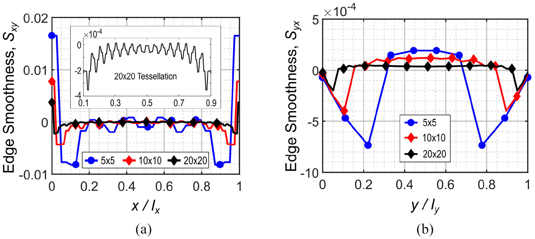
Edge smoothness homogenization analysis in two orthogonal directions for 5 × 5, 10 × 10, and 20 × 20 tessellations: (a) Sxy where load is applied on Edge+x in the x-direction and (b) Syx where load is applied on Edge+y in the y-direction.
The local deformations near the boundaries cause Sxy to have absolute values larger than zero, which is due to clamp boundary conditions. Value of Sxy is shown in Figure 9(a), where 20 × 20 tessellation has the least affected edge smoothness by local deformations due to the boundary conditions, while Sxy is substantially zero far from boundaries in 5 × 5 and 10 × 10 tessellations. For 20 × 20 tessellation, magnitudes of the edge smoothness Sxy are affected by boundary conditions in less than 10% of the domain length from each side. In this regard, the magnified diagram in Figure 9(a) illustrates the edge smoothness Sxy over the x/lx = (0.1, 0.9) range where the magnitudes are from the order of 10−4. The pattern of the edge smoothness Sxy is symmetric due to symmetric boundary conditions. This justifies considering ABCD rectangle in the center of the metamaterial to measure Poisson’s ratio. As the number of tessellation increases, boundary condition effect decreases and edge smoothness tends to zero for a larger range of tessellation length.
5.4. Edge smoothness Sxy and stiffness analysis for loading in the x-direction
This section discusses the effect of symmetry along y-direction on the edge smoothness Sxy. In this regard, two cases of 20 × 20 and (20 × 20) s tessellations are compared in Figure 10(a). Although both cases demonstrate a similar trend, the 20 × 20 tessellation shows small repeating fluctuations which are due to shear–extension coupling found in Fish Cells metamaterial, as depicted in Figure 10(b). However, for a very large tessellation, the effect of symmetry is negligible as it is in the same order as deformations. The edge smoothness Sxy is symmetric in both cases along the length of metamaterial as shown in Figure 10(a), which is because of the symmetric boundary conditions of the edges.
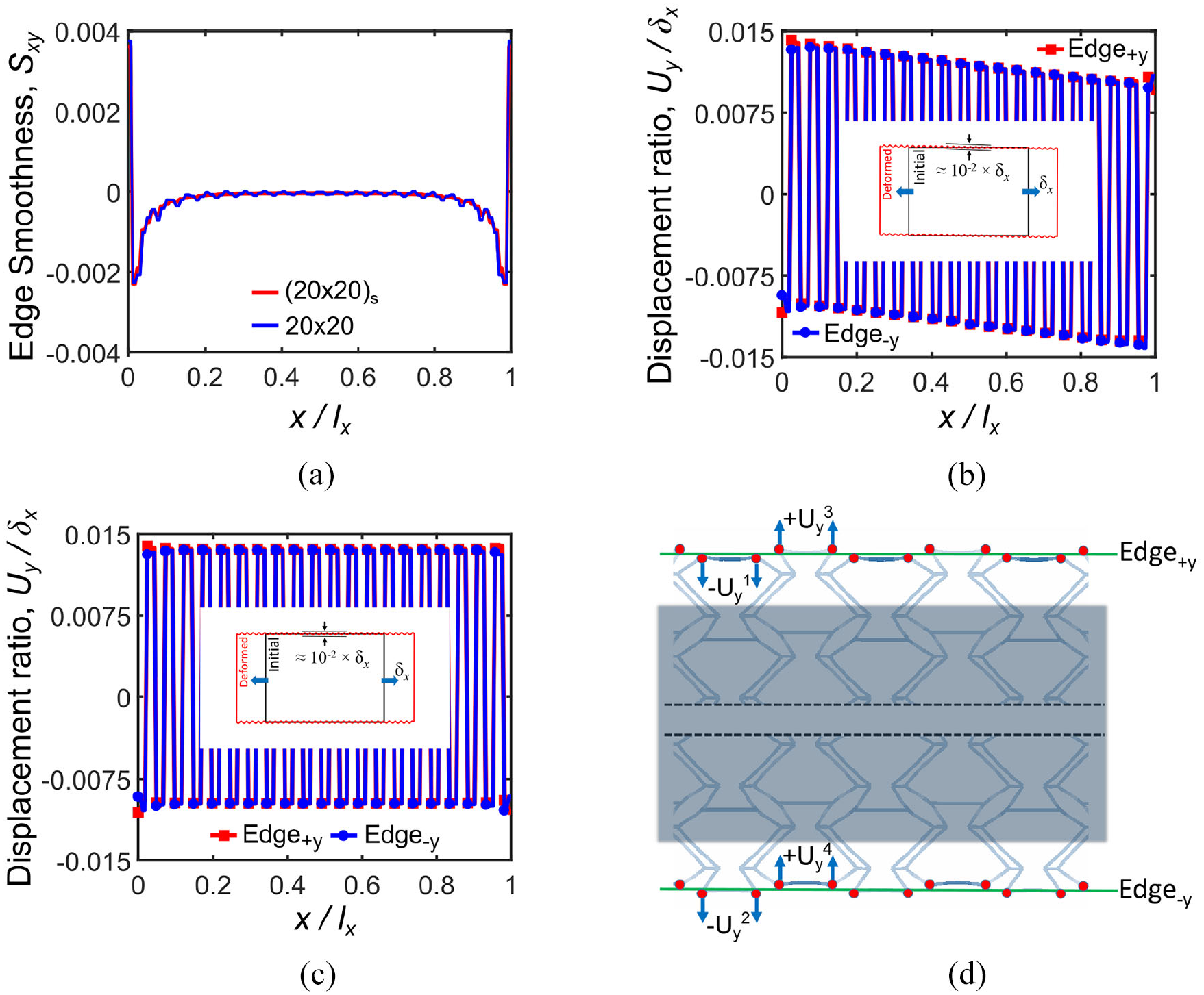
Edge smoothness Sxy analysis for loading in the x-direction: (a) for 20 × 20 and (20 × 20) s tessellation numbers, (b) displacement ratio of nodes located on Edge+y and Edge−y for 20 × 20 tessellation, (c) displacement ratio of nodes located on Edge+y and Edge−y for (20 × 20) s tessellation, and (d) schematic of displacements of the corresponding nodes on Edge+y and Edge−y.
Figure 10(b) and (c) show the ratio of nodal displacements for both cases of 20 × 20 and (20 × 20)
s
along Edge
+y
and Edge−y as demonstrated in Figure 10(d). The displacements of nodes located on hexagonal cells of Edge
+y
and corresponding nodes located on the re-entrant cell of Edge−y are
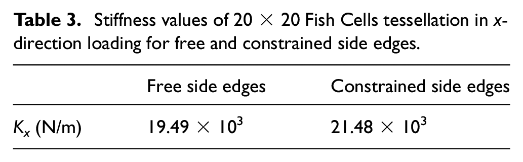
Table 3 presents the stiffness values of 20 × 20 Fish Cells tessellation in the x-direction for free and constrained side edges expressed earlier in Table 2. The results show that the stiffness of Fish Cells metamaterial with constrained side edge is 10% larger than the stiffness of metamaterial with free side edges. Hence, stiffness augmentation may be defined as this structural stiffness ratio, that is, Kx_constrained/Kx_free = 1.10.
Stiffness values of 20 × 20 Fish Cells tessellation in x-direction loading for free and constrained side edges.
5.5. Edge smoothness Syx and stiffness analysis for loading in the y-direction
Figure 11(a) illustrates the edge smoothness Syx for 20 × 20 and (20 × 20) s tessellations where the effect of the symmetry on the edge smoothness is shown. Figure 11(b) and (c) show the ratio of nodal displacements for 20 × 20 and (20 × 20) s tessellations along Edge +x and Edge−x as demonstrated schematically in Figure 11(d) and (e), respectively. The symmetric (20 × 20) s tessellation has a zigzag trend of edge smoothness Syx, while 20 × 20 tessellation has a smooth and substantially zero Syx due to antisymmetric positions of re-entrant (r) and hexagonal (h) cells as shown in Figure 11(d) and (e). For asymmetric tessellations, two corresponding nodes belong to different r and h cells, which move with the same magnitude in the same direction as shown in Figure 11(d), therefore ΔUx = 0 and a smooth trend is achieved. However, for symmetric tessellations two corresponding nodes belong to the same cells, that is, r–r or h–h, which move with the same magnitude in the opposite directions as shown in Figure 11(e). Therefore, ΔUx ≠ 0 and the virtual line between them will either stretch or compress; that is, negative Syx due to expansion or positive Syx due to contraction.
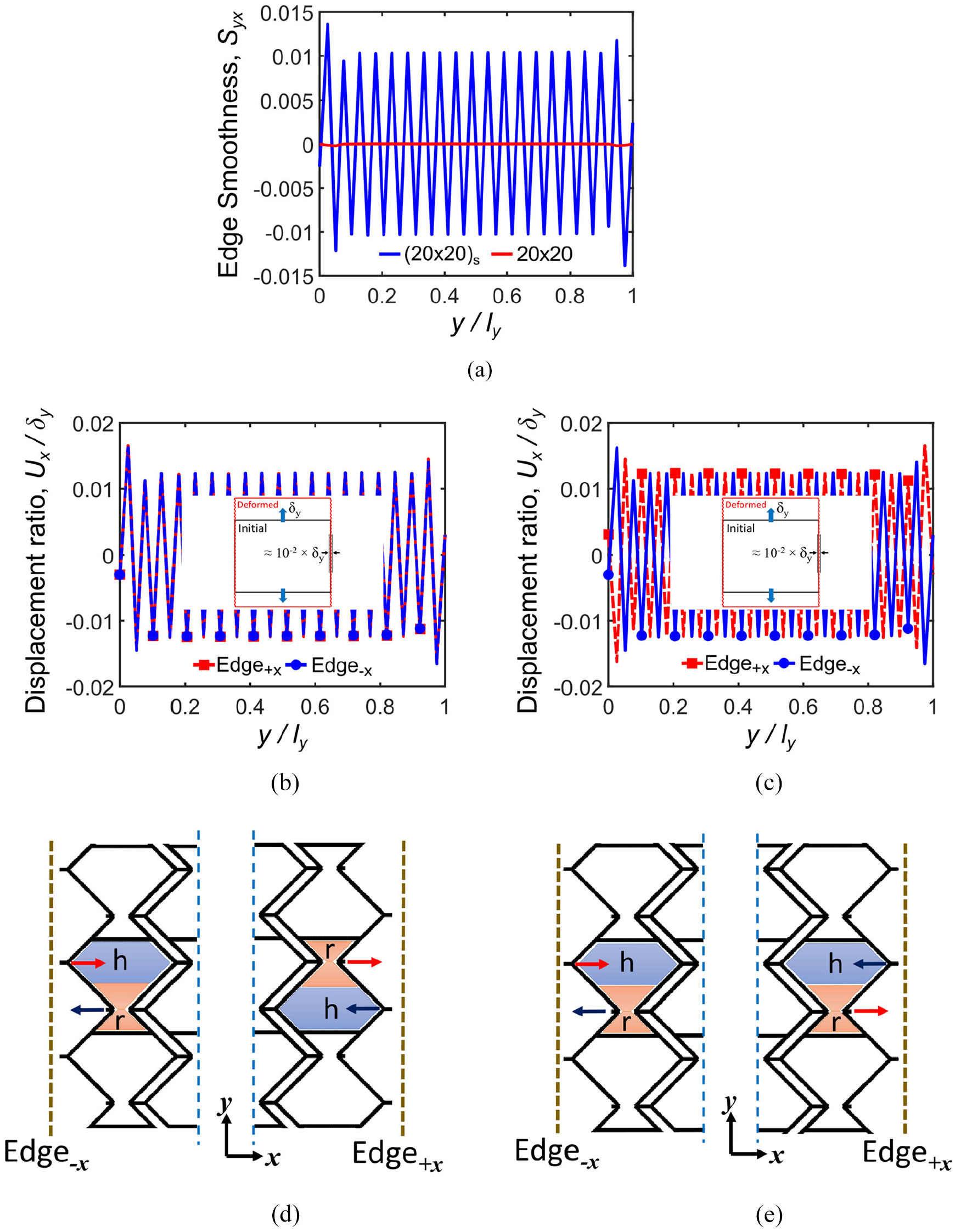
Edge smoothness Syx analysis for loading in the y-direction: (a) for 20 × 20 and (20 × 20) s tessellation numbers, (b) displacement ratio of nodes located on Edge+x and Edge−x for 20 × 20 tessellation number, (c) displacement ratio of nodes located on Edge+x and Edge−x for (20 × 20) s tessellation number, (d) antisymmetric positions of re-entrant (r) and hexagonal (h) parts of the cell for asymmetric 20 × 20 tessellation and the corresponding nodes’ displacement vector, and (e) symmetric positions of re-entrant (r) and hexagonal (h) parts of the cell for symmetric tessellations and the corresponding nodes’ displacement vector.
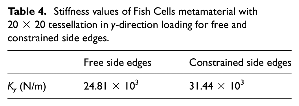
Table 4 presents the stiffness values of Fish Cells metamaterial with 20 × 20 tessellation in the y-direction for free and constrained side edges expressed earlier in Table 2. The results show that the stiffness value of Fish Cells metamaterial with constrained side edge is about 27% larger than the stiffness value of metamaterial with free side edges, that is, Ky_constrained/Ky_free = 1.27. Although not very large, this stiffness augmentation in y-direction loading is due to the locations of corresponding nodes on connectors’ free end of Edge−x and Edge +x , as shown in Figure 6(b). These nodes have large displacements under loading due to bending of ribs; hence, large reaction forces are expected when they are constrained.
Stiffness values of Fish Cells metamaterial with 20 × 20 tessellation in y-direction loading for free and constrained side edges.
5.6. Design perspective
The obtained results show the effect of tessellation’s symmetry along y-direction as follows:
For asymmetric tessellations, Syx trend is smooth and substantially zero but Sxy will have small fluctuations due to shear–extension coupling.
For symmetric tessellations, Syx has zigzag trend and non-zero values but Sxy will have smooth trend because shear–extension coupling does not exist and values are close to zero.
Therefore, the primary direction for morphing integration can be determined. Shear–extension coupling might be a positive aspect of the design in some applications where desirable shear displacement is resultant of tension or similarly, desirable torsion is resultant of axial tension in cylindrical tessellations.
5.7. Edge modification
The stiffness augmentation of the Fish Cells metamaterial is shown to be small under loading with clamp side edges. However, further topology enhancements on the edges are proposed in this section to reduce the stiffness augmentation further. The proposed enhancement for the geometries of Edges ±y is shown in Figure 12(a) where Fish Cells are removed alternately. In addition, the proposed enhancement for the geometries of Edges ±x includes an additional half of Fish Cells for each edge, as highlighted in Figure 12(b). FE analysis on structures with modified edges is performed using dimensions presented in section “Fish Cells metamaterial’s architecture” and parameters discussed in section “Finite element method analysis.” Boundary conditions and loading are also according to Table 2; therefore, results of edge enhancement can be compared to conventional edges.
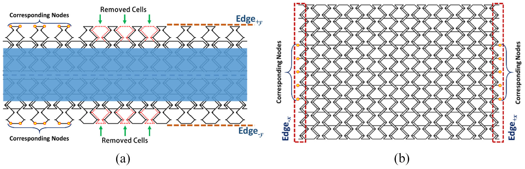
(a) Enhanced geometries of Edges±y with alternately removed Fish Cells and (b) enhanced geometries of Edges±x with an additional half of Fish Cells.
5.7.1. Discussion of enhanced Sxy
Figure 13 highlights the positive effect of Edge ±y enhancements on edge smoothness Sxy. The geometry of the enhanced and conventional Edge +y is compared in Figure 13(a) where uniform displacement contour is observed for enhanced geometry. The displacement of the corresponding nodes on the Edge ±y in the y-direction is very small. This is because the cells in the enhanced design are not loaded through connectors due to the removal of one Fish Cell of each unit cell. Therefore, the reaction forces reduce significantly, when Edge ±y are constrained resulting in stiffness augmentation alleviation.
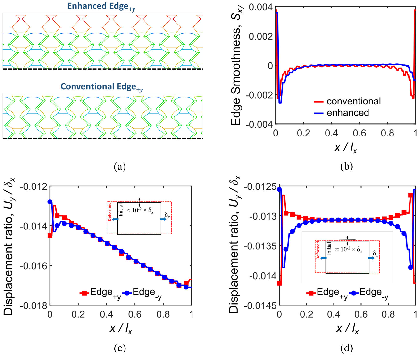
Edge enhancement effect on displacement ratio and edge smoothness Sxy: (a) enhanced and conventional edge deformations under tension in the x-direction, (b) comparison of edge smoothness Sxy for 20 × 20 and (20 × 20)enhanced tessellations, (c) displacement ratio of corresponding nodes located on Edges±y for (20 × 20)enhanced tessellation, and (d) displacement ratio of corresponding nodes located on Edges±y for
Sxy has maintained the substantially zero values far from the boundaries, as shown in Figure 13(b). Figure 13(c) shows the displacement ratio of corresponding nodes on Edge +y and Edge−y for the (20 × 20)enhanced tessellation, where shear–extension coupling occurs due to tessellation asymmetry along the y-axis. Moreover, the fluctuation of displacements is removed and values are positive compared to Figure 10(b).
Figure 13(d) shows the displacement ratio of corresponding nodes on Edge
+y
and Edge−y for the enhanced
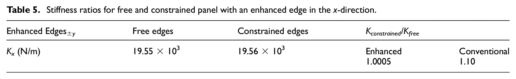
The most important achievement due to this edge enhancement is improving the stiffness augmentation ratio, as presented in Table 5 where stiffness remains approximately constant for both cases of free and constrained side edges. This means that Fish Cells metamaterial has excellent integration capabilities in addition to its ZPR performance in the x-direction.
Stiffness ratios for free and constrained panel with an enhanced edge in the x-direction.
5.7.2. Discussion of enhanced Syx
The deformed geometries of conventional and enhanced Edge−x are compared in Figure 14(a). Under loading in the y-direction, the base of the Fish Cell bends without displacement in the x-direction, while the connectors have large displacements in the x-direction. Therefore, the proposed enhancement results in the integration of the Edges ±x of metamaterial via base members, that is, the constraints are applied at the center of the base members. Hence, a uniform displacement contour is achieved by the enhanced geometry that results in edge smoothness improvement and alleviates stiffness augmentation further.
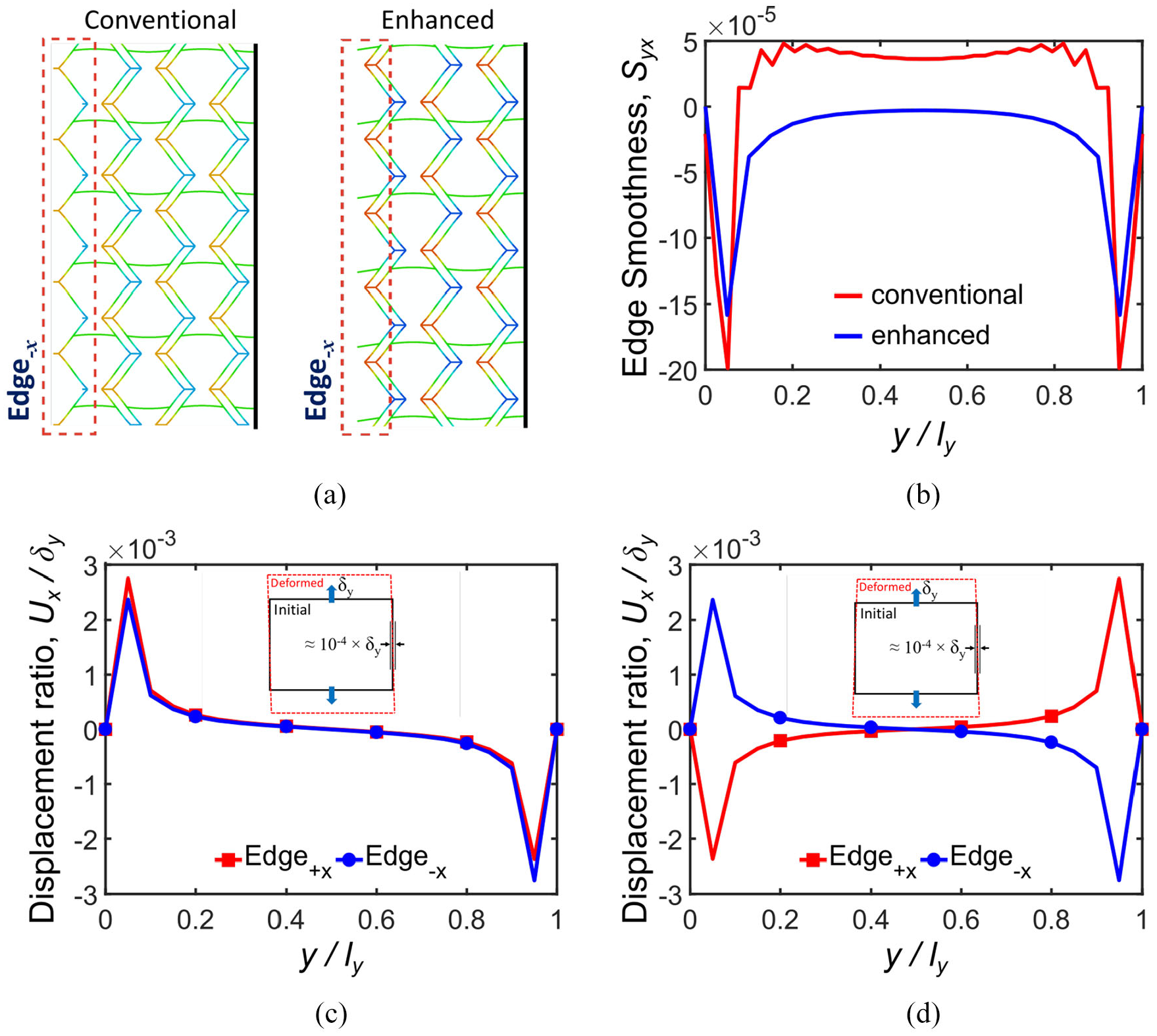
Edge enhancement effect on displacement ratio and edge smoothness Syx: (a) enhanced and conventional edge deformations under tension in the y-direction, (b) comparison of edge smoothness Syx for (20 × 20)enhanced and 20 × 20 tessellations, (c) displacement ratio of corresponding nodes located on Edges±x for (20 × 20)enhanced tessellation, and (d) displacement ratio of corresponding nodes located on Edges±x for
The positive effect of Edges
±x
enhancements on edge smoothness Syx is shown in Figure 14(b) where the enhanced edges present one order of magnitude smaller values than conventional edges. Figure 14(c) depicts the nodal displacement ratio of enhanced Edge
+x
and Edge−x for (20 × 20)
enhanced
tessellation, which exhibits an antisymmetric trend. In contrast to the conventional edge, the edge smoothness Syx for enhanced geometry is not dependent on tessellation symmetry along y-direction, because metamaterial skin is connected to the external frame via Fish Cells base instead of connectors. In this regard, nodal displacements of (20 × 20)
enhanced
and
The most important achievement by this edge enhancement is improving the stiffness augmentation ratio as presented in Table 6, where stiffness remains substantially constant for both cases of free and constrained side edges. This means that the Fish Cells metamaterial has excellent integration capabilities in addition to its ZPR performance in the y-direction.
Stiffness ratios for free and constrained panel with an enhanced edge in the y-direction.

6. Conclusion and remarks
Fish Cells as a new mechanical metamaterial is proposed with ZPR in two planar directions. Homogenization study is performed on Poisson’s ratio and effective elastic modulus in two directions to obtain the right scale of the metamaterial unit cell. Numerical analysis corroborates the ZPR behavior of Fish Cells design in two directions for a homogenized tessellation. The experimental study validated the Poisson’s ratio measurement and elastic–plastic behavior of the samples in both directions. A detailed discussion on the effect of the joints is presented by the analysis of the metamaterial using beam and plane-stress models. In addition, the reduced thickness solid model is presented justifying ZPR behavior of the Fish Cells metamaterial architecture.
The application of the Fish Cells metamaterial as the core of morphing skin is considered and integration of metamaterial with morphing structures is critically discussed, where requirements such as relieving stiffness augmentation and fine edge geometry are considered. Edge smoothness is defined as a criterion to assess edge integration of the metamaterial in both orthogonal directions. Concepts for geometric edge enhancements are proposed to further improve stiffness augmentation as the main issue in the development of morphing structures. The numerical studies on homogenized tessellations with enhanced edges show that Fish Cells metamaterial has perfect integration capabilities and achieves substantially zero stiffness augmentation. In addition, Fish Cells metamaterial offers the flexibility for the designer to create symmetric and asymmetric tessellations that can have different edgewise deformations. In case of asymmetry, Fish Cells metamaterial presents extension–shear coupling, which is a very important advantage for applications where bending-twist in out of plane direction is required such as twisting in large span wings under bending. The future study may include topology and shape optimization for maintaining ZPR over large strain range.
Footnotes
Appendix 1
Appendix 2
Declaration of conflicting interests
The author(s) declared no potential conflicts of interest with respect to the research, authorship, and/or publication of this article.
Funding
The author(s) received no financial support for the research, authorship, and/or publication of this article.