
Abstract
The aero-structural design of an adaptive vortex generator for repeatable, elastic, deployment and retraction from an aerodynamically clean surface is presented. A multidisciplinary objective function, containing geometrically nonlinear finite element analysis and large eddy simulation, is used to derive the optimal adaptive geometry for increasing the momentum of the near-wall fluid. It is found that the rapid increase of in-plane membrane stress with deflection is a significant limitation on achievable deformation of a continuous skin with uniform section. Use of a 2D auxetic lattice structure in place of the continuous skin allows for significantly larger deformations and thus a significant improvement in performance. The optimal deformed geometry is replicated statically and the effect on the boundary layer is validated in a wind tunnel experiment. The lattice structure is then manufactured and actuated. The deformed geometry is shown to compare well with the FEA predictions. The surface is re-examined post actuation and shown to return to the initial position, demonstrating the deformation is elastic and hence repeatable.
Introduction
This paper presents the optimal design of an adaptive vortex generator for delaying the separation of a fluid boundary layer from an aerodynamic surface. Boundary layer separation is a significant limitation in the peak performance of high-lift aerofoil configurations such as those used for take-off and landing. Due to the impact of separation on aircraft safety and performance, a significant body of research exists on the application of static structures termed vortex generators on wings for this purpose. However, as will be described, the application of static vortex generators is accompanied by a loss of system efficiency at the off-design conditions which account for the majority of operational use (Ashill et al., 2001). This variation in requirement is typical of systems which benefit from an adaptive solution.
For the majority of the upper surface of an aerofoil, the fluid passing over the surface is experiencing an adverse pressure gradient. This acts to retard the flow next to the surface until the streamwise velocity gradient perpendicular to the surface reaches a local minimum. At this point the flow streamlines, which had been following the profile of the aerofoil, depart the surface and separation occurs. This is associated with a loss of lift and a rapid increase in drag.
The most generally used method to prevent flow separation is the static vortex generator (VG). A multitude of designs and layouts of VG exist in the literature. Common variants of VG are illustrated in Figure 1 and include: inclined vanes (Taylor and Hoadley, 1948); wedges (Kuethe, 1971); and wishbones (Wheeler, 1991). Although the topology and positioning of these devices change, the underlying concept remains the same.
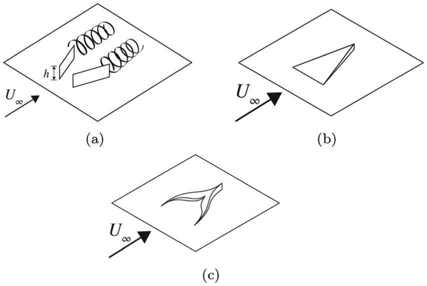
Illustration of conventional vortex generator types: (a) vane-type; (b) forwards wedge; (c) wishbone.
The application of VG in a boundary layer introduces a three-dimensional variation in the wetted geometry and so deflects the fluid from its original path. This produces a spanwise variation in pressure which, in conjunction with the viscous effects near the wall, results in a quantity of streamwise vorticity within the boundary layer (Lighthill, 1963). The trailing edge of these devices is typically sharp, resulting in a region of high pressure gradient which causes the boundary layer to separate. The streamwise vorticity produced by the VG is then shed into the flow where it forms a bound vortex as shown in Figure 1(a). The induced flow perpendicular to the wall provides a momentum transport mechanism through the boundary layer. This accelerates the flow near to the wing surface and counteracts the effect of the adverse pressure gradient, delaying separation at the expense of an increase in skin friction drag.
As VG are traditionally static, this mixing effect occurs at all flight conditions and so during cruise, when the flow is highly resistant to separation, the increase in near-wall momentum serves only to decrease system efficiency. Mitigation of the adverse off-design effects of VG have been investigated by: using low profile VG to contain the mixing within the boundary layer (Kuethe, 1971); mechanised deployment of VG through breaks in the aircraft skin (Joubert et al., 2013); and using synthetic air jets to provide the mixing and so having no physical device in the boundary layer (Glezer and Amitay, 2002). While these devices are effective, they still require gaps or breaks in the aircraft skin which are sources of parasitic drag.
An important challenge in commercial aircraft design is to increase the efficiency over the flight envelope. Of particular interest is the production of wings which maintain laminar airflow over a large proportion of the aerodynamic surface. Such aircraft would still require the critical stall prevention and performance modification that is currently provided by vortex generators. However, the presence of static mixing devices or breaks in the aerodynamic surface through which dynamic devices could be deployed, introduces a disturbance in the fluid boundary which promotes the onset of turbulent transition (Duncan et al., 2013). Boundary layer transition is an effective method of increasing the natural mixing of the boundary layer momentum and so preventing flow separation of an initially laminar boundary layer. The use of discreet roughness elements, very small excrescences from the wetted surface, have been shown to be effective at promoting transition and so reducing laminar separation (Simens and Gungor, 2014). However, as static features, the effect again remains regardless of the current need for flow control. The development of an adaptive surface which produces a similar mixing effect but which can be deployed and retracted from an aerodynamically clean surface as required, and thus only influencing the flow when and where necessary, is therefore of particular interest.
Under traditional rigid body design, the geometry of a wing is a compromise between the highly efficient thin, low camber, aerofoil optimal for cruise conditions and the high lifting performance of a thick, high camber, aerofoil necessary for take-off and landing. Typically the adaptation between these two conditions is achieved through the use of mechanisms to deploy discrete, geometry-altering, components such as flaps and slats from the wing (Torenbeek, 1979). These mechanisms allow the aircraft to deliver the desired performance at multiple points in the flight envelope from the same airframe.
The use of adaptive structures on aircraft aims to achieve a greater degree of flexibility by providing a continuous, rather than discretised, variation in geometry. This allows the aircraft to achieve a better solution to the current set of flight conditions than is possible with discrete components (Weisshaar, 2006). Additionally, in an adaptive design, the underlying structure provides the required geometry variation. This means that the breaks, gaps and cavities in the aircraft skin which are necessary in a mechanical solution are no longer needed.
A large body of research has been conducted on the production of morphing wings with precise applications determining the specific design requirements. A comprehensive review of morphing designs and actuation methods on aircraft has been produced by Barbarino et al. (2011) and for unmanned aerial vehicles by Gomez and Garcia (2011). Of these adaptive structures the majority deal with large-scale ‘global’ alterations to modify the wing performance by varying the whole wing geometry. Variable span wings have been developed which can be expanded or retracted to provide both optimal adjustment to system performance and roll authority (Ajaj et al., 2013). Structures with variable torsional stiffness have been used as wing supports which, when coupled with aerodynamic loads, provide a degree of twist control (Chen et al., 2000; Griffin and Hopkins, 1997).
The most prevalent application of morphing on aircraft is that of aerofoil profile variation. These methods can be broadly split into two groups: those which apply load directly to the aerofoil skin, and those which use topologically designed wing ribs to distribute an actuation load to the variable region. Applications where the actuation is applied directly to the skin include transonic shock control bumps (Jinks et al., 2016) and stall prevention through an oscillating suction surface (Jones et al., 2015). In these examples the variation in geometry is localised to the upper surface of the aerofoil, an area of low curvature, and the overall variation in geometry is small. For larger variations, the alteration of a section of the profile’s rib support allows a much larger change in geometry. Examples of such adaptive wing profiles include a variable geometry trailing edge flap (Kota et al., 2003), leading edge camber alteration (Santer and Pellegrino, 2009) and whole aerofoil variation (Woods and Friswell, 2012).
Not all flow control devices can be achieved with a global surface change, and devices such as shock control bumps, winglets, and vortex generators require a local geometry change which is finite in all directions. Examples of three-dimensional geometry change are rare, with the notable exceptions of Arrieta et al. (2013) and Rhodes (2012).
In their work on adaptive winglets, Arrieta and co-workers produced a bistable wingtip structure which could be selectively actuated between two configurations: that of a thin wing section, and a winglet for reducing induced drag. While this produces a large 3D variation in geometry, it requires the device to be unrestrained on three sides, which is not suitable for local actuation from a wing surface. In his work on adaptive shock control bumps Rhodes (2012) produced a demonstration model of a three dimensional adaptive approximation based on experimentally derived geometry. In this work, Rhodes used an optimisation algorithm to determine the actuation and boundary parameters to deform the geometry from a 0.4 mm thick aluminium skin using a finite element model and then produced an experimental demonstration. The finite element model closely matched the final morph but was only able to achieve
In this paper the development of a compliant surface which can be repeatably actuated to increase the resistance to separation of a turbulent boundary layer is presented. Initially, the aero-structural design optimisation process is described and then applied to a continuous surface of uniform section. A rapid increase of membrane stress is exhibited by this surface when producing the required geometry change which has non-zero curvature in both principle directions. This increase, coupled with the requirement for elastic deformation found with any repeatable morphing solution, severely constrains the design space and so limits the efficacy of the solution. In order to overcome this limitation a novel application of a 2D lattice is proposed to replace the uniform surface. The optimisation process is applied to the lattice structure and the resulting deployable compliant geometry is presented. The static deformed geometry is produced and tested experimentally to validate the computational fluid simulations and the lattice structure is produced to verify the finite element simulations.
Aero-structural design methodology
The design of any adaptive structure is a complex problem with many design variables. In the current work this is compounded by the highly nonlinear response of a boundary layer to geometry change and so a computationally expensive objective function must be used to quantify fitness (Garland et al., 2015). It is therefore infeasible to conduct a systematic search of the entire design space and instead, the optimisation process described in Figure 2 is used.
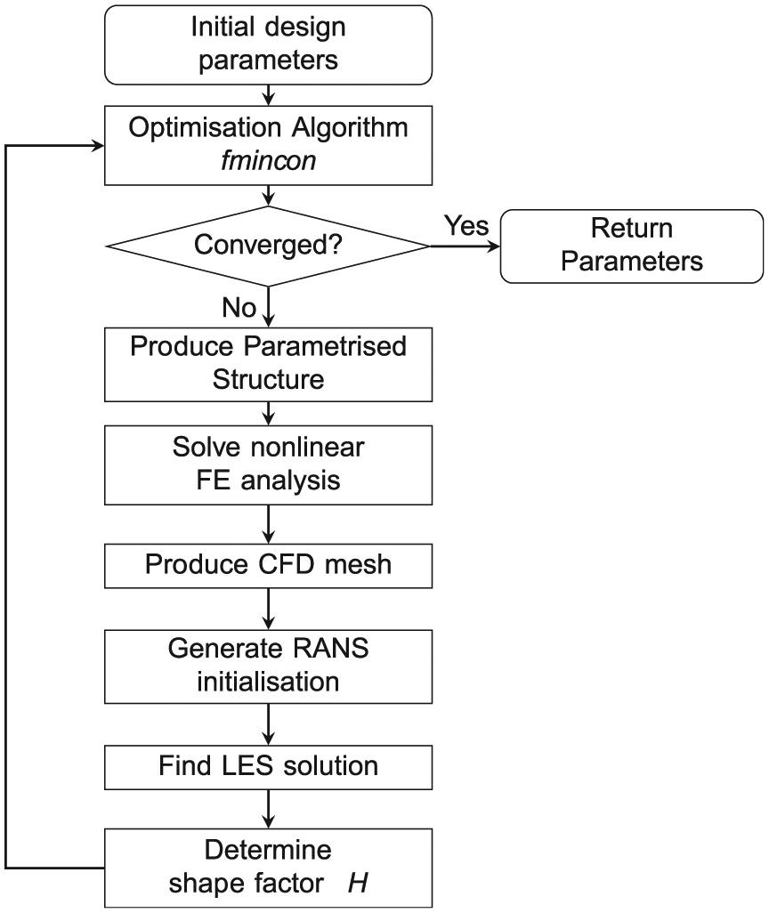
Flowchart of design optimisation process.
In this process, the design parameters, which define the surface and actuation magnitude, are selected using a constrained gradient-based optimisation algorithm. From an initial, user-selected, point in the design space an estimate of the local Hessian matrix is made using a quasi-Newton method. Once the local gradient of the objective function is known, a sequential quadratic programming SQP method is used to identify the next feasible point in the design space. In the current work, this is implemented in the function fmincon from the MATLAB Optimisation Toolbox (Mathworks Inc., 2015).
The deformed surface is then computed and the resulting geometry is used as the boundary for a computational fluid simulation. The flow field resulting from this analysis is reduced to a scalar quantity which may be used to describe separation resistance and on which the optimisation algorithm acts. Each step in this process is presented in further detail in the following sections.
Structural analysis
In order to limit the problem complexity, the structural domain is prescribed as a quadrilateral of variable size but which is symmetrical around the x-axis as shown in Figure 3. The adaptive domain is therefore described by four design variables
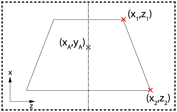
Spatial design parametrisation for an adaptive surface. The adaptive domain is defined by verticies 1 and 2 within the exterior domain (––) and is actuated at vertex A.
To calculate the deformed geometry, the commercial finite element package Abaqus version 6.13-2 (Dassault Systemes, 2013) is used. The deforming domain is discretised using a mesh of quadrilateral shell elements with six degrees of freedom at each node and linear interpolation of variables (S4). Due to the high levels of in-plane strain reported by Rhodes (2012) in his work, all analyses conducted account for geometrical nonlinearity. The coupled strain energy equations are solved using a Newton method and convergence is taken when residuals of all variables are below
The edges of the model are restrained in all degrees of freedom, maintaining continuity in both position and surface gradient with the surrounding material, as required for a compliant structure. The mesh is actuated out-of-plane through a displacement boundary condition acting perpendicular to the surface which is imposed at a chosen actuation location,
Aerodynamic analysis
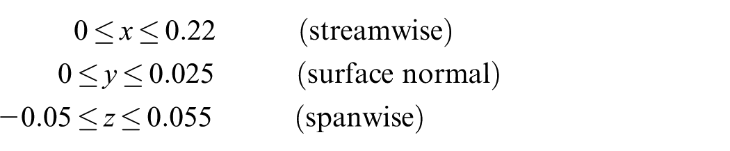
Once computed, the effect of the resulting geometry on the boundary layer is required. To accomplish this, the deformation field is incorporated into the base of structured hexahedral mesh for use in the open-source CFD toolbox OpenFOAM. To map between the nodes of the finite element solution and the required regular Cartesian spacing of the CFD mesh, a Delaunay triangulation is used to linearly interpolate the data. The fluid domain in this work represents turbulent flow over a plate and is described by the boundaries
The mesh has
In order to capture the behaviour of the separating turbulent boundary layer with sufficient accuracy, a Large Eddy Simulation (LES) has been selected. An LES provides a necessary compromise between resolving all of the turbulent structures, and their influence in the boundary layer, generated by the modified geometry and the limitation in both mesh density and simulation run-time due to the available computational capability.
The fluid simulation consists of two steps, initially a Reynolds averaged Navier–Stokes (RANS) solution is found using the Spalart–Allmaras turbulence model (Spalart and Allmaras, 1992). This simulation is used to produce an approximate result which in turn is used to initialise a LES using the Spalart–Allmaras sub-grid model. The simulation is continued until the boundary layer metric, described below, converges to a mean determined using a rolling average of 500 samples. A typical convergence plot for the objective function is given in Figure 4(a).

Typical convergence plots of the objective function. (a) Convergence of LES objective function for each subiteration call. (b) Plot of optimisation function convergence () and corresponding peak von Mises stress for nonlinear ( ) and linear (
 ) cases.
In order to improve the efficacy of the adaptive structure using optimisation it is necessary to choose a suitable metric to reduce the three dimensional data from the LES to a scalar value. The boundary layer shape factor H is the non-dimensional ratio between two measures of boundary layer thickness, displacement thickness
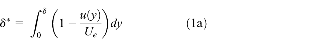
where
Optimisation with structural constraints
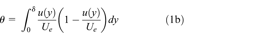
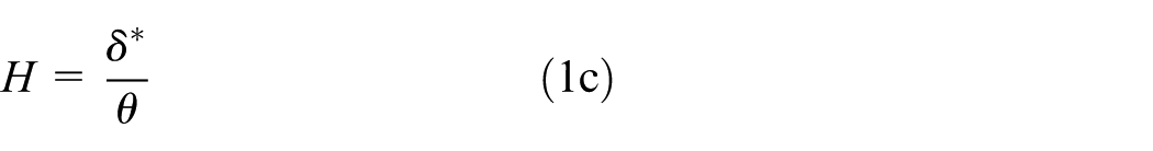
In addition to maximising the mixing effect of the adaptive device, it is also necessary to ensure that the final deformation remains elastic. This will enable the device to be retracted when not required, removing its influence on the flow in off-design conditions. To achieve this an external penalty function has been used which artificially penalises the objective function (Smith et al., 1997), by the ratio by which the yield criterion is breached multiplied by a tunable coefficient a, if the peak von Mises stress
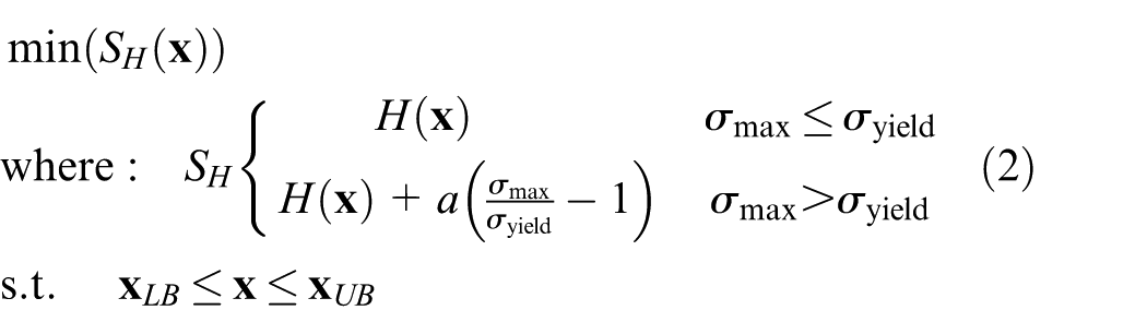
where
The area of interest for the increase in boundary layer momentum is fixed as a plane
Optimal deformation of a surface with uniform section
We first consider the case when the surface has a uniform section and thickness

where
Optimisation design variables x and their constraints xLB and xUB.
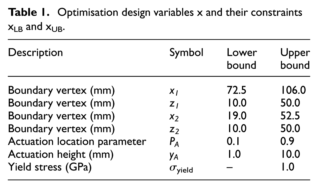
Figure 4(b) shows a rapid improvement of the shape factor during the optimisation with convergence to the identified minimum after four iterations. The peak von Mises stress within the surface is plotted alongside the shape factor. As described above, the simulations used for the objective function are geometrically nonlinear; however, the peak linear stress, negating in-plane loads, is plotted for comparison. Streamwise and spanwise sections of the final geometry are shown in Figure 5. The computed boundary layer velocity profiles are presented in Figure 6, and the associated shape factors are shown in Table 2. The results from a static forwards wedge VG of height 2 mm are also computed in the same position to provide a comparison of the values achievable without the constraints imposed by morphing.
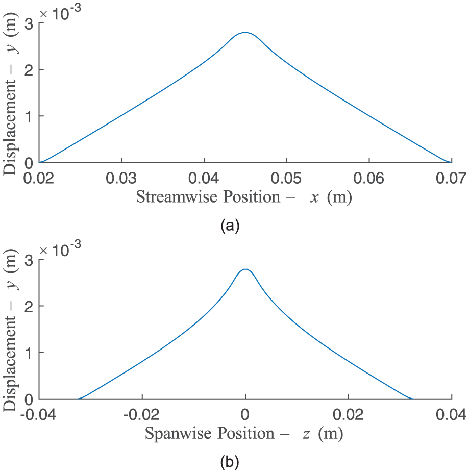
Deformed geometry resulting from the converged optimisation function using a shell section. (a)
Mean boundary layer profiles for the ‘clean’ condition (), the optimised deformation () and a fixed VG().
Comparison of boundary layer shape factors.
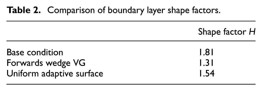
The morphed surface decreases the computed shape factor and thus increases the separation resistance of the boundary layer. However, the improvement in shape factor is only half of that achieved by the VG. In Figure 4(b) it can be seen that, as the optimisation progresses, the peak stress in the surface increases to the threshold of the penalty function at which point no further significant improvement in objective is possible. When the in-plane membrane stress is neglected, in a linear solution, a similar trend is seen but the increase is not as great and, critically, the result remains significantly below yield. It is therefore clear that the in-plane loads are acting as a significant limitation in the design space for this case.
In order to develop a solution to the problems faced in this type of adaptive surface, the geometric differences between the profile morphs described previously and a local 3D geometry change will be investigated in the following section.
The generation of membrane stress due to changes in Gaussian curvature
In the profile morphing structures developed by previous authors a large elastic out-of-plane deformation from a uniform plate is achieved through a combination of a change in curvature

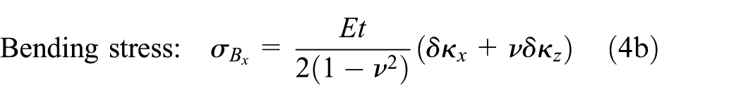
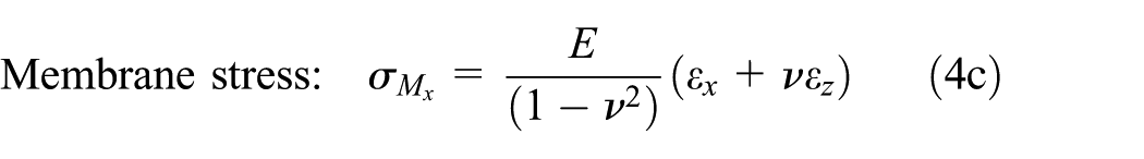
in which E is the Young’s modulus,
For any surface there exist two principle curvatures

For the special case of a shell with constant cross-section, such as a wing, while
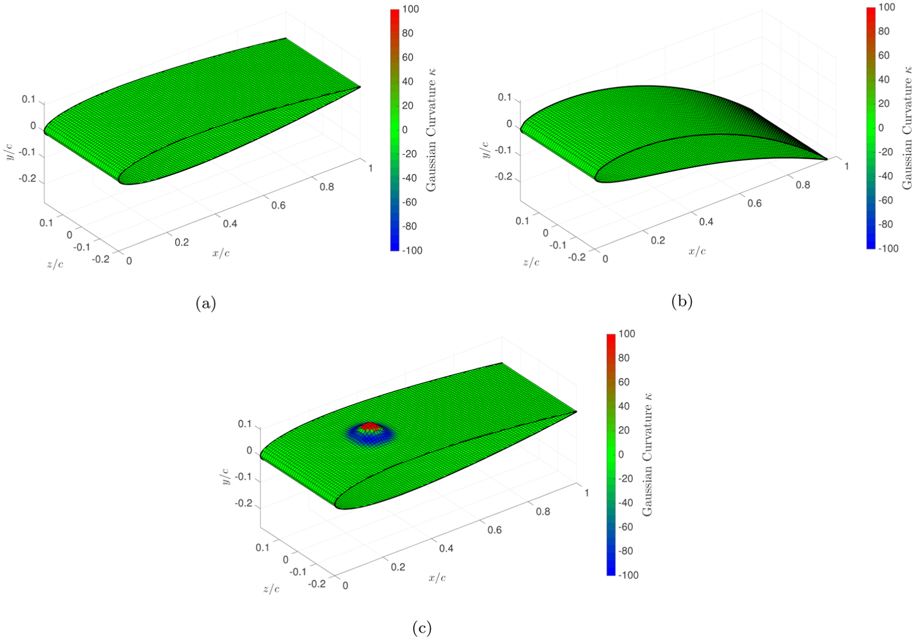
Gaussian curvature distributions on three wing segments: (a) unmodified geometry; (b) the same section following a camber variation (zero Gaussian curvature); and (c) the original section with a local, out-of-plane, geometry change (non-zero Gaussian curvature).
where
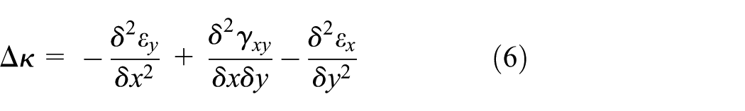
In order for an adaptive surface to generate a spanwise variation in the flow, such as that found downstream of a vortex generator, it is clear that a constant sectional change to the structure is not sufficient. Instead, in the actuated configuration, the device must be developed from the surface and yet be finite in all directions. The developed geometry must therefore also contain areas where both principle curvatures are finite and thus must result in a change in Gaussian curvature (Figure 7(c)). From equation (6) it can be seen that this must be accompanied by the generation of in-plane membrane strains. Equation (4c) shows that the resulting stresses from membrane strains do not scale with thickness, as is the case with bending stresses, and so cannot be mitigated through the selection of a thinner material. The resulting limitation depends solely on the change in arc length over the surface, and so severely constrains the achievable elastic deformation.
In addition, the maximum out-of-plane deformation will be achieved when the contribution to peak stress has the minimum possible component due to bending and this occurs as
This ‘tenting’ occurs due to the much larger levels of strain energy required to extend the material rather than reduce the curvature in order to meet the constraints. Due to the inherent coupling between material thickness and bending stiffness in a shell, the chosen parameters must be a compromise between the deformation levels required and the loss of fidelity of the original geometry. It is therefore desirable to develop a method to decouple the bending and membrane properties of the surface such that a low in-plane stiffness can co-exist with a high out-of-plane bending stiffness.
The limitation on shape change due to membrane stress has been encountered previously in profile morphing applications. In order to achieve more extreme elastic variations in cross section, dedicated anisotropic materials, such as the corrugated structures proposed by Yokozeki et al. (2006), have been used to allow elongation in one direction while maintaining high bending strength in the other. These expand the range of available profile morphs but again rely on a 2.5D geometry change. An alternative method to increase the range of available morphs, which has been demonstrated in both profile and span morphing applications, is to replace the wing skin with a two-dimensional lattice structure. These structures are formed when a unit cell of slender beams and constant height is tessellated in-plane to form a surface. Under load, the principle deformation mechanism of the structure is either the bending or stretching of the constituent spars.
In order to distinguish between these two types of lattice, Deshpande et al. (2001) proposed that the rigid joints of the structure be replaced with pin-joints and the resulting system analysed for kinematic determinacy. If this version of the lattice is kinematically determinate then the problem is stretching dominated and the membrane stress remains significant. If, however, the pin-jointed lattice is kinematically indeterminate then mechanisms, regions where displacements are possible without strain, are present. In the rigid structure the moments which cause rotations in the pin-jointed system instead cause the beams to bend, which has been shown by Gibson and Ashby (1999) to result in a similar global deformation.
An example of a bending-dominated structure is shown in Figure 8. The in-plane load, which would normally result in in-plane strain and thus be limited to a small elastic deformation, causes a moment in the nodes. As the beams are slender these bending stresses are much smaller than the equivalent membrane stresses within a stretching dominated lattice, and so a larger global elastic deformation is possible. Unlike the corrugated surface, the bending of a lattice occurs in-plane and throughout the surface allowing for deformations in both principle directions.
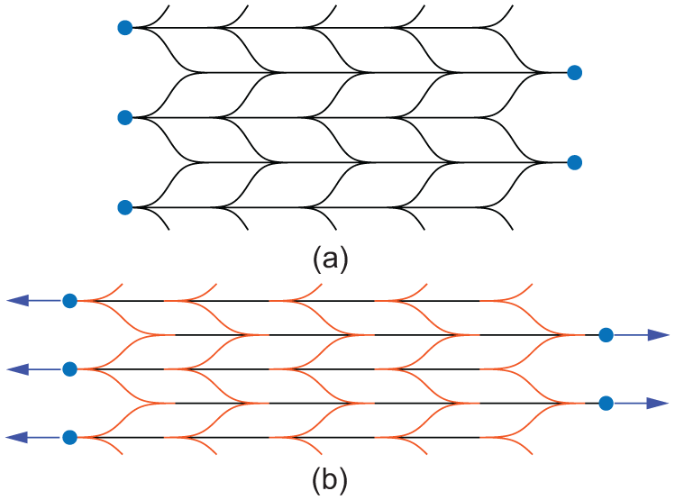
Example of a bending-dominated lattice under in-plane normal loading: (a) before deformation. (b) after deformation.
Lattice structures, with
Hex-chiral lattice surface
Referring to equations (4) and (5), for an out-of-plane deformation, the use of a negative Poisson’s ratio auxetic material reduces the stress induced in the formation of a geometry with
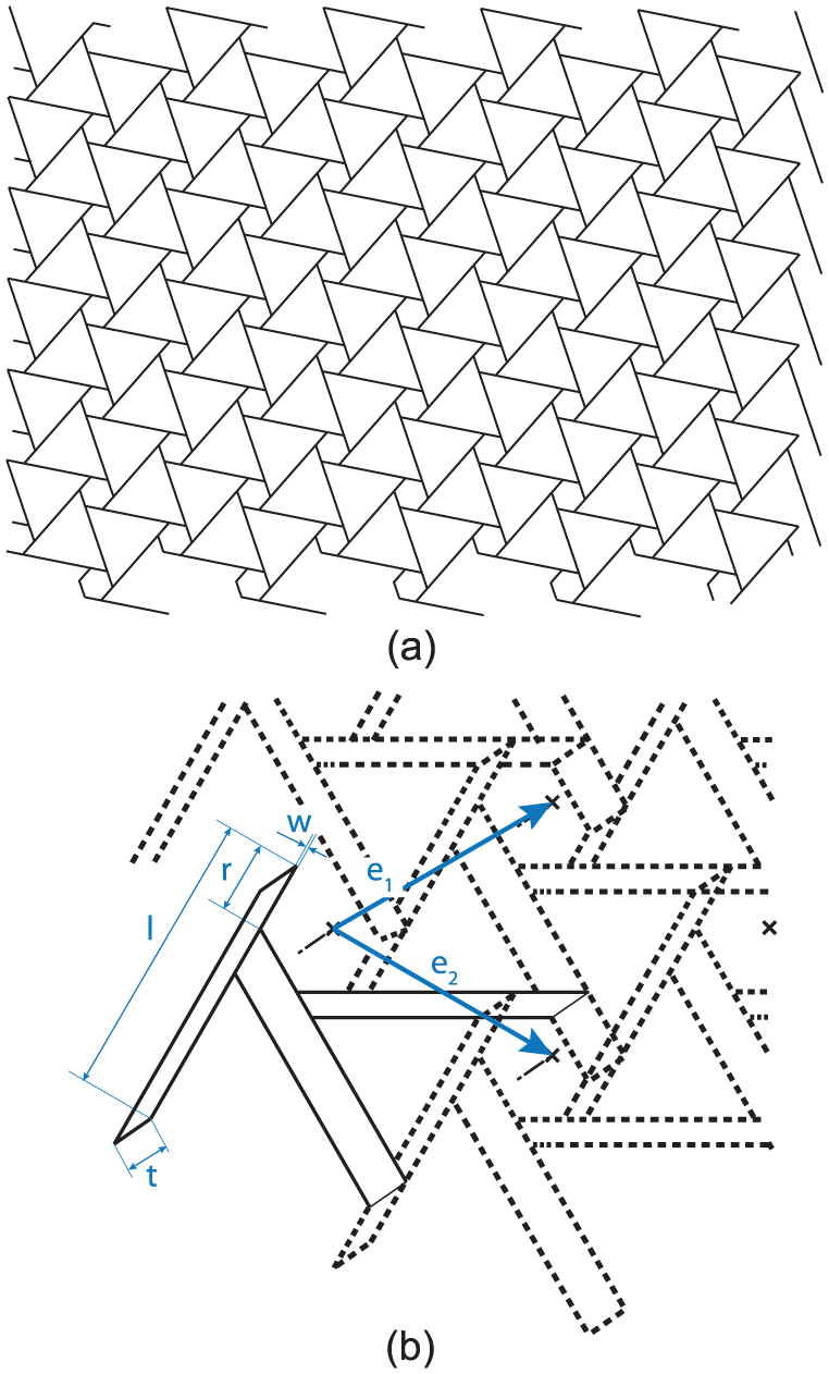
(a) 2D lattice with hex-chiral geometry, and (b) the unit-cell parameters which define the lattice.
Design parameters and constraints
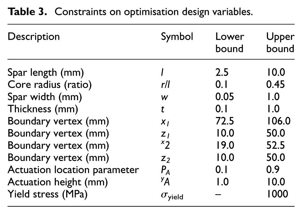
The location of boundary constraints remain design variables, as in the study above, however, additional variables are required to fully define the lattice topology and allow the adjustment of all bulk material properties during the optimisation. These parameters, shown in Figure 9(b), are spar length l, width w and node radius r. In addition, for the consideration of out-of-plane geometry change, material thickness t is an important parameter which can be varied independently of lattice topology. Additional constraints are therefore also required to bound the unit cell topology of the lattice. The bounds on cell size are predominantly determined from manufacturing limitations; however, the upper bound on core radius is determined from the limits of kinematic determinacy in the structure. At the limit
Constraints on optimisation design variables.
Structural analysis
The analysis is again conducted in Abaqus over the quadrilateral domain with design parameters described previously. The unit-cell topology is produced with Timoshenko beam elements with six degrees of freedom at each node and which capture both shear and bending deformation (B31). Each spar in the unit cell is split into seven elements, and the initial node is centered at
Optimal deformation of a lattice based surface
The optimisation was again run for a number of iterations and checked for convergence. The optimisation history shown in Figure 10 shows a rapid improvement over the initial iterations followed by limited further improvement with each subsequent iteration, indicating convergence to the identified minimum point. It can be seen that, for all iterations, the peak stress remains significantly below yield. The penalty function is therefore not constraining the design, and hence the selection of design parameters is based solely on geometry.

Plot of optimisation function convergence with shape factor () and corresponding peak von Mises stress ( ).
).
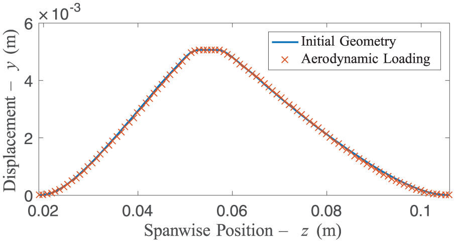
Section views of the deformed geometry are shown in Figures 11(a) and (b) alongside the shell results from the previous study. The peak deformation using a lattice based surface has increased significantly when compared to the original solution from the surface with uniform section presented previously due to the increased in-plane yield strain of the lattice structure. The increased strain is accompanied by a decreased stiffness of the aerodynamic surface. To ensure the morphed surface maintains its geometry, under the induced aerodynamic loading, the mean pressure field calculated during the simulation is applied to the deformed lattice. The mean nodal displacement due to aerodynamic loading is
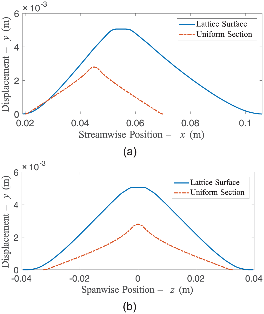
Deformed geometry resulting from the converged optimisation function. The deformation achieved with a simple shell in the previous section is included for comparison.
Mid-plane section of optimal lattice geometry under aerodynamic loading. (a) x–y section at
Experimental validation
Once the optimised design had been produced, the results were validated in separate wind tunnel and structural experiments. These elements were tested separately to ensure that unexpected influences such as manufacturing irregularities did not influence the results.
Boundary layer velocity profiles
In order to test the effect of the final geometry on the boundary layer, a static version of the surface was reproduced using a Connex Objet 350 3D printer with spatial accuracy of
Stereo particle image velocimetry (sPIV) was used to provide details of the flow field downstream of the manipulated geometry. The illuminating light sheet was produced using a Litron LDY-304 high-speed laser operating at 1 kHz. The image pairs were captured using two Phantom Miro M310 cameras at either side of the wind tunnel with Scheimpflug mounts and 135 mm objective lenses with a fixed aperture of f2.0. The results presented were processed using LaVision DaVis software using a square interrogation window size of
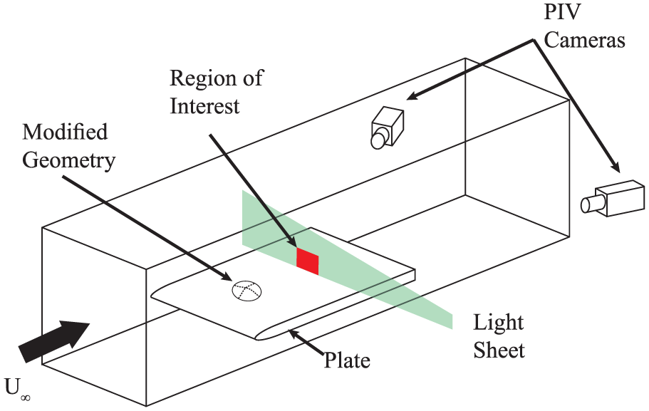
Schematic of experiment to validate the optimisation results.
The boundary layer profiles from the LES used in the optimisation process are compared to those of the ‘clean’ surface and the experimental results in Figure 14. Assuming a normally distributed measurement error, the 99% confidence intervals for the experimental velocity profiles are
Mean boundary layer profiles for the ‘clean’ condition (), with a discrete forwards wedge vortex generator () and with a representation of the optimised adaptive structure (). Experimental and computational results for all cases are shown as solid (—) and dotted (⋯) lines respectively.
From the shape factors in Table 4, it is clear that both the surface representing the adaptive geometry, and the traditional VG are effective at transporting momentum towards the wall within the boundary layer. Comparing the velocity profiles it can be seen that the discrete vortex generator is slightly better than the adaptive structure. This is to be expected as the requirement for surface and gradient continuity to accomplish an elastic adaptive structure is in direct opposition to the formation of tightly bound vortices, which requires sharp discontinuities at the device trailing edge.
Comparison of boundary layer shape factors
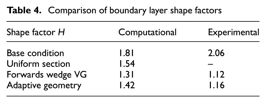
The experimental data from the base geometry agree well with the computational results, however, a small overestimation of the velocity is visible close to the wall in the CFD result. The transfer of momentum by the adaptive geometry is qualitatively captured by the LES simulation. However, the velocity discrepancy between experiment and simulation is larger with the increased surface complexity. This is believed to be due to the limitations of grid density in the LES simulation used as part of the optimisation routine. While locally increased mesh density downstream of the device could improve the result accuracy by capturing more of the small scale motion, the increased computational resource required is prohibitive. Based on both the computational and experimental results, it has been possible to produce an adaptive geometry to replace the function of a VG for transfer of momentum towards the wall in a boundary layer.
Physical model of adaptive vortex generator
Once the effect of the modified geometry on the boundary layer was validated experimentally, the parametrised lattice was manufactured from stainless alloy 1.4310 shim steel. The lattice geometry was cut from this shim using an Oxford Lasers Compact Micromachining System. The geometry was inspected under a calibrated AxioVision measurement system and Zeiss Imager.M2M microscope. The dimensional accuracy of the cut geometry was found to be within
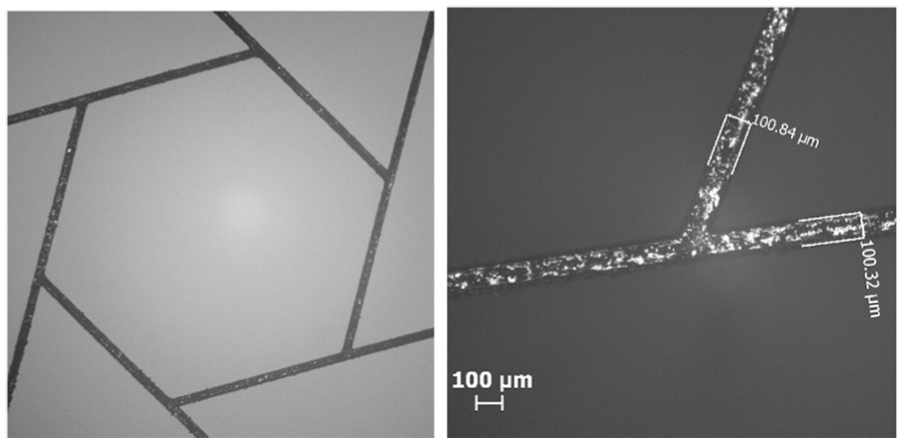
Typical node of the manufactured lattice viewed under an optical microscope.
To form an impermeable boundary, the lattice was encapsulated at the mid-plane of a 1.0 mm elastomer skin formed of EcoFlex silicone 00:50 rubber. This membrane was not included in the finite element simulation as, with a Young’s modulus
The encapsulated lattice structure is fixed to a plastic housing for measurement as shown in Figure 16(a). Actuation of the structure requires a sustained force over a large, precise, stroke. This is implemented using a Haydon Kirk G4 19000 stepper motor driven linear actuator which has a step angle of 7.5°/step and a linear travel of 12.5 μm/step. The motor is driven with a MSD415 micro-stepping motor driver which further subdivides each step into 64 increments giving a theoretical positional increment of 0.20 μm.
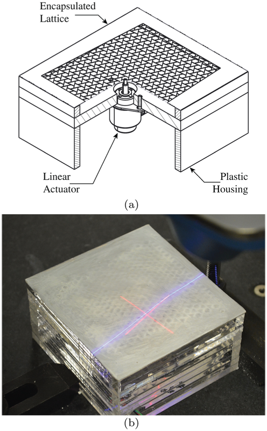
Manufactured lattice assembly. (a) Sectional view showing the encapsulated lattice and actuator assembly. (b) Deformed lattice model during laser measurement.
The surface of the encapsulated lattice was coated in a thin layer of powdered titanium dioxide and measured using a Faro measurement arm and 3D laser scanning head (Figure 16(b)) with a spatial accuracy of
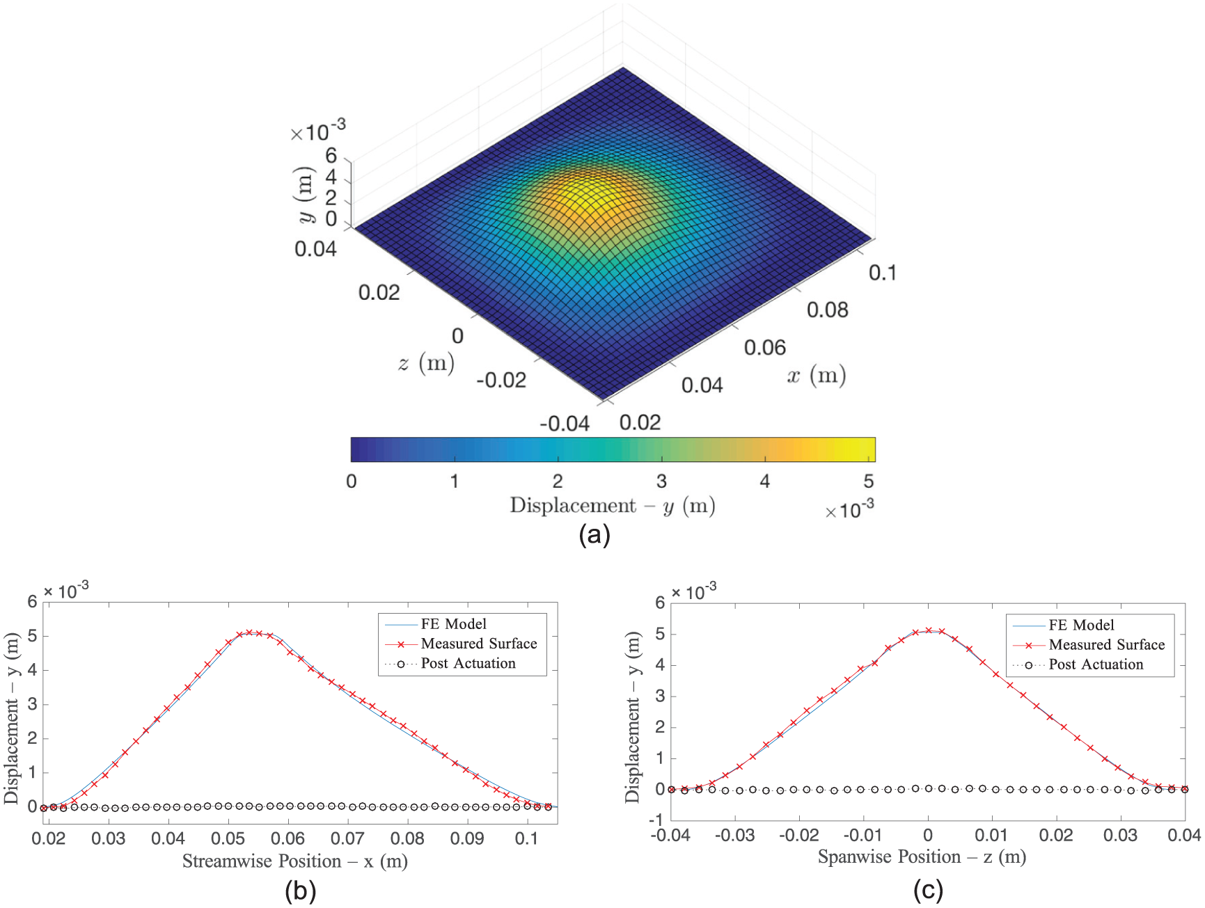
Measurement and comparison of manufactured lattice displacement to finite element predictions. (a) Measured surface deformation. (b)
Conclusion
This paper examines the production of a locally finite morph from a continuous surface of uniform section for the prevention of boundary layer separation. A gradient-based optimisation algorithm with a multidisciplinary objective function allows the identification of an optimal set of design parameters for increasing the near-wall momentum of the flow with an elastically adaptive surface. A limitation on the design space is encountered due to the rapid increase in in-plane ‘membrane’ strains. This severe constraint is attributed to the variation of the surface Gaussian curvature and hence is not seen in 2D profile geometry changes.
To overcome this issue, the use of a bending-dominated hex-chiral lattice has been proposed with Poisson’s ratio
The resulting elastic deformation geometry was replicated and tested experimentally. The adaptive structure significantly decreased the measured downstream shape factor, indicating a transfer of momentum towards the wall and so an increase in separation resistance. The downstream effects of the adaptive surface were also compared to that of a static forwards-wedge vortex generator. The static device provides better mixing than that found with the adaptive structure, and this is due to the fixed separation at discontinuities in surface gradient found on the vortex generator which are not possible with an adaptive surface.
Once the effect of the static morphed geometry was validated, the lattice was manufactured in stainless steel to the parameters resulting from the optimisation. The model was then deformed and measured using a 3D laser scanning instrument. The actuated surface compares well with the results from the FE simulation and hence the geometry used in the experimental validation conducted in the wind tunnel. Critically, the surface returned to its original position when the actuation was removed, demonstrating that the deformation was achieved elastically. It has therefore been shown that, by using an auxetic lattice structure, it is possible to produce an adaptive boundary layer control device which may deployed and retracted from an aerodynamically clean surface as required. This is an improved design as compared to traditional VGs and implies that the technique may be applied to time dependent surface changes.
Footnotes
Declaration of conflicting interests
The author(s) declared no potential conflicts of interest with respect to the research, authorship, and/or publication of this article.
Funding
The author(s) disclosed receipt of the following financial support for the research, authorship, and/or publication of this article: This work was supported by the Engineering and Physical Sciences Research Council (Grant No.: 1256485). All data created for the research presented in this paper may be accessed on request by email to