
Abstract
Introduction
Between 16%-67% of patients with chronic lateral ankle instability (CLAI) will experience secondary osteochondral lesions of the talus (OLT), which, if left untreated, will result in severe ankle degeneration and irreversible loss of ankle function. Depending on the area and depth of the talar cartilage injury, there are various treatment options such as ankle arthroscopic lesion cleanup, bone marrow stimulation, and autologous and allogeneic bone cartilage transplantation. Compared to other articular cartilage, the talar articular cartilage is thinner—similar in thickness to human periosteum. The thickness of the articular cartilage of the talar fornix is as follows: female (1.11 ± 0.28) mm; male (1.35 ± 0.22) mm, 1 while the thickness of human periosteum is about 1 mm, divided into outer layer and inner layer, with abundant blood vessels and nerves, and contains osteoblasts, which play a key role in bone healing. At present, the International Cartilage Repair Society (ICRS) guidelines believe that the talar cartilage injurys of stage III to V with lesion area >1.0 cm and depth >0.5 cm requires the use of autologous osteochondral transplantation (AOT), 2 for treatment because it has a higher repair success rate (52%-92%).3,4 The application of autologous bone grafting of iliac bone with periosteum for the treatment of cartilage injuries of the talus is one of the important methods.5–7 The reasons for this are: iliac bone extraction does not damage articular cartilage, a large amount of bone can be taken to repair large and deep talar lesions, and the periosteum on the surface of the iliac bone can be transformed into fibrocartilage of the talus to achieve a relatively satisfactory repair effect on the damaged talar cartilage. However, the anatomical morphology of the ilium and the talus are different, and the current iliac bone extraction is only based on experience, which is prone to mismatch between the implanted ilium and the talar dome joint, and even to complications such as postoperative traumatic arthritis, which affects the clinical efficacy. Especially in the case of the talus (dome) shoulder lesion, it will be more difficult to achieve multi-planar matching of the periosteal iliac and talar lesions.
This study utilizes the rapidly developing Digital Orthopaedics technology (Digital Orthopaedics) to carry out research on Iliac-Talar Grafts. Digital orthopedics technology is a new technology developed in this century to realize accurate and digital surgical design and operation. It integrates computer-aided design/computer-aided manufacturing (CAD/CAM) and rapid Rapid prototype (RP) as a whole.8,9 Virtual surgery planning and precise intraoperative operations with the help of digital three-dimensional models and surgical templates have the advantages of improving accuracy and shortening the operation time.10,11 This study utilized computer-aided design to reconstruct three-dimensional images of the ilium and calcaneus based on CT cross-sectional data. This approach allows for the observation of pathological sites from various angles, significantly enhancing physicians’ ability to identify complex morphologies. 12 Moreover, precise three-dimensional matching calculations can be performed, with higher accuracy compared to matching based solely on solid models.
Chromatography analysis can make quantitative and accurate judgments on the accuracy of model formation and positioning in virtual surgery, for example, chromatography can be used to analyze the matching degree of the iliac bone with the talus (dome) shoulder (Figure 1). Using CT image data to design a personalized surgical guide that meets the patient’s, it can accurately locate the intraoperative point, line position, direction and depth, and achieve precise positioning. In this study, digital orthopedics technology was used to focus on defining the bone extraction area of the Iliac-Talar Grafts required for the multi-planar lesion area on the talus (dome) shoulder lesion, and virtual surgery was performed. We assume that the best Iliac-Talar Grafts can be obtained with the aid of chromatographic cloud image analysis. However, simply finding the matching area of the iliac bone and the talus cannot accurately obtain the direction and position of the required bone during the operation. The use of personalized surgical guides can accurately locate and cut out the most matching iliac bone, and at the same time make the iliac bone removal more accurate, and finally get the best-matched Iliac-Talar Grafts for the ankle joint. Chromatographic cloud image analysis is used to study the schematic diagram of the matching degree of the talus and iliac bone. According to the color scale on the left, the lighter the color indicates the smaller the deviation between the iliac bone and the talus, and the darker the color indicates the greater the deviation between the iliac bone and the talus.
Materials and methods
Materials
A total of twenty-two cases with both talar CT data and iliac CT data were collected from January 2019 to June 2023, one case each of talar deformity injury and bone disease were excluded, resulting in a selection of 20 cases. There were 11 males and 9 females, age: 39.5 ± 12.2 years old. And number the patients in order (1-20). 3D printer Objet Connex350™; Stratasys Ltd, Eden Prairie, MN, USA Med30 medical translucent photosensitive resin material, USA 128-slice helical CT scanner Siemens definition AS, Germany, set the scanning layer thickness to 0.8 mm and the pitch 1.0 Minics15.0 image processing software Belgium Materialise Magics20 software Belgium
Method
Iliac bone and talus separation and three-dimensional reconstruction
All patients received CT examination of the ipsilateral ankle joint and iliac bone (CT scan parameters: 140 kV, slice thickness of 0.8 mm, scan time of less than 20s).
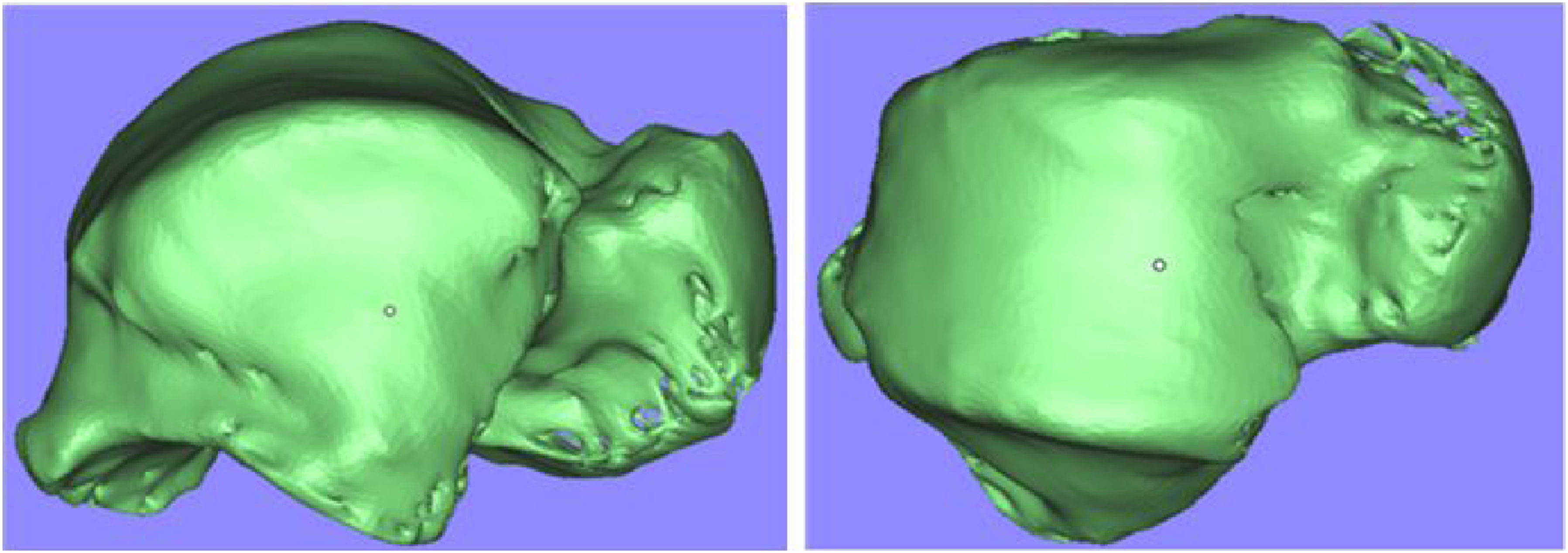
The original two-dimensional image data of the ankle joint must be transferred to Minics15.0 (Materialise, Leuven, Belgium) image processing software in DICOM format (Figure 2). This will result in the formation of a three-dimensional image of the ankle joint, which will then be used to separate the talus (Figure 3). The iliac bone can then be separated by the same method, and the STL (Stereo Lithography) file format of the iliac bone and the talus can be generated. Import image data into MIMICS image processing software and perform 3D reconstruction. Separate the three-dimensional model of the ankle joint and select the required talus. Top, front, and oblique views of the target repair area of the medial talar lesion. The red area indicates the target repair area on the medial top of the talus and the medial wall. The black line indicates that the diameter of the target repair area is 1 cm.

The establishment of a model for simulating internal and external osteochondral injury of the talus
The iliac and talar STL file data were imported into Magics software (Materialise Ltd, Leuven, Belgium). A cylinder with a diameter of 1 cm and a height of 1 cm at the medial vertex of the talus was proposed as the medial talar cartilage injury lesion (the medial target repair area), including the corresponding inner wall, two-thirds of the cartilage area was used as the top of the talus for the corresponding medial target repair area (Figure 4).
In the same way, a cylinder with a diameter of 1 cm and a height of 1 cm at the lateral apex of the talus was drawn as the cartilage injury lesion of the lateral talus (lateral target repair area), including the corresponding lateral wall, and two-thirds of the cartilage area was used as the top of the talus for the corresponding lateral target repair area (Figure 5). Top, front, and oblique views of the target restoration area of the lateral talar lesion. The red area indicates the target repair area on the lateral top of the talus and the lateral wall. The black line indicates that the diameter of the target repair area is 1 cm.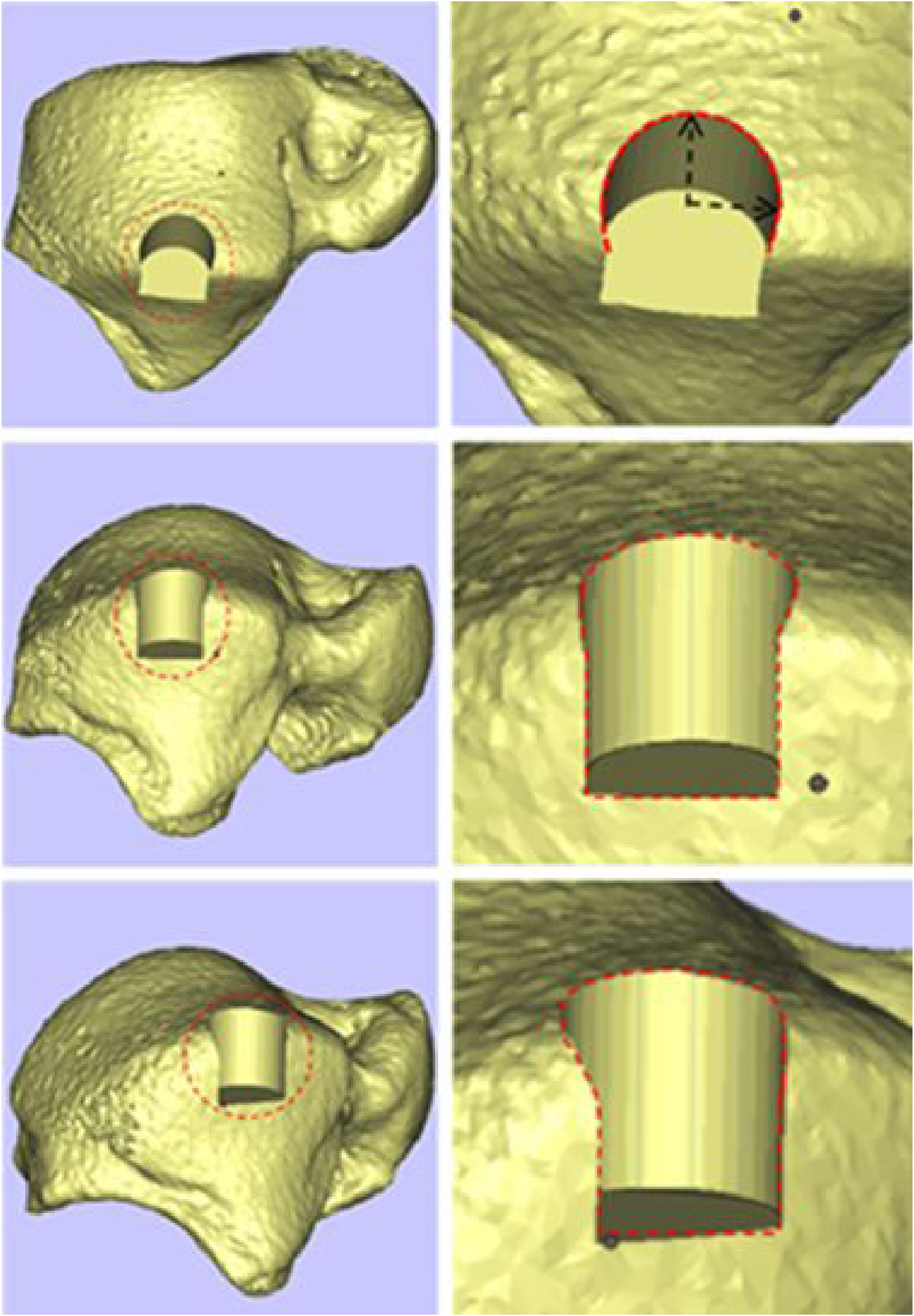
Virtual surgery
In virtual surgery, the three-dimensional image of the patient’s iliac bone is superimposed on the target repair area of the talus, the head of the talus corresponds to the anterior superior iliac bone spine, and the three-dimensional contour of the iliac is superimposed with the three-dimensional contour of the target repair area of the talus to make the iliac bone transparent. Compare and observe the overlapped part of the target repair area of the inner and outer talus and the iliac bone (Figure 6). (a) Schematic diagram of fitting between the target repair area of the medial talus (dome) shoulder lesion and the medial iliac bone. The red area is the target repair area on the medial top of the talar. The diameter of the target repair area is 1 cm. (b) Schematic diagram of fitting between the target repair area of the lateral talus (dome) shoulder lesion and the lateral iliac bone. The red area is the target restoration area at the top of the lateral talus. The diameter of the target repair area is 1 cm.
Iliac-talar grafts matching to injury lesions
The iliac bone restoration used to repair the medial talar cartilage injury was virtually resected, and the medial talar cartilage injury lesion was also virtually resected, and then the two were subjected to perform multi-faceted shape fitting. See the morphological matching of the two (Figure 7), In the same way, the iliac restorations used to repair the cartilage damage of the lateral talus and the lesions of the cartilage damage of the lateral talus are virtually excised, and then multi-faceted morphological fitting is performed, and the morphology of the two is highly matched (Figure 8). (a) side view, top view, and front view of the model bone removed from the target repair area of the medial talar lesion; (b) side view, top view, and front view of the model bone removed from the medial side of the iliac bone. (c and d) Side view, top view, and front view schematic diagrams of the coincidence and matching of the target repair area model bone block for the medial talar lesion and the medial iliac model bone; shape matching. (a) Side view, top view, and front view of the model bone removed from the target repair area of the lateral talar lesion; (b) side view, top view, and front view of the model bone removed from the outside of the iliac bone. (c and d) side view, top view, and front view schematic diagram of the overlap between the target repair area model bone block of the lateral talar lesion and the lateral model bone block of the iliac bone; the schematic diagram of the fitting diagram of the iliac-talar prosthesis implanted in the lateral talus restoration area. The yellow area is the repair area on the top of the lateral talus, and the shape of the two is highly matched.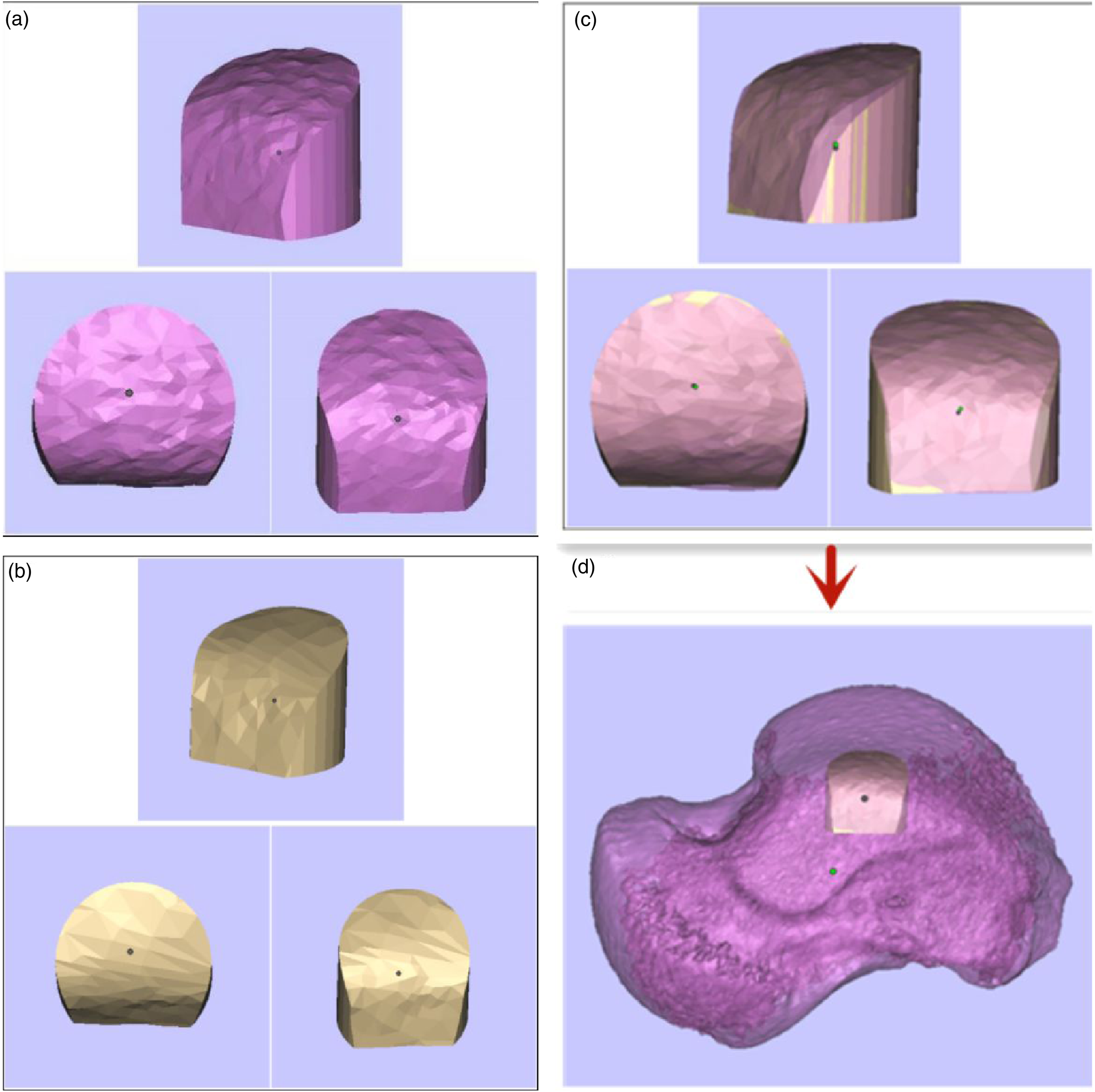

Evaluation of the accuracy of iliac-talar morphology and positioning by three-dimensional chromatographic deviation analysis
Three-dimensional chromatographic deviation analysis: Different colors represent the point cloud gap between the talus and the iliac graft after three-dimensional CT registration. The color scale varies from dark red to dark blue, and is divided into 15 levels.
Use the color depth of the overlapping part as a ruler to display and measure the bone graft fitting deviation between the resultant and the virtual surgery (Figure 9), Dark red and dark blue respectively indicate that the matching error is greater than 2 mm, and green indicates that the matching error is the smallest. If the fitting error is less than 1 mm, it is considered that the fitting meets the joint surgery standard and the fitting is accurate. If the error is greater than 1 mm, we consider that the fitting is incorrect, and we will return to the Magics software to perform the fitting comparison of the iliac and the medial or lateral target repair area of the talar until the fitting is accurate, then record the above data. Verify the degree of matching for the iliac-talar restorations in the medial target repair area (a) and the lateral target repair area (b) of the talus; the left side is the color scale ruler. The color closer to the middle of the color scale ruler indicates that the implanted iliac bone has a smaller matching deviation with the talus, and the colors at both ends of the ruler indicate that the implanted iliac bone has a greater matching deviation with the talus. Take whether it is less than 1 mm as the fitting standard limit. It can be seen from the figure that the error between the target restoration area on the lateral side of the talus and the iliac-talar restoration is smaller, and the matching degree is higher.
Positioning of the iliac bone removal area
If the fitting error between the iliac restoration and the talar lesion is less than 1 mm, the position of the iliac bone is considered the patient’s best iliac bone removal position (Figure 10) and recorded. (a) Schematic diagram of the location, shape and size of bone removal on the medial side of the iliac bone; (b) schematic diagram of the location and shape and size of the bone removal on the lateral side of the iliac bone.
Mark the valgus crest of the iliac bone in the three-dimensional image, find the highest vertex of the valgus crest (VVC), and mark the point on the iliac crest corresponding to the highest vertex. This study defines this point as Valgus-iliac crest Point (VICP) (Figure 11). Schematic diagram of the highest vertex of the valgus cristae and the valgus-iliac crest point. a is the highest vertex of the iliac valgus ridge; point 
Record the distance from the anterior superior iliac spine and Valgus-iliac crest point (VICP) to the corresponding iliac bone removal position of the medial talar lesion repair area in each patient, and the distance from the corresponding iliac bone removal position of the lateral talar target repair area to the Valgus-iliac crest point (VICP). Two sets of data are obtained. These data can accurately locate the best fitting area on the medial iliac bone corresponding to the target repair area on the medial side of the talus, and the best fitting area on the lateral iliac bone corresponding to the target repair area on the lateral side of the talus.
During the research, we found that the target repair area on the medial side of the talus and the anterior iliac crest (AIC) have a higher degree of agreement.; the target repair area on the lateral side of the talus and the posterior iliac crest (PIC) have a higher degree of agreement.
Printing of iliac and talar cutting guide
Simply finding the fitting area between the talar repair area and the iliac bone cannot accurately determine the direction and location of bone removal during surgery. To accurately locate the best-fitting iliac bone during surgery, import the iliac bone STL file into the bone defect, reconstruct the bone model by simulating the cutting, rotation, and positioning of the bone segment, and compare the preoperative model with the postoperative model, use the overlapped iliac bone osteotomy surface to create the bone guide plate.
The guide model is saved as an STL file to assist in the forming process. The same method is used to generate the STL file of the talus guide plate for guidance. Subsequently, the preoperative STL files of the talus and iliac bone, along with the STL files of the talus and iliac bone removal guide, were transferred to the Geomagice Studio software for designing the model of the talus and iliac bone removal guide.
The thickness of the 1 mm trephine needs to be considered in the design. The model is printed according to the planned size (usually printed at a 1:1 ratio), using a 3D printer (Objet Connex350™; Stratasys Ltd, Eden Prairie, MN, USA) to operate (Figure 12), using medical photosensitive resin materials to print talar and iliac bone models as well as corresponding bone guide plates (Figures 13–15). The 3D printer printing process on the bone model and the solid model of the bone guide plate. 3-D printed solid model (a) From top to bottom, the body of the talus, the bone guide plate from the outside of the talus, and the bone guide plate from the inside of the talus are taken from top to bottom; (b) From top to bottom, the body of the iliac bone, the bone guide plate from the outside of the iliac bone, and the bone guide plate from the inside of the iliac bone. (a) Take the bone guide plate from the medial side and install it in the repaired area on the medial side of the talus; (b) 3D print the solid model; (c) The bone guide plate from the inside of the iliac bone is installed on the inside of the iliac bone; (d) 3D printed solid model (18D). (a) The lateral bone guide plate is taken and installed in the area to be repaired on the lateral side of the talus; (b) 3D printed solid model; (c) The lateral bone guide plate is installed on the lateral side of the iliac bone; (d) 3D printed solid model.


Results
Distance of the fitted point of the medial target restoration area from the anterior superior iliac spine and valgus-iliac crest point (VICP).

Distance of the fitted point of the lateral target repair area from the valgus-iliac crest point (VICP).

The two areas on the iliac bone are shown in Figure 16 The use of the bone removal guide plate can achieve the accurate direction of iliac bone removal. This ensures that the fitting error of the iliac-talar restoration on the solid model and the target restoration area on the top of the talus can be controlled within 1 mm compared to virtual surgery. The optimal bone removal area for the medial and lateral iliac bone corresponding to the medial and lateral target repair areas of the talus; The blue dotted area represents the best target repair area of the lateral talus corresponding to the bone removal area of the lateral iliac bone; The red dashed area represents the best medial target repair area of the talus corresponding to the bone removal area of the medial iliac bone.
Discussion
Flick et al. found that the instability of the lateral ankle joint is an important factor for secondary talar cartilage injury.13,14 Osteochondral lesions of the talus may occur in up to 50% of acute ankle sprains and fractures, and 16%-67% of patients lateral lateral with chronic lateral ankle instability (CLAI) have secondary talar cartilage injury.13,15,16 Talar cartilage is the third most common osteochondral lesion after knees and elbows. The choice of treatment options must also consider factors such as the patient’s age, nature of work, sports needs, and extent of cartilage damage. For early talar cartilage injury, nonoperative treatment can achieve ideal results, including non-steroidal anti-inflammatory drugs, opioids, intra-ankle injections, and the application of ankle orthoses.17,18 Intra-articular hyaluronic acid injection has become an important option for the treatment of ankle osteoarthritis, but its effectiveness is controversial. 19 Steroid drugs have pain relief and anti-inflammatory effects for a long time. 20 PRP and mesenchymal stem cells have recently garnered widespread attention as a biological treatment for talar cartilage lesions, but their efficacy requires further study. 21 For advanced talar cartilage injury, surgery can achieve better clinical results. Surgical options include arthroscopic debridement of the ankle, bone marrow stimulation, supra-ankle osteotomy (SMO), traction arthroplasty, ankle fusion, and total ankle replacement surgery, autologous and allogeneic osteochondral transplantation, autologous chondrocyte transplantation and other surgical methods. Ankle arthroscopic joint debridement combined with bone marrow stimulation is currently the most widely used treatment method, and this method should only be used for lesions with a diameter less than 1.0 cm. The latest guidelines from the International Cartilage Repair Society (ICRS) in 2018 proposed that for patients with talar cartilage lesions with the lesion area> 1.0 cm and depth> 0.5 cm, autologous bone transplantation can achieve better clinical outcomes. First of all, the implanted autologous bone is easier to vascularize and integrate with the host bone. Compared with the fibrocartilage generated by arthroscopic debridement combined with bone marrow stimulation, autologous bone transplantation has advantages in restoring hyaline cartilage. 22 Secondly, compared with ankle fusion, autologous bone grafting can make the patient’s ankle mobility better and also better quality of life. The knee joint can achieve simultaneous bone and cartilage transplantation. Autologous knee articular cartilage transplantation is one of the treatment options for this type of disease. However, the articular surface curvature, thickness, and biomechanical properties of knee cartilage and talar cartilage are different, in addition, some patients with talar cartilage injuries have degenerative changes in the knee joint, the quality of the cartilage in the knee joint itself is poor. The osteochondral removal through the knee joint can easily lead to aggravation of the original knee joint symptoms,23,24 and there will be knee joint damage and the risk of pain arises, so the knee joint is not an ideal donor site. 25
The iliac bone has unique advantages as a graft source. The iliac bone is rich in red bone marrow, which is the source of regenerative cells required for angiogenesis, optimal bone formation and healing. The periosteum covering the surface of the iliac bone can transform into cartilage. The periosteum of the bone-periosteal graft is closely integrated with the iliac bone at the base, addressing the issue of potential delamination between the knee joint cartilage and the subchondral bone. The iliac bone is relatively superficial, and the technique for removing it is simple and mature. Larger and deeper talar cartilage injuries require more bone to be implanted for repair, and the amount of bone that can be taken from the knee joint is much less than that from the iliac bone. Large amounts of osteochondral bone removal of the knee joint may involve the cartilage in the weight-bearing area of the knee joint, resulting in knee joint pain and adhesions and other complications, of course, iliac bone removal still has to avoid donor site complications. 26 In the research on repairing talar cartilage damage using iliac bone grafts, Tatsuya et al. proposed the use of vascularized iliac bone graft to treat talar cartilage disease, because vascularized bone graft is not easily absorbed, has good mechanical strength and osteoinductive effect. 27 Andre et al. proposed the use of a periosteum-covered bone graft harvested from the iliac crest and grafted to the site of a talar cartilage lesion to treat severe or recurrent talar cartilage injuries. 28 Jorg et al. used iliac bone grafting combined with matrix-associated autologous chondrocyte transplantation (MACT) to treat talar cartilage lesions. 29 Martin et al. reported the application of autologous iliac bone grafting combined with a type I/III collagen matrix to treat recurrent talar cartilage lesions. Follow-up revealed that the patient’s symptoms had significantly improved. 30 Although these methods have achieved certain clinical effects, the anatomical morphology of the iliac bone and the talus are different. At present, the removal of the iliac bone is mainly based on experience. It cannot be guaranteed that the surface of the iliac bone will match that of the talus. It is very easy to appear that the shape of the implanted bone block does not match the shape of the articular surface of the talar vault, resulting in increased wear of the tibiotalar joint. Smoothing the articular surface is the basic requirement for treating intra-articular diseases. For the surgeon, it is difficult to accurately obtain the iliac bone that matches the shape of the talar cartilage injury based on experience, especially for Hepple type V talar cartilage injury, the top and side walls can be affected at the same time, it will be more difficult to accurately match the multi-planar iliac bone with the talus.
In this study, the vertex of the valgus crest (VVC) was found on the three-dimensional image of the iliac bone, and the corresponding iliac crest point was located, which was defined as the valgus-iliac crest point (VICP), and the best iliac bone extraction point was recorded to the distance between the anterior superior iliac spine and the valgus-iliac crest point (VICP). Record the distance from the best iliac bone extraction point to the anterior superior iliac spine and the valgus-iliac crest point (VICP). By proposing the anatomical site of VICP, it is helpful to describe the location of iliac bone removal more accurately, thereby facilitating precise positioning of the bone harvest area, guiding clinical accurate bone harvest, and avoiding the current uncertainty of the location of iliac bone harvest. There are two key points in virtual surgery: (1) Accurately judging whether the iliac bone graft body matches the shape of the talar lesion; (2) Determining the respective positions of the iliac bone graft to repair the medial and lateral talar lesions on the iliac bone. Through the positioning of the optimal iliac bone extraction position, CT data is utilised to design a personalised surgical guide that meets the patient’s anatomical and surgical requirements, and the surgical guide is printed out by a 3D printer to ensure that the guide and the iliac bone are perfectly matched, with cutting holes in the guide for the iliac bone implant, so that during the operation, the guide can be placed on the iliac bone in a snug fit merely to ensure that the position and direction of the bone extraction are in line with the pre-surgical plan, thereby minimising the number of human errors in operation, enhancing the surgical precision, and reducing the surgical time.31,32
At this stage, surgical guides are mostly used in oral surgery, spine surgery, and bone tumor resection,33,34 but there are no reports in the field of osteochondral repair. The thickness of the iliac periosteum is similar to that of the talar cartilage. This similarity facilitates digital orthopedic virtual surgery based on CT data, three-dimensional chromatographic deviation analysis, and guide design. The guide plate printing material is medically photosensitive resin, which has been proven to be safe for use in the human body. 35
Strengths of this study: Giant cystic lesions of the talus, particularly at the talar shoulder, are one of the major challenges in foot and ankle disease and have not been well addressed. In this study, we utilized virtual surgery in digital orthopedics, three-dimensional chromatographic deviation analys is, and guide plate technology to achieve optimal matching of the implant while preserving the periosteum on the top and side of the iliac implant. This approach has the potential to stimulate the formation of articular cartilage-like tissues, offering a novel option for treating large lesions in the shoulder of the talus. Limitations of this study:This study has only limited measurement data from Chinese individuals. A larger sample size and a diverse range of ethnicities are required for statistical analyses to achieve more accurate results. The study utilized CT and digital orthopedic techniques for analysis, and a bone extraction guide was designed. However, clinical procedures are necessary to validate it and make improvements.
Conclusion
This research applies digital orthopedics virtual surgery, three-dimensional chromatographic deviation analysis and other technologies. It proposes the anatomical site of the valgus-iliac crest point (VICP). The use of virtual surgery and three-dimensional chromatographic deviation analysis can accurately position the multi-planar lesions of the talus involving the top and sidewalls and the optimal iliac bone removal area, and find the iliac bone graft on the iliac that matches the shape of the talar lesion location, VICP helps to quantify the description of the iliac bone removal area, and is conducive to intraoperative positioning. The guide plate technique helps to accurately locate the iliac bone graft during the operation. This study provides a new plan for cutting the iliac bone graft that matches the multi-faceted talar lesion to be repaired.
Footnotes
Author contributions
Xh-G designed the study, QZ implemented the research and collected the data for the paper, as well as wrote the paper. Zh-Z analyzed the data. All authors read and approved the final manuscript.
Declaration of conflicting interests
The author(s) declared no potential conflicts of interest with respect to the research, authorship, and/or publication of this article.
Funding
The author(s) disclosed receipt of the following financial support for the research, authorship, and/or publication of this article: This work was supported by the Medical Health Science and Technology Project of Zhejiang Provincial Health Commission; 2022ZH025; 2024XY208.
Ethical statement
Data availability statement
The research data is authentic and verifiable. The datasets used and analysed during the present study are available from the corresponding author on reasonable request.