
Abstract
Introduction
Calcaneal fracture is a common foot injury that accounts for 60% of tarsal bone fractures; 75% of calcaneal fractures involve subtalar joint damage.1-4 Open reduction internal fixation (ORIF) is the gold standard of treatment for calcaneal fracture combined with subtalar injury. 5 It is often crucial to use sustentaculum Tali (ST) screw fixation in calcaneal fractures to secure the posterior talar articular surface (PTAS). According to previous researches, using ST screw fixation in calcaneal fractures had three major advantages: First, maintaining a firm and stable reduction of PTAS 6 ; Second, dispersing the interaction force among fracture pieces to prevent displacement 7 ; Third, avoiding the complication of` hindfoot varus. 8 Therefore, how to place a screw into the ST has become an important topic in calcaneal fracture research.
Placing screws precisely into the ST is always a challenge for surgeons; there are three reasons: First, the size of ST is much smaller than that of the calcaneus. Second, there is a certain distance from the screw entry point to the ST. Thus, small differences in the starting angle could lead to large deviations of the landing point. Third, ST often remains unexposed in common surgical approaches of calcaneal fractures surgery. Therefore, some surgeons prefer using a Screw Targeting Clamp to assist with ST screw placement. However, according to some researches, Screw Targeting Clamp did not show more benefits than the freehand technique; instead, it was more of a training device for inexperienced surgeons.1,9
When it comes to ST screw placement, the freehand technique is always an important issue. Studies indicated that there is only 60% accuracy to use a freehand technique for ST screw placement, since it mainly depends on the surgeon’s experience. 10 Empirical methods may increase the risk of screw breaching into the subtalar joint and would be likely to cause damage to adjacent tendons and neurovascular structures. 6 To improve the accuracy of ST screw placement, we need to better understand ST anatomy and the parameters of successful screw placement. Therefore, we retrospectively analyzed CT scans of 110 feet to measure the anatomical parameters of successful ST screw placement, such as the entry point, starting angles, and length of the trajectory.
Method
We collected 230 unilateral foot CT scans performed between January 2018 and December 2019 from our institution. One hundred and twenty cases were excluded due to deformity, fracture, arthritis, or tumor in the foot. The remaining 110 scans included 85 left feet and 25 right feet, 37 females, and 73 males, and the average age was 37 (range: 18–50) years. All CT scans were performed using US GE 16-slice spiral CT. The 3 D reconstruction of the calcaneus used Mimics Research-19.0. An electronic digital caliper and a goniometer were used for cadaveric measurements.
Anatomical measurements of ST
The definition of anatomical landmarks were shown in Figure 1.
11
As shown in Figure 1, the heights of ST in the posterior, middle, and anterior sections were defined as af, be, and cd, respectively. Also, the width of ST was defined as W. As shown in Figure 1 (b), ST was cut from the calcaneus by Mimics Research 19.0. The volumes of ST and calcaneus (ST excluded) were measured, and the average ratio of two volumes was also calculated. Anatomical landmarks in medial view (A) and superior view (B) of the left calcaneus. a. The most posteroinferior point of ST, b. The most medial point of the lower edge of ST, c. The most anteroinferior point of ST, d. The most anterosuperior point of ST, e. The most medial point of middle talar articular surface (MTAS), f. The most posterosuperior point of ST, W. The width of ST.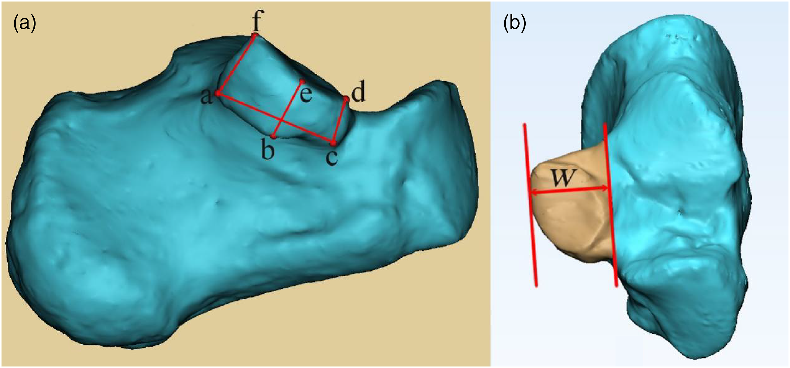
Simulation of ST screw placement
The center of the cut ST was calculated by Mimics Research 19.0. A 4-mm-diameter ST screw passed the ST center and was placed into the medial aspect of ST, starting from the lateral wall of PTAS (Figure 2). The criteria for successful ST screw placement were as follows: First, adjacent anatomical structures remain intact after ST screw placement, including MTAS, PTAS, medial wall of the calcaneus, and calcaneal sulcus; Second, the screw trajectory should generally pass below PTAS, calcaneal sulcus, MTAS, pass the ST center, and stop at the middle of ST. Lateral view (A) and superior view (B) of the left calcaneus. 1. ST, 2. Calcaneus (ST excluded), 3. ST screw, G. The ST center (Green point). The ST screw passed the ST center and was placed into the middle of ST, starting from the lateral wall of PTAS.
Establishment of 3D coordinate system
We established a 3 D coordinate system to measure the angles of successfully placed ST screws. The foot’s longitudinal axis was taken to lie along a line connecting a marker on the posterior distal end of the calcaneus to one on the dorsal foot between the heads of the second and third metatarsals. The longitudinal axis of the foot was defined as the y-axis. In the 3 D coordinate system, the original point (I point) locates at the mid-point of the line segment (the axis of the foot in calcaneus). The sagittal plane consisted of the y-axis and the highest point in calcaneal tuberosity (H point). The x-axis and z-axis were calculated with 3-Matic Research 11.0, according to the sagittal plane, the I point, and the y-axis. Eventually, a 3 D coordinate system was established as shown in Figure 3. Lateral view (A), anterior view (B), and superior view (C) of the left calcaneus. H. The highest point of calcaneal tuberosity (red point), I. The original point: the mid-point of the line segment (the foot’s axis in calcaneus), x. x-axis, y. y-axis (the longitudinal axis of the foot), z. z-axis.
The angles and length of ST screw trajectory
The angles were calculated according to the x-axis, y-axis, and z-axis. X angle, Y angle, and Z angle defined the angle between ST screw and x-axis, the angle between ST screw and y-axis, and the angle between ST screw and z-axis, respectively (Figure 4). We also measured the length of ST screws. Superior view (left) and anterior view (right) of the left calcaneus. 1. Y angle, 2. X angle, 3. Z angle, G. The center of ST, I. The original point, x. x-axis, y. y-axis, z. z-axis. General parameters of a successfully placed ST screw: screw length is approximately 43.53 mm, the screw was perpendicular to the z-axis, and approximately 66.98° (Y angle) to the longitudinal axis of the whole foot (y-axis).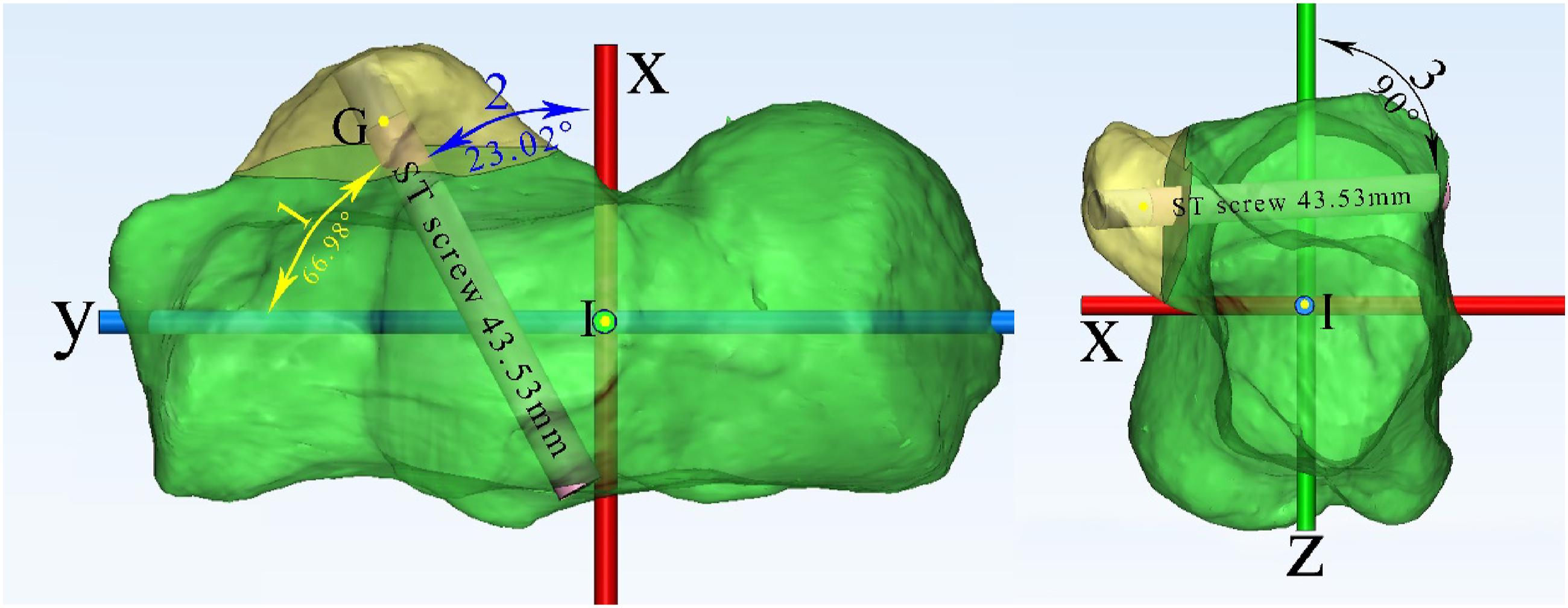
The entry point of ST screw placement
To analyze the optimal location of the entry point, we measured the perpendicular distance from entry points to the lateral edge of PTAS (PDEL). The lateral wall of PTAS was divided into three equal parts. Also, the number of entry points falling on each section was recorded (Figure 5). Lateral view of the left calcaneus. Two blue lines divided the lateral wall of PTAS into three equal parts. A. The anterior one-third part, B. The middle one-third part, C. The posterior one-third part, E. Entry point, G. The ST center, I. The center of calcaneus, L. The lateral edge of PTAS. The yellow line was the PDEL. The optimal PEDL was approximately 10.78 mm.
The accuracy of new screw positioning method
We used six cadaveric feet to verify the accuracy of new screw positioning method (Figure 6). The Department of Anatomy, Southern Medical University, provided these specimens for this study. At the beginning of the surgical procedure, these specimens were positioned to be equivalent to the intra-operative lateral decubitus position on the operating room tables. Single surgeon simulated clinical operation in the laboratory: the lateral wall of PTAs was shown through the extended lateral approach. The new method was used to assist with ST screw placement. This is an example of ST screw successfully placed in a cadaveric right foot. The screw was intentionally kept to be long enough for observation of the angles. a: Calcaneus’s lateral view showed an entry point fell on the middle one-third part, b: ST’s middle view, c: superior view of the foot showed the X angle and Y angle. 1. The lateral edge of PTAS, 2. Lateral malleolus, 3. Fibularis brevis and longus tendon, 4. Entry point, 5. Screw passed the middle of ST. 6. Tibialis posterior tendon, 7. Middle talar articular surface, 8. Flexor digitorum longus tendon, 9. Flexor hallucis longus tendon, 10. Tibial nerve, 11. Posterior tibial artery, 12. Medial malleolus.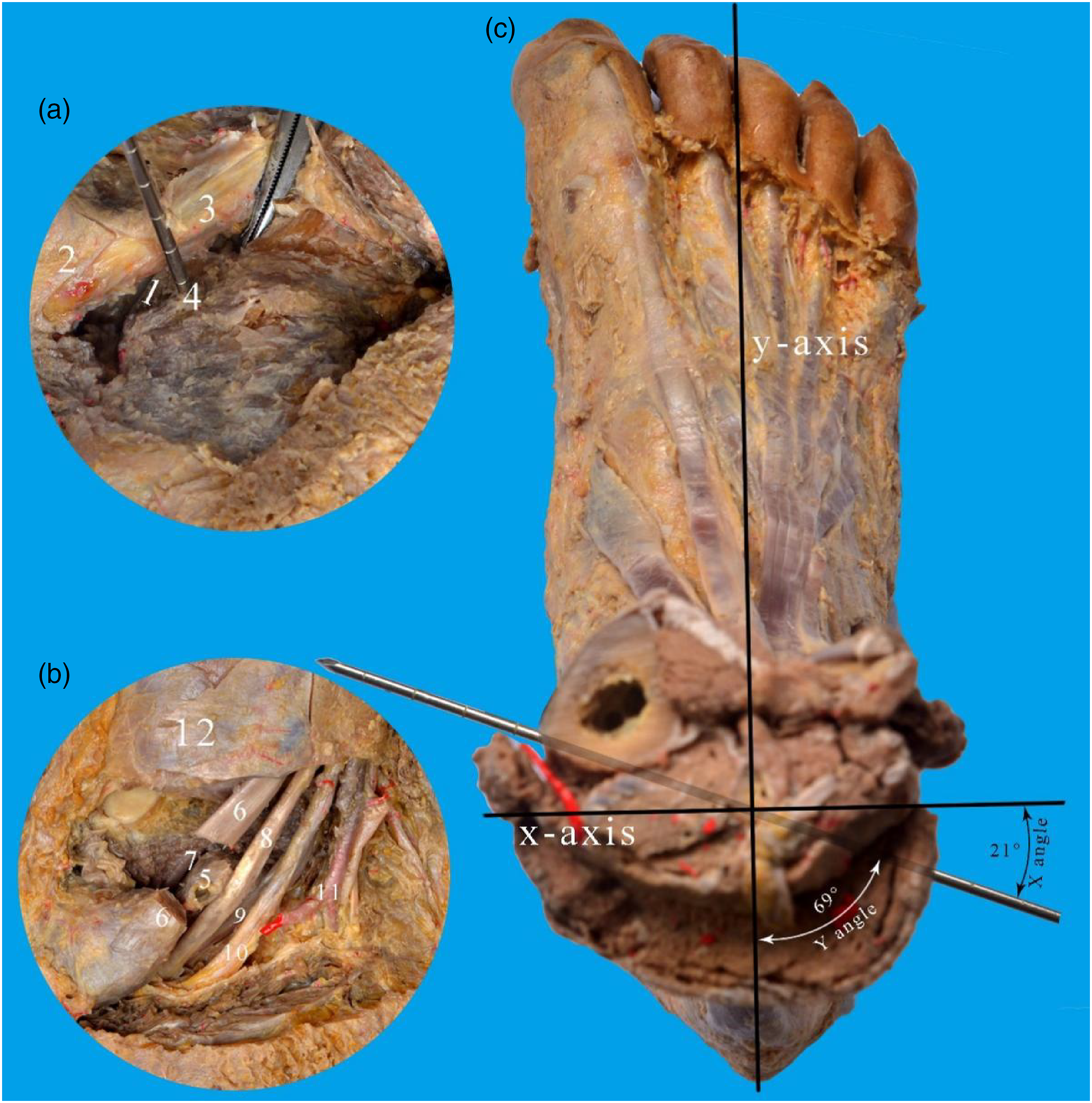
Statistical analysis
Measurements were performed by three independent observers. Statistical analysis was conducted using the SPSS 20.0 software (IBM, USA). To determine the difference of ST heights among the anterior, middle, and posterior sections, one-way ANOVA was performed. Probability values less than 0.05 (p < .05) were considered statistically significant. When differences among ST heights showed significance, a Bonferroni post hoc-test would be conducted following one-way ANOVA. Also, we used a one-sample t-test to see whether the three ST heights differed from the ST screw diameter (4 mm). Parameters before and after applying the new method were compared using paired-sample t-test and one-sample t-test, according to varied data requirements. The sex and left-right difference were analyzed using independent-sample t-tests.
Results
Anatomical measurements of ST
Descriptions and measurements of ST
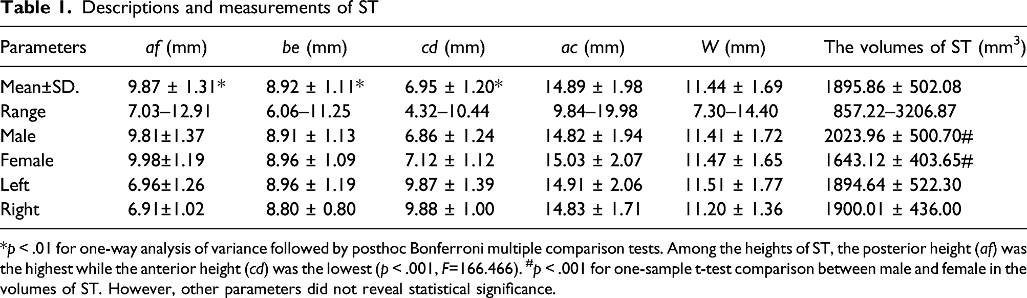
*p < .01 for one-way analysis of variance followed by posthoc Bonferroni multiple comparison tests. Among the heights of ST, the posterior height (af) was the highest while the anterior height (cd) was the lowest (p < .001, F=166.466). #p < .001 for one-sample t-test comparison between male and female in the volumes of ST. However, other parameters did not reveal statistical significance.
The diameter of ST screw was usually 4 or 3.5 mm. Although the heights in three sections all exceeded 4 mm (t = 39.560, p < .001), the volume of ST in male was greater than in female (t = 4.010, p < .001). Therefore, the diameter of the ST screw should be approximately 4.0 mm in male and 3.5 mm in female. The ratio of the average ST volume to the average calcaneus volume (ST excluded) was 0.05 (1:20). All anatomical measurements of ST were shown in Table 1.
The angles and lengths of ST screw trajectory
Measurements of ST screw placement
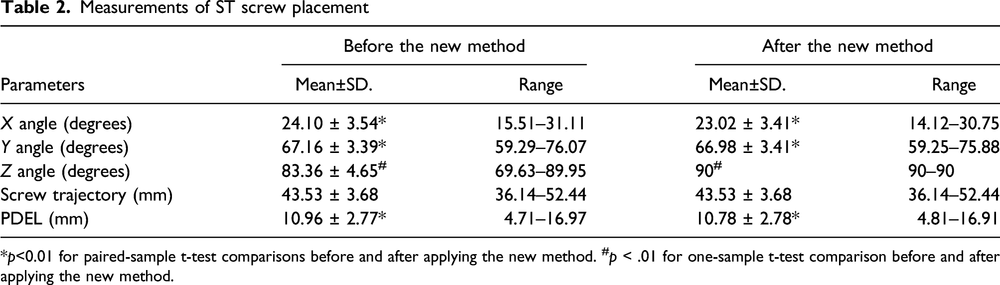
*p<0.01 for paired-sample t-test comparisons before and after applying the new method. #p < .01 for one-sample t-test comparison before and after applying the new method.
Sex and left-right differences in parameters after the new method.

Independent-sample t-tests were used to test sex differences and left-right differences in comparing these parameters. *p < .01 for independent sample t-tests comparisons between male and female.
Observation and measurement of the entry point
After the new method was applied and screw placement was considered successful, the lateral wall of PTAS was divided into three equal parts, then the number of 110 entry points that fell on each part were counted separately. Locations of entry points were as follows: Nine cases (8.1%) fell on the anterior one-third part, 95 cases (86.4%) fell on the middle one-third part, and six cases (5.5%) fell on the posterior one-third part. The PDEL was 10.78 mm (Table 3). No significance was found in PDEL among sex differences (p = .449, t = 0.760) and left-right differences (p = .161, t = 1.410).
Finally, we used six cadaveric feet to verify the validity of the new positioning method. Results showed that ST in all six cadavers were successfully placed with the screw in the medial part. In cadaveric study, the PDEL was 10.80 ± 0.91 mm, the Y angle was 67.79 ± 2.17° and the length of ST was 42.97 ± 2.45 mm.
Discussion
ST has the strongest bone in the calcaneus. Therefore, it is an optimal landing place for screw placement. Surgeons often insist on placing screw fixation on ST, even after reduction of displaced ST fragments.6,7,10,12–14 ST is small in size and irregular in shape, so the risk of screw misplacement was relatively higher. And that may cause injuries to adjacent tendons or neurovascular structures. 6 Though the risk often exists, former researchers did not cover the exact size of ST. Thus, this study measured the size and volume of ST. As a result, ST was 20 times smaller than calcaneus (ST excluded), and the anterior part of ST was the lowest in height, according to mean values. The posterior part of ST was the highest among the three, while the all parts exceeded 4 mm (the diameter of ST screw was usually 4 or 3.5 mm).15,16 Although a 4-mm-diameter screw would be safe and suitable for ST fixation in most cases if under proper usage, the volume of ST in male was greater than in female. Therefore, the diameter of the ST screw should be 4.0 mm in male and 3.5 mm in female. Besides, we measured the average width and length of ST which were 11.44 mm and 14.89 mm, respectively. The average width of ST is similar to that in other studies.17,18 And the average length of ST is close to the results of Sarafian’s (13 mm) but smaller than that of Niladri’s (25.53 mm).18–20 The length was different from that in other studies, because some studies tended to define the fusion of anterior and middle facets as a long sustentaculum, which added to the length of ST.18,19
As mentioned previously, there are three main reasons for the difficulties in ST screw placements. To solve these problems, we should identify the entry points, the length of screw trajectories, and the angles of ST screw placement. Hence, we established a 3 D coordinate system based on the reference lines. At present, no consensus on the definition of optimal reference lines has been reached. Here are some reference markers that were commonly used in former studies: the longitudinal axis of the calcaneus, 6 the floor, 6 PTAS, 16 the highest point of calcaneal tuberosity, 21 etc. In fact, the axis of the whole foot is more important to surgeons than the calcaneal axis because the axis of the entire foot is more practical in surgical positions. Thus, we choose the following markers to establish the 3 D coordinate system: the longitudinal axis of the whole foot, I point, and H point.
In this study, a new ST screw placing method was created and considered successful based on the criteria mentioned above. By this new method, the ST screw would be perpendicular to the z-axis in the calcaneus and then 66.98° to the y-axis. This new method has practical applications as it references the axis of the entire foot. Using this new method, only two angles (Z angle and Y angle) need to be adjusted during ST screw placement, because X angle and Y angle always add up to 90°. Therefore, it would be easy for surgeons to remember and identify the starting angles when positioning an ST screw.
At present, few studies reported the length of ST screw trajectory. As we all know, a too-long screw has a potential clinical impact on soft tissues. Choosing an ST screw with appropriate length is necessary for avoiding damage to the soft tissues. In this study, the mean value of the ST screw trajectory length was 43.53 mm. This is close to the results of some other studies (approximately 40 mm).10,16 Besides, according to our results, females (44.14 mm) tend to have a shorter screw trajectory than males (41.74 mm), and it should be noticed when placing a screw.
The optimal entry point has been looked at by multiple other studies with no real consensus. For example, some researchers proposed that the entry point should locate below the middle part of the lateral edge of PTAS, and too anterior or too posterior were not appropriate21,22 while other researchers believed the optimal entry point should have a PEDL of 15 mm and the anterior, middle and posterior parts of the lateral wall of PTAS were all suitable for screw placement. 16 Although the definition of entry point varies, there are always two essential parameters: the PDEL and the part of the entry point that locates at the lateral wall of PTAS (anterior, middle, or posterior one-third section). In this study, we adopted a new ST screw placing method, then measured the PDEL. 85% of entry points were on the middle one-third part of the lateral wall of PTAS. The PDEL was 10.78 mm. In summary, the optimal entry point should locate at the middle part of the lateral wall of PTAS, and 10.78 mm below the lateral edge of PTAS.
The main goal of the current study was to provide reliable references for clinicians to perform ST screw fixations safely. This paper investigates the parameters of a successfully placed ST screw, and describes a new method to help place ST screw successfully. We verified this new method in cadavers and achieved a full success rate. Therefore, we believe our study could, to some extent, help surgeons place ST screws accurately.
There were several limitations in this study. First, our study sample size was 110 participants which was not large enough to represent the whole population. Also, the results may only apply to the Asian population. In the future, we will increase the sample size to reach more solid conclusions. Second, we collected data from only one institution. Thus, we will consider performing multi-center research further. Third, the materials we measured were normal calcaneus with intact ST. However, when ST was fractured, an open reduction of the calcaneus may not have the perfect anatomy as a normal one. At last, we did not analyze the age differences because calcaneus was fully grown after 16. We verified this new method in cadavers, but we only have six specimen which lack representativeness.
Conclusions
To help achieve successful ST screw placement in the Asian population, we have the following suggestions. First, the entry point should have a PEDL of 10.78 mm and locate at the middle section of the lateral wall of PTAS. Second, the ST screw should be perpendicular to the z-axis and the screw should position at 66.98° to the longitudinal axis of the whole foot. Third, the length of the ST screw should be approximately 44.74 mm in male and 41.14 mm in female. Fourth, the diameter of the ST screw should be approximately 4.0 mm in male and 3.5 mm in female.
Footnotes
Acknowledgments
We greatly appreciate the effort of every person that is associated with this project.
Authors’ contributions
Each Authors contributed substantially to this study including study design, literature research, data acquisition, data analysis, and manuscript drafting.
Declaration of conflicting interests
The author(s) declared no potential conflicts of interest with respect to the research, authorship, and/or publication of this article.
Funding
The author(s) received no financial support for the research, authorship, and/or publication of this article.
Author’s note
These authors contributed equally to the work and should be regarded as co-first authors: Li-qing Liao and Zi-yu Feng
Ethical approval
This study had approvals from the institutional review board.
Informed consent
The requirement for informed patient consent was waived. This study was also compliant with the current regulations of our country.
Consent for publication
All authors have read and approved the final manuscript.
Data availability
All data generated or analyzed during this study are included in this published article.
Abbreviations
ST:Sustentaculum Tali; PTAS: Posterior talar articular surface; PDEL: Perpendicular distance from the entry point to the lateral edge of posterior talar articular surface; MTAS: Middle talar articular surface.