
Abstract
In present work, tribology tests were enacted to analyze the wear behavior of composite reinforced with Aloe vera, Corn, Eucalyptus and Soybean Fiber and Epoxy resin. Fatigue and creep tests were accomplished to evaluate the strength of prepared composite specimen under fluctuating and static load conditions. Tribological analysis revealed that hybrid composites achieved higher frictional force as compared to single fiber-based composites. Hybrid ACESE composite exhibits maximum frictional force of 14.01 N, 35.78 N and 37.46 N at 10, 30 and 50 N load for 5 m/s sliding speed as compared to other prepared composite specimens. COF of prepared composite samples were calculated at different sliding speeds (3, 5 and 7 m/s) and applied load of 10, 30 and 50 N load. Hybrid ACESE composite shows maximum value of COF at 10, 30 and 50 N load for 3, 5 and 7 m/s sliding speed. Sliding speed (3, 5 and 7 m/s) with respect to applied load (10, 30 and 50 N) shows the variations in specific wear rate (SWR) for all prepared specimens. During tribological analysis, higher frictional force achieved by hybrid ACESE composite exhibits the highest value of interfacial temperature at 5 m/s sliding speed for 10, 30 and 50 N applied load. While the lower value of frictional force achieved by CE composite displays the lowest value of interfacial temperature at 5 m/s sliding speed for 10, 30 and 50 N applied load. The fatigue test illustrated that hybrid ACESE composite attained the highest fatigue number of cycles at 3822, 3217 and 2218 for 25, 50 and 75% UTS. While CE composites resulted in the lowest fatigue number of cycles at 2234, 1826, and 1219 for 25, 50 and 75% UTS among all prepared specimens.
Introduction
In the field of materials, sustainability of materials is growing due to huge amounts of pollutions forthcoming from fossil fuels and synthetic products which are forming the non-toxic plastics. 1 The toxicity of synthetic plastics harms human beings and animals as well as creating water pollution and damaging sea foods. These synthetic plastics have non decomposing behavior over the thousands of years they continuously create toxic gases which impart the human health and depletes the ozone layer and birth the many deceases in humans and animals.2–4 Governments of many countries are implementing strong laws against the huge consumption of synthetic plastics and promoting the uses of biodegradable resources to manufacture ecofriendly plastics with non-toxic nature. Researchers and scientists are exploring natural resources and extracting their raw materials to utilize them for different ingredients of materials. These raw ingredients are processed by various chemical treatments and then converted into the form of fibers and used as a reinforcement in composite materials. Stems and leaves of plants like jute, hemp, coconut, abaca, sisal etc. provide the natural fibers while skin and hairs of animals like sheep wool, horsehair, chicken feather etc. also serve as reinforced fibers in composite materials. Different minerals like asbestos are also employed as fiber in composite materials. Some natural ingredients like banana sap, coconut water etc. are used as a resin to form the biopolymers. 5
The combination of these natural reinforcements and bio polymer resin builds the bio polymer composite materials which gives competent strength with low weight and virtuous structural stability. 6 These bio composites easily degrade after completing their serviceable life and researchers are trying to replace synthetic plastics with these bio-degradable plastics in diverse structural and non-structural composites. Researchers are focusing on where consumption of synthetic plastics is more with requirement of non-loading applications like packaging applications, storage, household products etc. But this limitation of application does not fulfill the demand of sustainability and so researchers are trying to enhance the structural stability of polymeric materials by reinforcing various natural fillers and fibers and characterize them for mechanical properties, tribological performance, fatigue strength, creep strength etc.7,8 Based on the evaluated tribological, fatigue, and creep performance, the Aloe vera-, Corn-, Eucalyptus-, and Soybean fiber reinforced epoxy composites are primarily envisioned for light-to-medium load structural and semi-structural applications, where sustainability, wear resistance, and long-term mechanical stability. Potential applications include: Automotive interior components (door panels, dashboards, trims, and seat backings), building and construction elements (partition boards, wall panels, false ceilings, and interior cladding), industrial panels and casings (machine covers, housings, and protective enclosures), furniture and consumer products (tabletops, shelves, and modular panels), agricultural and eco-friendly engineering components (lightweight covers, trays, and low-speed sliding parts).9–13
Incorporated natural fibers and fillers provide strength during sliding and various types of forces and withstand these composites in different components of automobiles, aerospace, marine and construction industries. Application of these composite materials requires the prior characterization of composite specimen on characteristics which plays an important role during real essential services. After checking the required characteristics, these composites replaced the synthetic materials and enhanced the sustainability goals managed by the government.13–16
Name of prepared composite specimens.

Methods and materials
The composite samples were constructed using fiber reinforcement of Eucalyptus,,Soybean fiber, Aloe vera and Corn and bidirectional mat. Compact Buying Services, based in Faridabad, India, arranged all these fibers had a thickness of 0.30mm.
While epoxy polymer was employed in the form of hardener (HY 951) and resin. Excellence Resins, Meerut, state of Uttar Pradesh, India arranged epoxy polymer for this study. Selected epoxy resin and hardener has a density ranging from 1.15–1.20 g/cm3 and 10–20 mPa×s.
Representations of weight percentage fiber reinforcement and polymer matrix of the prepared samples.


Prepared composite specimen fiber reinforced polymeric composites.
Experimental investigations
All experiments in this study were conducted in triplicate (n = 3) to make sure repeatability. The reported average values provide a measure of variability and data reliability and confirms that the observed trends in mechanical, creep, fatigue, and tribological performance are dependable and reproducible.
Fatigue test
Fatigue number of cycles were calculated using fatigue test to evaluate the fatigue life of composite samples. Fatigue testing machines (5900 Horizontal fatigue set-up) of PSI Sales Noida were used to calculate fatigue number of cycles until failure for developed samples.
Creep test
Creep testing was staged to estimate the strength of the composite specimen at continuous loading at elevated temperatures. ASTM D7337 standard was used to prepare the specimens of creep test. The maximum duration of the creep test was 15,000 seconds, with an operating temperature of 45°C.
Tribological testing
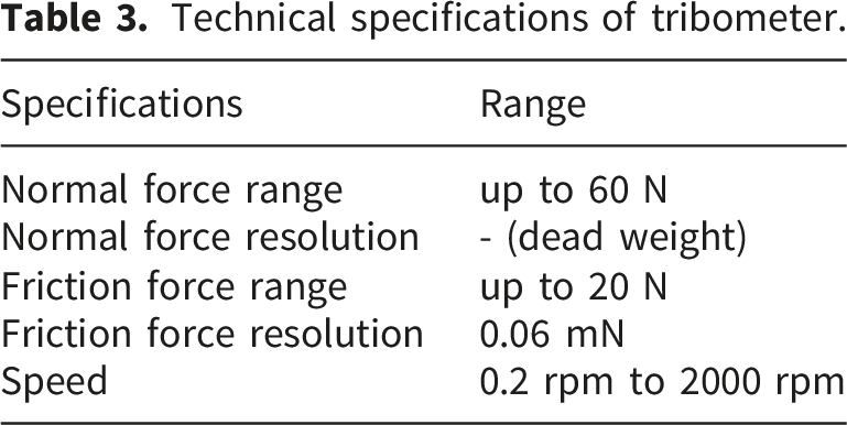
Technical specifications of tribometer.
The coefficient of friction was calculated using friction force and normal load applied by the following equation 1.
The specific wear rate of the test samples was computed using the following equation 2.
Result & discussion
Analysis of fatigue test
Whenever composite specimens encounter fluctuating loads then possibilities of crack initiation produce the plastic deformation of material which fails the material prior to their service life. To overcome this problem, fatigue analysis tests the specimens under fluctuation loads and calculates the fatigue number of cycles at different stress levels of specimen. This testing helps to analyze the specimen life in terms of fatigue cycles sustained during their service life. Figure 2. displayed the fatigue number of cycles with respect to ultimate tensile strength (25, 50 and 75% UTS) of composite samples. Experimental findings of the fatigue test showed that hybrid ACESE composite attained the highest fatigue number of cycles at 3822, 3217 and 2218 for 25, 50 and 75% UTS. While hybrid CSE and AEE composite achieved the second and third highest fatigue number of cycles. Results of fatigue number of cycles with respect to ultimate tensile strength of composite samples.
The superior performance of the hybrid ACESE composite compared to single fiber based reinforced epoxy composites accredited to the strong interrelationship between fatigue resistance due to interfacial integrity and stress transfer efficiency. The hybridization of Aloe vera, Corn, Eucalyptus, and Soybean fibers delivers a collaborative reinforcement effect, helps uniform stress distribution, effective load sharing among fibers with different mechanical characteristics. These mechanisms mutually develop resistance to wear, delay fatigue failure, and reduce creep deformation when compared to single-fiber composites.17,18 Single fiber-reinforced polymer composites exhibit shorter fatigue life compared to hybrid fiber-reinforced composites, primarily due to the varying surface properties of the fibers. Corn fiber reinforced composites got lower fatigue number of cycles at 2234, 1826, and 1219 for 25, 50 and 75% UTS. SE composite represents 3010, 2688 and 1867 fatigue number of cycle and AE composite shows 2905, 2518 and 1777 fatigue number of cycle at 25, 50 and 75% UTS. While EE composite sample exhibits 2815, 2410 and 1667 fatigue number of cycle at 25, 50 and 75% UTS. Zakaria et al. 12 investigates the fatigue behavior of fiber glass reinforced epoxy polymer composites. Authors concluded that fiber orientation affects the fatigue strength to composite specimen. They also concluded that fiber orientation of [0/90°] achieved higher fatigue strength based on unidirectional fiber mat. Silva et al. 13 deliberate the fatigue assessment of sisal fiber-based composites. Authors found that composites below 6 MPa show no crack initiation but plastic deformation occurs above or at 6 MPa up to 106 cycles. Capela et al. 14 conducted the fatigue test for short carbon/epoxy composites. Authors concluded that fatigue life is primarily affected by fiber dispersion and porosity. They also found that lower percentage of fibers within composite lowers the fatigue strength of composite, so a balanced fiber percentage optimized the fatigue number of cycles. Zaghloul et al. 15 examines the fatigue life of fiber-reinforced thermosetting composites inserted with nanoparticles. They select the 2%, 4% and 6% percentages of cellulose nanocrystals for composite fabrication. Authors concluded that incorporation of 4% cellulose nanocrystals to polyester matrix provides the optimized fatigue strength. Seal et al. 4 develops the hybrid composites of sisal, kenaf and pineapple fiber based polymer composites. Similar to the present study, authors found that hybridization of fibers helps to enhance the stress distributions and structural stability of developed composites which shows the maximum fatigue cycles at different ranges of ultimate tensile strengths.
Analysis of creep test
Whenever composite specimens encounter static loads then possibilities of molecular change construct the plastic deformation of material which fails the material prior to their service life. To overcome this problem, creep test performs under static loads and calculates the creep strain with respect to time of specimen. This testing helps to analyze the specimen life in terms of creep strain incurred throughout their service life. Figure 3 illustrates the creep strain over time, ranging from 2000 to 15,000 seconds. A lower creep strain over this period indicates good structural stability of the prepared specimen, suggesting strong interfacial adhesion between the reinforcing fiber phase and the polymer matrix. Experimental results exhibit that developed hybrid composite shows less creep strain compared to only one type of fiber based composite sample. These findings indicate the advantages of different surface characteristics of different fibers combined which enhanced the wettability of fibers with polymer resin and improve the interfacial interaction of developed composites which lowers the creep strain. Minimum and maximum creep strain was exhibited by ACSE and CE composite was 0.004 and 0.032 for 15000 sec. While other hybrid composites like CSE and AEE show 0.008 and 0.012 creep strain for 15000 sec. SE, EE and AE composite depicted the creep strain of 0.019, 0.029 and 0.023 for 15000 sec. The superior performance of the hybrid composites occurs from the jointly reinforcing interaction between tribological stability, creep resistance, and fatigue durability. Qin et al.
16
analyzed the creep examination of fiber reinforced polymer through fiber/matrix interaction. They chose the carbon FRP and glass FRP composite and vital features for fiber/matrix interfacial interactions was the mobility of polymer chains, microstructural evolution at the interface, and the energy changes during the creep process. Authors found that carbon FRP proves a higher creep strength underneath the same holding load conditions. Du et al.
19
examined the impact of moisture on creep performance of lightweight natural fiber-reinforced polymer composite. Authors concluded that humid environment enhanced the creep strain by from 10% to 30%. Li et al.
20
investigates the creep study of carbon fiber-based nanocomposites. Authors found that temperature influences the creep strain and creep strain intensified due to various factors such as directed stress, time of creep, humidity, and operating temperature. Goertzen et al.
21
performed the creep test on carbon fiber-based epoxy composites. Authors found creep strain generated above 65% ultimate tensile strength of composite specimen for reasonable time. Results of creep strain with respect to time of composite samples.
Analysis of tribology
Frictional force analysis
Frictional force arises due to sliding forces between specimen and rotating steel counterface during tribology test. The value of friction force decides the response of wear behavior and coefficient of friction. Figures 4–6 represents the value of frictional force at 10, 30 and 50 N applied load and 5 m/s sliding speed. All developed composites show the growth in the rate of frictional force whenever it comes in the contact of sliding with respect to applied load. As the sliding time increases, frictional force increased from 0 to 1000 sec and between 1000 to 1500 sec, it becomes constant for each test specimen. But after 1500 sec, frictional force decreases for all test specimens. After 1800 sec, frictional force becomes constant for all test specimens. Among all test specimens, hybrid ACESE composite achieved maximum value of frictional force. Hybrid ACESE composite exhibits upper limit value of frictional force of 14.01 N, 35.78 N and 37.46 N at 10, 30 and 50 N load for 5 m/s sliding speed related to other prepared composite specimens. Hybridization of all selected three fibers with epoxy polymer matrix impacts the surface characteristics of prepared specimen due to different surface properties of each fiber as soyabean and Eucalyptus is rough fiber but aloe vera and corn fiber is smooth fibers. These distinct surface properties enhance the wettability of various fiber mats with epoxy resin, which in turn enhances the interfacial bond by reducing cavities between the fiber and matrix phase. A higher value of frictional force is the consequence of improved interfacial adhesion, which provides structural stability to the specimen during tribology tests.17,22,23 Similar results were found by Seal et al.
4
for hybrid composites developed using pineapple, kenaf and sisal fiber based polymers. Authors found that hybridization of fibers provides the optimized surface characteristics and heightens the fiber/matrix interfacial adhesion. And strong interfacial adhesion optimized the tribological performance of developed composites. In comparison to single fiber-based composites such as AE, CE, EE, and SE composite samples, the frictional force is higher due to the hybridization of fibers in CSE and AEE composites. In contrast to other prepared specimens, CE composites demonstrate the lowest frictional force throughout the duration of the test. The frictional force of plant-based epoxy composites that were created using Liquid Composite Molding was examined by Barari et al.
18
They examined how the tribological performance of the composites they developed was influenced by their volume fraction. The authors determined that the coefficient of friction (COF) decreases as the volume fraction of bio-epoxy increases for all normal loads of 4 N, 7 N, and 10 N at a modest sliding speed of 0.15 m/s. The tribological efficacy of a bio-waste natural fiber–reinforced polymer hybrid composite was evaluated by Suresh et al.
24
The authors concluded that the 20% bio-hybrid composite exhibited a higher frictional force, low attrition loss, and a low coefficient of friction in all sliding conditions. Results of frictional force at 10 N applied load and 5 m/s sliding speed. Results of frictional force at 30 N applied load and 5 m/s sliding speed. Results of frictional force at 50 N applied load and 5 m/s sliding speed.


Coefficient of friction
Coefficient of friction of composite specimens calculates by the values of frictional force and applied normal load as shown in Figure 7. COF of prepared composite samples were calculated at different sliding speeds (3, 5 and 7 m/s) and applied load of 10, 30 and 50 N load. At 3, 5, and 7 m/s, all composites that have been developed exhibit a marginal decrease in COF when subjected to a 10 to 30 N load. However, the coefficient of friction (COF) exhibits a significant decrease from 30 to 50 N burden at 3, 5, and 7 m/s. In comparison to other test specimens, the Hybrid ACESE composite exhibits the highest COF value at 10, 30, and 50 N load at 3, 5, and 7 m/s sliding speed. The ACSE composite achieves the highest frictional force, as illustrated in Figures 4–6, resulting in the maximum coefficient of friction. The hybrid composites exhibit a higher value of COF due to the highest frictional force of hybrid AEE and CSE composites in comparison to single fiber AE, CE, EE, and SE composites. The surface characteristics of the prepared specimen are influenced by the hybridization of Aloe vera, maize, eucalyptus, and soybean fibers with an epoxy polymer matrix, as a result of the varying surface properties of each fiber. Aloe vera and corn fibers are silky, while soybean and eucalyptus fibers are scratchy. The wettability between the epoxy resin and fiber mats is improved, and the interfacial adhesion and cavities between the fiber and matrix phases are reduced as a result of these differences in surface properties. The specimen’s structural integrity is enhanced during tribological testing, which leads to an increased frictional force, as a result of the enhanced interfacial adhesion.25–27 Results of coefficient of friction at 3, 5 and 7 m/s sliding speed.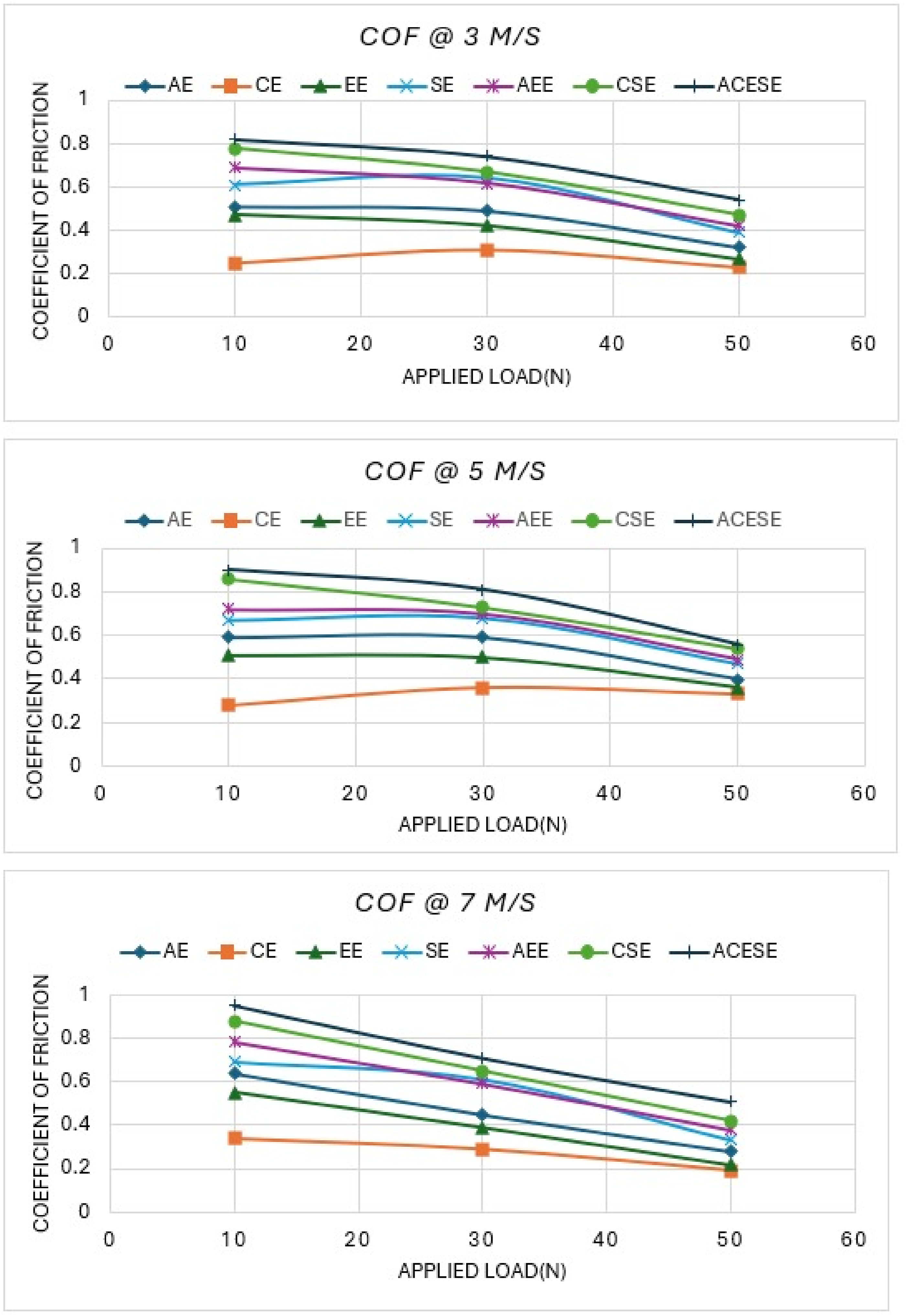
COF at 3 m/s sliding speed
For 10 N applied load, ACESE, CSE, and AEE hybrid composite achieved COF of 0.82, 0.78 and 0.69, while SE, EE, CE and AE composites exhibit COF of 0.61, 0.47, 0.25 and 0.51. For 30 N applied load, ACESE, CSE, and AEE hybrid composite achieved COF of 0.74, 0.67 and 0.62, while SE, EE, CE and AE composites exhibit COF of 0.39, 0.27, 0.23 and 0.32. For 50 N applied load, ACESE, CSE, and AEE hybrid composite achieved COF of 0.54, 0.47 and 0.42, while SE, EE, CE and AE composites exhibit COF of 0.39, 0.27, 0.23 and 0.32.
COF at 5 m/s sliding speed
For 10 N applied load, ACESE, CSE, and AEE hybrid composite achieved COF of 0.9, 0.86 and 0.72, while SE, EE, CE, and AE composites exhibit COF of 0.67, 0.51, 0.28 and 0.59. For 30 N applied load, ACESE, CSE, and AEE hybrid composite achieved COF of 0.81, 0.73 and 0.7, while SE, EE, CE and AE composites exhibit COF of 0.68, 0.5, 0.36 and 0.59. For 50 N applied load, ACESE, CSE, and AEE hybrid composite achieved COF of 0.56, 0.54 and 0.49, while SE, EE, CE and AE composites exhibit COF of 0.47, 0.36, 0.33 and 0.4.
COF at 7 m/s sliding speed
For 10 N applied load, ACESE, CSE, and AEE hybrid composite achieved COF at 0.95, 0.88 and 0.78, while SE, EE, CE and AE composites exhibit COF of 0.69, 0.55, 0.34 and 0.64. For 30 N applied load, ACESE, CSE, and AEE hybrid composite achieved COF of 0.71, 0.65 and 0.59, while SE, EE, CE and AE composites exhibit COF of 0.61, 0.39, 0.29 and 0.45. For 50 N applied load, ACESE, CSE, and AEE hybrid composite achieved COF of 0.51, 0.42 and 0.38, while SE, EE, CE and AE composites exhibit COF at 0.33, 0.22, 0.19 and 0.28.
Egala et al. 22 investigated the COF of castor oil fiber-based composites that were produced using the manual lay-up method. The tribological properties of the composites that were developed were examined in relation to the length of the fibers. In order to determine the coefficient of friction (COF) of composite specimens that have been prepared, they have chosen four fiber lengths (5, 10, 15, and 20 mm), three normal pressures (15, 30, and 45 N), and three sliding distances (1,000, 2,000, and 3,000 m). The authors concluded that the optimum value of COF of the prepared composite specimen was obtained by 40 vol% unidirectional short 5 mm-fiber length castor oil fibers-based epoxy composites. The tribological efficacy of the bamboo/epoxy composite was examined by Alajmi et al. 28 The authors determined that COF decreases as the applied burden increases in relation to various sliding velocities. The friction coefficient of polypropylene composites reinforced with flax and glass fiber was investigated by Chegdani et al. 29 They determined that flax fibers produce more friction than glass fibers in polypropylene composites.
Specific wear rate analysis
The most critical parameter in tribological tests is the specific wear rate analysis, which is used to estimate the material elimination during sliding at varying velocities in relation to the applied load, as illustrated in Figure 8. The variations in specific wear rate (SWR) for all prepared specimens are demonstrated by the ratio of sliding speed (3, 5 and 7 m/s) to applied load (10, 30 and 50 N). The specific wear rate (SWR) of hybrid composites (ACESE, CSE, and AEE) is lower than that of single fiber-reinforced composites (SE, EE, CE, and AE) due to the increased frictional force. SWR increases as the applied load increases from 10 to 30 and 50 N. A similar increase in SWR is observed when the sliding speed is increased from 3 to 5 and 7 m/s in relation to the applied load. The Hybrid ACESE composite obtained a minimum SWR of 4.1, 30.1, and 42.1 mm3/N-mm at a sliding speed of 3 to 5 and 7 m/s under a 10 N applied stress. CE composite obtained a maximum SWR of 16.4, 98.4, and 99.8 mm3/N-mm at a 50 N load and a sliding motion of 3 to 5 and 7 m/s. Results of specific wear rate at 3 m/s sliding speed.
SWR at 3 m/s sliding speed
For 10 N applied load, ACESE, CSE, and AEE hybrid composite achieved SWR of 4.1, 5.8 and 5.9 mm3/N-mm, while SE, EE, CE and AE composites exhibit SWR of 6.7, 8.9, 11.4 and 8.8 mm3/N-mm. For 30 N applied load, ACESE, CSE, and AEE hybrid composite achieved SWR of 4.3, 6.1 and 6.4 mm3/N-mm, while SE, EE, CE and AE composites exhibit SWR of 7.2, 9.3, 11.9 and 9.1 mm3/N-mm. For 50 N applied load, ACESE, CSE, and AEE hybrid composite achieved SWR of 9.3, 11.2 and 11.9 mm3/N-mm, while SE, EE, CE and AE composites exhibit SWR of 12.5, 13.6, 16.4 and 13.4 mm3/N-mm.
SWR at 5 m/s sliding speed
For 10 N applied load, ACESE, CSE, and AEE hybrid composite achieved SWR of 30.1, 37.4 and 38.1 mm3/N-mm, while SE, EE, CE and AE composites exhibit SWR of 42.6, 47.1, 67.2 and 46.4 mm3/N-mm. For 30 N applied load, ACESE, CSE, and AEE hybrid composite achieved SWR of 31.2, 42.7 and 44.9 mm3/N-mm, while SE, EE, CE and AE composites exhibit SWR of 49.6, 53.8, 59.9 and 54.1 mm3/N-mm. For 50 N applied load, ACESE, CSE, and AEE hybrid composite achieved SWR of 55.1, 67.5 and 68.4 mm3/N-mm, while SE, EE, CE and AE composites exhibit SWR of 74.2, 81.4, 98.4 and 82.7 mm3/N-mm.
SWR at 7 m/s sliding speed
For 10 N applied load, ACESE, CSE, and AEE hybrid composite achieved SWR of 42.1, 45.8 and 49.2 mm3/N-mm, while SE, EE, CE and AE composites exhibit SWR of 52.2, 56.7, 74.8 and 57.2 mm3/N-mm. For 30 N applied load, ACESE, CSE, and AEE hybrid composite achieved SWR of 37.9, 45.3 and 47.5 mm3/N-mm, while SE, EE, CE and AE composites exhibit SWR of 42.2, 56.3, 72.8 and 56.7 mm3/N-mm. For 50 N applied load, ACESE, CSE, and AEE hybrid composite achieved SWR of 58.3, 70.8 and 71.7 mm3/N-mm, while SE, EE, CE and AE composites exhibit SWR of 77.5, 84.6, 99.8 and 85.1 mm3/N-mm.
High friction and low specific wear rate in the ACESE hybrid composite occurred in tribological analysis due to transfer layer formation and interfacial stability. The high friction develops from strong fiber/matrix interactions and surface sharpness meeting, which increases interfacial resistance. Concurrently, the hybrid fibers progress the development of a compact, protective transfer layer composed of wear debris and partially exposed fibers. This layer cut down direct contact between the sliding surfaces which limiting material removal and resulting in a low specific wear rate.17,18,24 Bajpai et al. 30 investigated the PLA composites based on Grewia optiva fibers (GOF) and nettle fibers (NF). The authors determined that the weight loss in the clean PLA specimen is significantly elevated during the wear test. However, composites that have been constructed with the reinforcement of natural fibers exhibit structural stability during sliding in tribology testing. This demonstrates that the wear performance of clean PLA has been improved by the addition of natural fiber reinforcement. The wear test for Eulaliopsis binata fiber epoxy composites was conducted by Pradhan et al. 31 They investigated the impact of varying weight percentages of Eulaliopsis binata fiber on the wear behavior of the composites that were developed. The authors determined that the minimal wear rate is achieved by selecting the applied loads and sliding speed during tribology experiments, which includes 30 wt.% of fiber and 70 wt.% of polymers.
Interfacial temperature
When composite specimen slides over the steel counterface then friction generates the temperature between the sliding surfaces. That temperature increases the thermal degradation at the sliding surface of the specimen. Higher temperature transfers the rigid state of composite specimen to the rubbery state. At rubbery state, composite specimens stick to the steel counterface, and large amount of wear starts due to sticking of the specimens and specimens start the breaking into the patches. Figure 9 illustrates the interfacial temperature of the composite specimen that was prepared during the tribology test. At a sliding speed of 5 m/s, the interfacial temperature reaches its highest value when the hybrid ACESE composite achieves a higher frictional force while applying a load of 10, 30, or 50 N. While the CE composite achieves the lowest value of frictional force, the interfacial temperature is at its lowest at a sliding speed of 5 m/s for applied loads of 10, 30, and 50 N. Hybrid composites represent higher frictional force as compared to single fiber-based composites. Results of interfacial temperature during tribological analysis.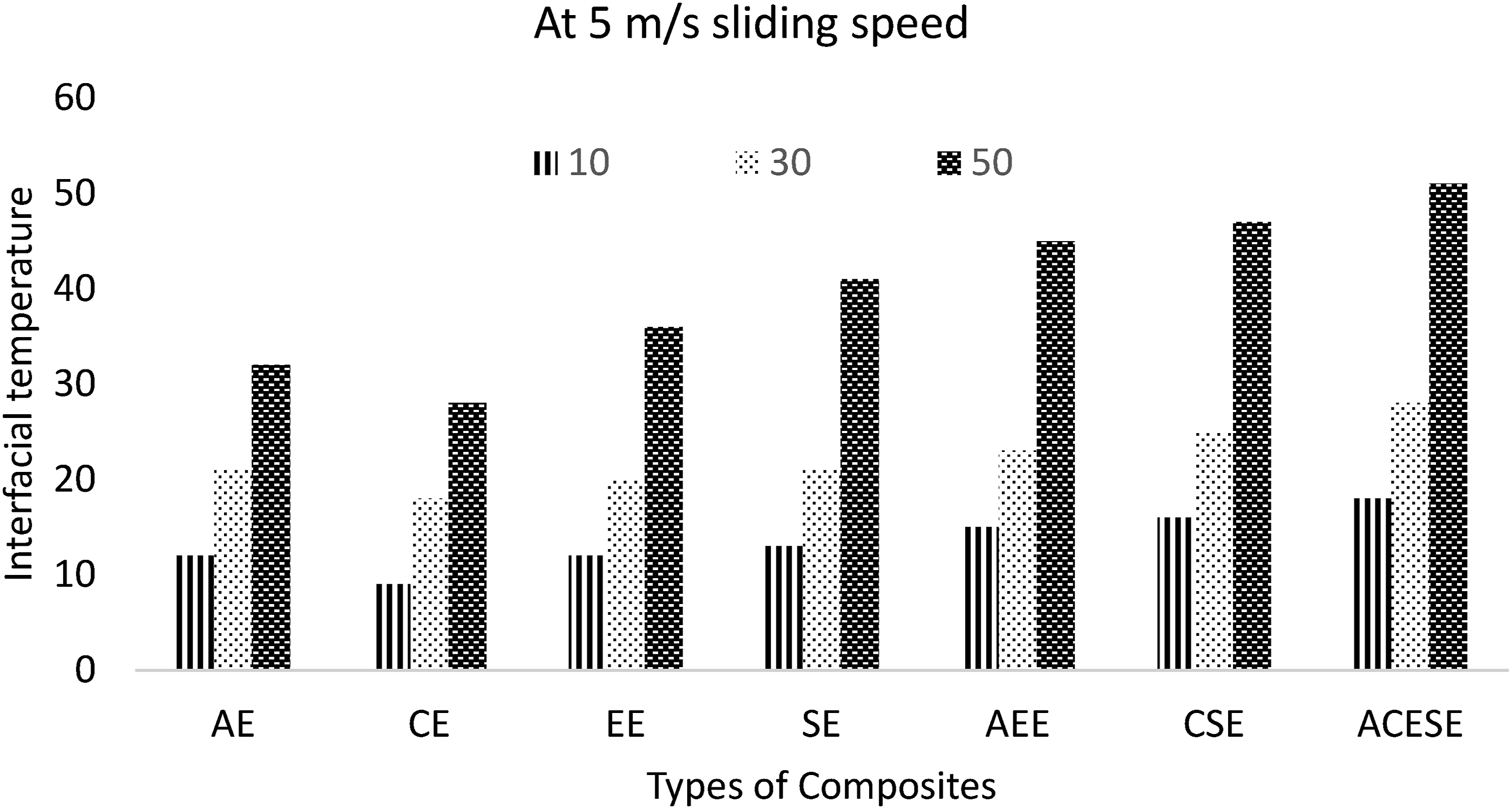
Interfacial temperature at 5 m/s sliding speed
For 10 N applied load, ACESE, CSE, and AEE hybrid composites establish interfacial temperatures of 18, 16 and 150C, while SE, EE, CE and AE composites exhibit interfacial temperatures 13, 12, 9 and 12 0C. For 30 N applied load, ACESE, CSE, and AEE hybrid composite indicate interfacial temperatures of 28, 25 and 230C, while SE, EE, CE and AE composites exhibit interfacial temperatures of 21, 20, 18 and 210C. For 50 N applied load, ACESE, CSE, and AEE hybrid composite indicates interfacial temperatures of 51, 47 and 450C, while SE, EE, CE and AE composites exhibit interfacial temperature 41, 36, 28 and 320C. Seal et al. 4 also conducted a comparable investigation on epoxy hybrid composites that were filled with coconut shell, seashell, and eggshell, as well as pineapple, sisal, and kenaf fiber. They determined that the interfacial temperature between the specimen and steel counterface is enhanced by increasing the applied load and sliding speed for the composites that have been developed. Also, the specimen undergoes a transition from a vitreous to a rubbery state as the interfacial temperature rises, resulting in increased attrition as a result of its adhesion to the steel counterface.
Wear mechanism
The wear mechanism demonstrates the process of deformation of specimen during tribology tests. The degradation of material is contingent upon the sliding speed and applied load in relation to the sliding distance in composite specimens that have been developed, where both the matrix and reinforcement are involved in the sliding process. The reinforcement phase in prepared composites was arranged in bi-directional mat, in which fiber threads are arranged in longitudinal and transverse direction. While composite specimen slides against the steel counterface, then a large volume of epoxy surface comes in the contact of steel counterface and due to the brittle nature of the epoxy, large amount friction generates. After that, reinforced fiber will take part and enhance the frictional force value. In bidirectional mat, the first longitudinal fiber will come in contact to the sliding surface and wear out easily but when transverses fiber come then their large surface area enhances the frictional force value and tries to hold the stability of specimen with slow deformation. Combination of longitudinal and transverse direction of reinforced fiber confirms the better stability to the composite specimen during tribology test.
Conclusion
The tribological performance of composite samples that were developed in this study was assessed using epoxy polymer resin as a matrix and reinforced with Aloe Vera, Corn, Eucalyptus, and Soybean fibers. In order to evaluate the composite specimens’ efficacy under static and cyclic loading conditions, fatigue and creep experiments were implemented.
The resulting points can be concluded from the existing results: 1. The structural stability of the prepared specimens is demonstrated by tribological experiments, which demonstrate that the merging of various reinforced fibers with the epoxy matrix is effective in sliding conditions. The interfacial linkage between fiber and matrix was enhanced by the hybridization of all three selected fiber mats with epoxy matrix, resulting in a reduction of cavities. The frictional force performance is enhanced as a result of the hybridization of various fibers. In comparison to single fiber-based composites such as AE, CE, EE, and SE composite samples, the frictional force is higher due to the hybridization of fibers in CSE and AEE composites. In contrast to other prepared specimens, CE composites demonstrate the lowest frictional force throughout the duration of the test. 2. The composite specimens that have been prepared demonstrate a marginal decrease in COF from a 10 to 30 N burden at 3, 5, and 7 m/s. However, the coefficient of friction (COF) exhibits a substantial decrease from 30 to 50 N when the burden is applied at 3, 5, and 7 m/s. In comparison to other test specimens, the Hybrid ACESE composite exhibits the highest COF value at 10, 30, and 50 N load at 3, 5, and 7 m/s sliding speed. The hybrid composites exhibit a higher value of COF due to the highest frictional force of hybrid AEE and CSE composites in comparison to single fiber AE, CE, EE, and SE composites. 3. Specific wear rate depends on the performed frictional force of composite specimens during sliding. The higher value of frictional force of hybrid composites (ACESE, CSE, and AEE) shows lower value of SWR in hybrid composites as compared to single fiber-based composites (SE, EE, CE and AE). As the applied load increases from 10 to 30 and 50 N, SWR increases and similar increment in SWR shows when sliding speed increased from 3 to 5 and 7 m/s with respect to applied load. The Hybrid ACESE composite achieved minimum SWR. While Maximum SWR was achieved by CE composite at 50 N load for 3 to 5 and 7 m/s sliding speed. 4. The interfacial temperature during sliding in tribology test between specimen and steel counterface stick the specimen to the steel counterface, and large amount of wear starts due to sticking of the specimens and specimens starts the breaking into the patches. Higher frictional force attained by hybrid ACESE composite exhibits the highest value of interfacial temperature at 5 m/s sliding speed for 10, 30 and 50 N applied load.
Footnotes
ORCID iDs
Author contributions
All authors are equally contributed to Conceptualization, Methodology, Writing - original draft, Writing - review & editing.
Funding
The authors received no financial support for the research, authorship, and/or publication of this article.
Declaration of conflicting interests
The authors declared no potential conflicts of interest with respect to the research, authorship, and/or publication of this article.
Data Availability Statement
The data that support the findings of this study are available on request from the corresponding author.
AI declaration
The authors acknowledge the use of Grammarly, an AI-based language assistance tool, to support grammar, spelling, and language clarity improvements during the manuscript preparation.