
Abstract
Advanced composites have been widely adopted as a material of choice within the aerospace industry for more than 40 years, owing to their exceptional quality, low density, and high stiffness and strength. However, their complex nature of damage continues to pose challenges for structural repairs. Since damage is inevitable in any structure, a reliable and efficient repair technique is essential to support the ongoing use of composites across various industries and applications. A viable repair method should account for the limitations of available equipment and resources, as well as the preservation of repair materials, particularly for rapid repairs with minimal aircraft downtime. This paper reviews the application of resin injection for repairing aircraft composite structures as a non-invasive and cost-effective alternative to existing repair methods. The primary focus of this review is on the resin’s ability to infiltrate the damaged area, as this directly influences the rate of strength recovery. Many researchers have assessed the injection method’s tolerance and strength restoration capacity while suggesting or recommending certain processes. However, achieving complete penetration remains challenging, especially for more complex damage caused by impact.
Introduction
Due to their superior quality, weight savings, good damping properties, corrosion resistance, and the ability to be engineered into any desired shape, composite materials have been increasingly used in airframe structures.1,2 The percentage increase in the use of composites in the structural weight of fixed and rotary-wing aircraft (52% in the A350XWB and 90% in the NH90) is driven by the continuous development of advanced manufacturing systems and non-destructive inspection techniques.3,4 Reducing aircraft weight to address fuel consumption and CO2 emissions, along with increasing service life to mitigate aircraft aging, are key drivers for advanced material technologies in the aerospace industry. This has led to the development of several concepts, including the use of composites to replace aging aircraft components that are no longer available. 5
Unlike damages associated with metals (such as fatigue cracks and corrosion), composite structures are more vulnerable to in-service damage caused by manufacturing defects, mechanical or foreign object impacts, environmental degradation, overheating, and/or overtightening of fasteners.6–8 To ensure that impact damage does not cause delamination resulting in catastrophic failure, composite structures are often designed with a safety factor of 3 or more. 9 Even with this safety factor, damage to any structure is unavoidable, implying that restoring or improving the qualities of a damaged structure close to the original (intact) condition will, at some point, be required to maintain its structural integrity and functionality. 10 The choice between repair and replacement depends on the level of damage, 11 feasibility and cost-effectiveness of each option,8,12 and other factors. For aircraft maintenance, repair, and overhaul (MRO) centres, repair is usually preferred since replacing damaged parts is costly, 13 especially for complex components that are highly integrated. 14 Repairing composite structures typically involves inspection for damage assessment, removal of the damaged area and treatment of contamination, preparation of the repair material for application to the parent structure, inspection of the repair, and surface finishing. 15 The primary and most widely used damage assessment method is visual inspection, which is routinely employed for pre- and post-flight checks, as well as regular maintenance. However, it is limited to detecting only visible damage.16,17
Due to the continuous stresses and cyclic loads experienced by aircraft during both ground and flight operations, wear and tear typically builds up, resulting in damage over time. Consequently, repairs become unavoidable during the operational phase of an aircraft’s lifecycle; a process aimed at restoring the aircraft to a serviceable condition between its deployment and retirement phases. 18 Initially, with aircraft constructed from metals, the traditional repair method involved applying metal sheets or machined doublers made of aluminium, titanium, or steel to damaged areas, using bolts or rivets. 19 However, this method posed challenges, such as fatigue cracking and aerodynamic inefficiency due to surface disruption caused by protruding fasteners. 12
Advancements in materials science and technology led to the use of composites, specifically fibre-reinforced plastics, for repairing metallic structures, as seen in bonded (boron) patch repairs. 20 This composite repair method saved millions of dollars in maintenance and repair costs while extending the aircraft’s service life, as utilised by the Royal Australian Air Force and subsequently adopted globally. 21 With the increased use of composites in aircraft manufacturing, 3 research into repair methods has evolved to focus on more cost-effective, durable, and less labour-intensive solutions for repairing damaged aircraft structures, thereby improving overall maintenance efficiency, aircraft reliability and availability.
The purpose of this paper is to review resin injection as a non-invasive and cost-effective repair option for composite aircraft structures. While its application as a structural repair method remains limited, safety concerns regarding injection repairs include poor resin flow or partial infiltration, difficulty in quantifying the level of contamination, and uncertainty about the long-term performance or reliability of the repaired area. Several laboratory attempts have been made to analyse the behaviour and strength recovery of structures repaired with resin injection. However, practical application of these results on real aircraft is rarely reported, and regulating the injection process remains challenging, especially for complex damages. To the best of our knowledge, there is no literature that extensively reviews resin injection repair with consideration of its infiltration. This review was conducted to assess new developments that could potentially advance resin injection as a structural repair method for primary aircraft structures. A brief overview of existing composite repair methods is provided in the section titled Overview of Composite Repair Methods, highlighting their individual strengths and limitations. The following two sections describe current investigations into resin injection for delamination repair and address its infiltration capability, respectively. The section on Resin Injection Overview first provides a general background before examining damage simulation and existing repair process parameters, including drill depth, the number of inlet and outlet holes, and their configuration. It then explores the capabilities of current investigations in terms of resin properties, surface preparation, and flow capability to evaluate repair efficiency. The subsequent section, Resin Injection Infiltration, considers the various methods primarily used for resin injection. Key challenges associated with the application of this method, along with further research areas, are discussed in the section titled Challenges and Future Research.
Overview of composite repair methods
Proper assessment of the residual strength of a damaged structure is essential in determining the appropriate repair decision. Common repair decisions include: no action required (for negligible damage), cosmetic repair (for minor or superficial damage), structural repair (for strength restoration), and replacement (when the repair is not economical). The criticality of the structure and the level of repair (such as field or depot) often play a vital role in the repair decision, ensuring that repairs are performed only when necessary. 22 Similarly, the type of damage, accessibility to the damaged area, and whether the repair will be performed on or off the aircraft also influence the repair decision. Among other factors that contribute to the choice of a repair method (such as aerodynamic smoothness and operational requirements), excessive deflection of a structure could indicate the required type of repair. Some aircraft structures, particularly the wing and control surfaces, are stiffness or flutter critical, requiring that a stiffness balance be maintained between the parent structure and the repair material.23,24 Based on the repair decision, the method or approach will vary depending on whether an adhesively bonded or mechanically fastened repair is considered.
Mechanically fastened and adhesively bonded repair methods
These composite repair methods have existed for many years, involving the removal of the damaged area and the application of new (repair) material to the parent structure. The process of damage removal and the pattern of repair material applied are generally classified as external (doubler) repair, internal (flush) repair, or mixed (a combination of a flush and external patch), as shown in Figure 1. The type of repair adopted typically depends on the load transmitted by the structure, which in turn depends on its thickness and stiffness. While external repairs are more suited for thin components or skins, internal repairs are mainly used for thick laminates.7,25 There are two methods of joining the repair material to the parent structure: mechanical fasteners (screws, rivets, or bolts) or adhesive bonds,
26
as shown in Figure 2. Each of these repair types (external or internal) with their respective joining methods can be used for an aircraft joint repair in either a single or double (lap) configuration.
25
Cross-sectional view of traditional repair methods: (a) External patch, (b) internal repair, and (c) combined repair. Joining methods: (a) Mechanical fastening and (b) adhesive bonding.

Composite structure repair initially involved mechanically fastened external repairs, similar to bolted patch repairs used on metals. According to industry standards, the damaged material is cut out as a straight-sided hole before attaching the repair material to one or both sides of the parent structure. External repairs using fasteners increased the structure’s residual strength; however, drilling holes could cause additional damage and potential weight gain due to the use of fasteners, which was a significant drawback.4,7 The use of adhesives instead of fasteners to bond the external patch offered several advantages, such as minimal alteration to the surface contour and avoidance of further penetration damage to the parent structure, while also providing increased repair efficiency. Although eliminating mechanical fasteners in external repairs minimized surface contour changes, internal (flush) repairs provided the added benefit of a smooth aerodynamic surface.12,27
With the downsides of the fastener joining method, the adhesively bonded flush (scarf or step) repair was adopted. In this method, the damaged material is sculpted to form a scarf with a shallow angle (usually 3° or less) to accommodate a smooth patch, or with machined steps that can be one or a few plies thick,7,12,28 as shown in Figure 1(b). Although the scarf repair achieves a high strength recovery rate,29,30 the challenge is that a large portion of the undamaged structure must be removed, and the process can be time-consuming with increased chances of human error. Additionally, flush repair is limited to applications where extensive access is possible, and it requires meeting a 20:1 length-to-thickness ratio in the repair region. 31 Currently, due to the lack of non-destructive inspection techniques that can detect weak bonds as an airworthiness requirement, certifying bonded repairs becomes a challenge when the desired residual strength of the damaged primary structure is not attained.12,25 For the application of bonded repairs, especially on primary aircraft structures, it is crucial that the residual strength of the damaged component exceeds the design limit load before the repair material is applied. 32
Through thickness repair
Interlaminar or through-the-thickness reinforcement (TTR) repair, as shown in Figure 3, is a method where rigid rods are typically inserted through the thickness of the laminate and co-cured, a process referred to as z-pinning.
33
This repair method is commonly used in the textile industry in various forms, such as weaving, stitching, tufting, z-pinning, etc. However, many of these techniques cannot be applied to prepreg laminates.34,35 Kravchenko et al.
36
introduced the application of polymer rods for reinforcing fully cured laminates, rather than inserting them before curing. The authors reported that the rod’s greater aspect ratio (i.e., the embedded length to diameter) provides more resistance to the laminate in Mode I delamination.
34
Through thickness reinforcement with pins for open-hole delamination repair.
Although drilling holes for this repair is similar to traditional fastener holes, using smaller diameters can minimize the strength degradation of the laminate.37,38 Even so, manually drilling small holes in situ for rapid field repair can be challenging. 8 Pingkarawat and Mouritz 39 experimentally tested the influence of the material type of z-pins on the fracture toughness of a laminate with insertion before curing. Results showed that carbon fibre z-pins offer better resistance to Mode I interlaminar fracture and fatigue strength compared to copper, titanium, or stainless steel. Park et al. 38 demonstrated the use of nine brass micro bolts to repair delaminated panels subjected to compression. The repair process resulted in a 90% recovery of the buckling load of the original structure. Finite element analysis (FEA) results showed that using steel bolts increased the recovery by 3%. Li et al. 8 used eight steel bolts of 1 mm diameter to repair an open-hole quasi-statically indented panel, achieving a compression strength restoration of 93%, despite some pins pulling out near the horizontal centreline. Kwak et al. 4 investigated the influence of bolt size in repairing panels subjected to flexural (three-point bending) tests. Of the three sizes tested, only the 1.2 mm diameter steel bolt did not rupture, though it deformed. FEA simulations revealed that the ruptured 0.6 mm and 1.0 mm diameter bolts could not support the shear load.
Hybrid repair
Hybrid repair essentially combines different materials and/or techniques to overcome the disadvantages of individual repair methods while enhancing the repair process and structural performance of composites. This approach typically combines adhesives and fasteners to connect components of interest, as shown in Figure 4(a). Wang et al.
32
proposed a hybrid method that combines the conventional bonding of a thin overlapping boron patch with optimum damage removal. This involves optimizing the standard cut-out for damage removal, which significantly increases the residual strength of the structure. Hybrid joints: (a) Bonded-bolted and (b) bonded-pinned.
Chowdhury et al. 40 compared purely fastened or bonded repairs to a hybrid (fastened-bonded) repair for a thick composite step lap joint subjected to fatigue and static testing. Their approach was not to validate the type of repair but rather the method of joining. Results showed that the hybrid configuration exhibited the best strength performance among the three joining methods, with the advantage of reducing peel stress and arresting crack growth in the adhesive layer. The fasteners provided residual strength in cases of debonding, serving as a failsafe mechanism to prevent premature or catastrophic damage to the aircraft. Bodjona and Lessard 41 in their work on bonded-bolted and bonded-pinned joints, as shown in Figure 4, reported that load sharing between both the fastener and adhesive, rather than the fastener merely acting as a failsafe mechanism, can delay crack initiation. However, they found that bonded-pinned joints in uniaxial tension do not delay crack initiation. For bonded-bolted joints, using a more ductile adhesive and the clamp-up from bolt tightening torque can slow crack propagation, thereby improving fatigue performance. Additionally, damage tolerance and resistance to hygrothermal conditions can be provided through bonded-pinned joints, which addresses a challenge with certifying purely bonded joints for safety-critical structures.
Resin injection repair – overview
Resin injection, as shown in Figure 5, is a process in which liquid resin is injected into the damaged area for repair. It is considered a good alternative for in-situ repairs, offering high compressive strength restoration and reduced shear stress compared to scarf repair.
42
Since delamination caused by impact does not necessarily open or buckle under tensile loading, it is possible that when the damaged area is re-bonded through injection, compression tests may show greater strength recovery compared to tension. However, its limitation in restoring significant tensile strength after high-impact damage with extensive fibre breakage may be due to the fact that the damaged area is not cut out and no new material is applied. This repair method can be considered when minimal fibre breakage results from impact damage.43,44 The composite material used for injection repair was mostly carbon fibre prepreg unidirectional tape for edge or enclosed delamination. Several studies investigated the structural behaviour of the repaired structure under compression,44–48 tension,43,44 buckling,
49
and flexural,4,43 loading with details of the repair process and results provided in Table 1. Fracture mechanics tests were conducted to assess the quality of the re-bond and toughness in Mode I
48
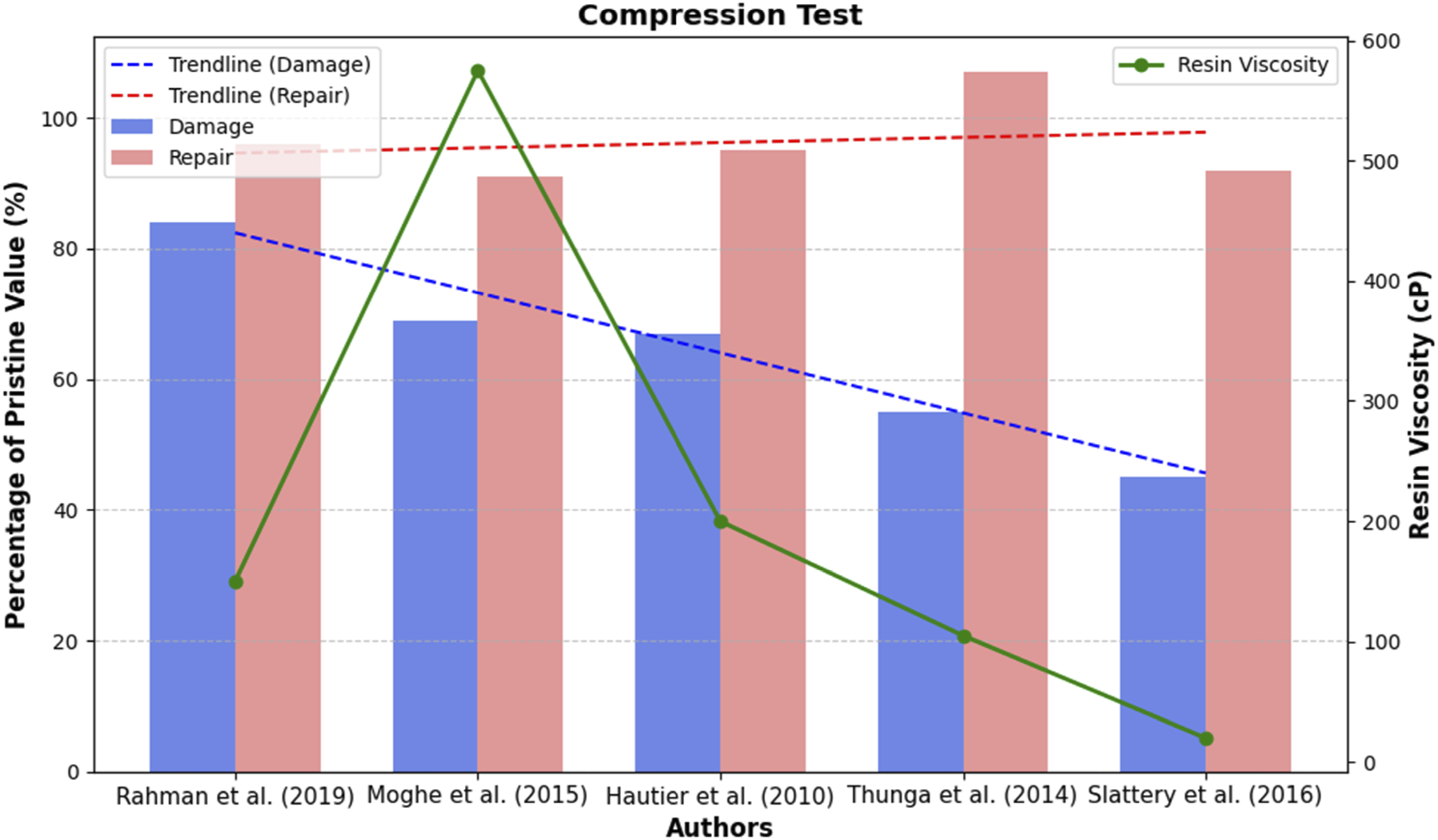
and Mode II,48,50 using a double cantilever beam and end notched flexure (ENF) test, respectively. Typical representation of a resin injection system illustrating the damage site, drilling of holes, and resin inflow. Selected process parameters of resin injection repair from various studies in the 21st century. C: compression; T: tension; B: bending. aThe result is shown as a percentage, comparing the damage to the repair relative to the pristine condition.

Slattery et al. 43 showed that the capacity of the resin to restore a certain level of strength depended on the type of loading in the test. The authors demonstrated that using cyanoacrylate CA406 resin could restore the compression and bending strength of the damaged structure, with 92% and 101% recovery, respectively. However, it did not provide much improvement in tensile strength. A compression test was also conducted on a larger coupon, with no significant recovery observed, highlighting the need to validate the recovery rate of the damaged structure based on design criteria or area of usage. The undamaged larger specimen failed 26% below the original coupon, suggesting the effect of anti-buckling constraints during compression testing. Hautier et al. 48 recommended using resins with toughness properties similar to the original structure, following the outcome of their fracture test with RTM6 epoxy. A compression after impact test was conducted, with 95% of the initial strength restored, to better understand the structural behaviour of the repaired coupon.
Kwak et al. 4 reported that resin injection restored a coupon under flexural load (three-point bending) to 93% of its original strength. The authors demonstrated an out-of-autoclave procedure, curing at 25°C for 5 days using EA9396 epoxy. The repair method resulted in a 42 µm increase in the thickness of the repaired coupon, but the interlaminar failure occurring after bending failure indicated good adhesion. Rahman et al. 46 developed an in-house device for injecting Epo-Tek 301 resin through a blind inlet hole under low pressure. Compression strength of 96% was recovered using this device; however, only a small amount of resin flowed into the crack at the bottom surface. Pourdadash Fardnam et al. 49 demonstrated the use of the injection method in repairing glass fibre cross-ply laminate subjected to buckling. Acoustic emission and wavelet methods were used to monitor and calculate the failure mechanism of the structure, respectively. The results showed that the repair restored 92% of the original structure’s compression strength.
Thunga et al. 47 investigated the influence of laminate thickness (using 24 and 32 plies) and damage type (using static and impact) in assessing the repair efficiency of the injection method. Using the same repair process, they found that the 24-ply laminate achieved higher recovery compared to the 32-ply, which may suggest that the injection parameters (such as the number of holes and infiltration time) are specific to the laminate architecture or layup. Similarly, the damage simulated by impact resulted in random cracks compared to the more well-connected cracks obtained from static loading. The random cracks may have created isolated regions that were not filled during the repair process. Overall, a compression strength recovery of 107% was achieved in the 24-ply bismaleimide carbon fibre panel repaired with bisphenol E cyanate ester resin. Moghe et al. 44 analysed the effect of energy levels used in creating delamination, comparing impact damage at 23.5 J (low energy, barely visible), 35 J (medium energy), and 51 J (high energy). The results showed that the repair could restore compression strength for all damage levels but could only restore tensile strength for the 23.5 J impact, where fibre breakage was absent. Compression and tensile strength recoveries of 91% and 78%, respectively, were recorded for the low energy impact.
Bleay et al. 51 explored the approach of “self-repair,” where damage is automatically repaired using pre-existing resin within the structure. The resin is placed in a hollow container, which also serves as structural reinforcement, and breaks upon impact, allowing the resin to flow to the damaged area. The challenge with this approach is that damage may occur in a different location from the resin container, leading to poor infiltration and minimal compression strength restoration. The authors suggested using micro-encapsulated resin particles instead of filling the resin in long hollow tubes.
Damage simulation
Laboratory delamination for injection repair was typically simulated as ≤ 50 mm in size using any of the following approaches: (a) inserting Teflon film in the midplane of the coupon before curing,4,49 (b) quasi-static indentation,46–48 or (c) impact loading using a drop weight at different energy levels.43,44,47,48 A recent study simulated delamination using Mode II fracture to replicate the delamination experienced in in-service aircraft, which typically occurs in multiple layers through the thickness and is not always well-connected. 50 The challenge with impact as a method of damage simulation is its inconsistency in reproducing delamination across multiple experimental procedures, whereas quasi-static indentation (QSI) offers better reproducibility.52,53 The most frequently used damage assessment methods in experimental studies were ultrasonic (C-scan), infrared thermography, and X-ray computed tomography (CT).54,55
Repair process parameter
Drill depth
The holes were commonly drilled to the damaged surface,4,48,49 67% through, 46 or 75% through the laminate thickness.44,47 Another study considered a drill depth between 80% and 90% of the laminate thickness.56,57 However, Russell and Ferguson 57 had to reduce the drill depth after applied pressure on the inlet hole caused the bottom surface of the coupon to crack open. A test conducted by Massey 50 showed that increasing the drill depth from the damage site to within the last two layers of the laminate enhanced fluid flow within the delamination. Slattery et al. 45 used a (100%) through-hole depth for their repair.
Inlet holes
Most studies considered using one inlet hole,44,46–49,56 with diameters ranging from 1 mm 4 to 3.5 mm, 56 typically drilled from the top of the coupon. Russell and Ferguson 57 explored using 6 to 8 inlet holes drilled around the fastener hole for the hole plate shear test. Similarly, Russell et al. 58 considered drilling holes for impact tests from the bottom surface of the coupon or direct injection through the opening where there was fibre breakage without drilling additional holes. Asiliskender et al. 59 proposed six inlet and three outlet holes, grouped on either side of the coupon with one inlet hole at the centre, for optimal flow based on the results of their computational simulation.
Vent holes
The number of vent holes depends on the orientation of the ply.
48
Four to six outlet (or vent) holes were commonly drilled circumferentially around the periphery of the delamination,
13
referring to Figure 6(a), with diameters of approximately 1 mm.56,60 However, drilling one or three vent holes in a vertical line was reported in References 49 and 4, respectively. It is important to note that in both cases, where one and three holes were used, the same method of damage simulation was employed, involving the insertion of Teflon film at the mid-plane to create a well-connected and non-circular delamination, as shown in Figure 6(b). Vent holes: (a) Drilling around a circular delamination and (b) drilling along the vertical line of the coupon.
Repair capability
Resin property
Summary of key attributes of injection resin systems used in the literature.

Surface preparation
The effect of surface contamination on the load-carrying capacity of damaged and repaired structures has been investigated in several studies.45,50,60 Results from ultrasonic C-scans by Russell and Bowers 60 showed that contamination within a delamination can potentially reduce the image size. Massey 50 investigated the use of methyl isobutyl ketone (MIBK) solvent cleaning and helium-oxygen atmospheric plasma treatment to flush out fluid ingression within the delamination. While solvent cleaning with air blasting is often used for debris removal and surface decontamination,46,47 using atmospheric plasma treatment for surface preparation can enhance wettability, surface energy, and chemically activate the surface for adhesion. 28 Adhesion failure would indicate a deficiency in surface preparation, where the injected resin failed to react with the original resin. 63 Slattery et al. 45 considered surface preparation, but it was to assess the effect of flushing uncontaminated coupons with acetone. It is advisable to include drying cycles for damaged structures before performing any repairs to prevent further damage during curing due to liquid ingress. 18 Russell and Bowers 60 considered a drying cycle of 4 h at 121°C.
Flow capability
The flow characteristics of a resin are as critical as its mechanical properties and curing behaviour. The flow potential for a repair depends on the size of the delamination, repair procedure, and applied pressure, with a required flow potential of around 50,000 Pa−1 for a viable repair.
64
Smaller delamination and thicker laminates experience greater flow resistance, as the opening of the delamination is directly proportional to its diameter and inversely proportional to the laminate thickness. However, the opening is not usually influenced by the injection pressure. The time taken to infiltrate the delaminated area depends on the injection pressure, the distance travelled, and the flow resistance, as expressed in equation (1), assuming the resin radially flows outward, with the time to fill (Tf) limited by the resin’s pot life.64,65 Most commercial resins used for hand layup do not have the required flow capacity to infiltrate delamination due to their high viscosity, unless they are formulated as infusion-grade resins, which typically have a viscosity between 200 and 500 cP at 20°C.
66
Similarly, paste adhesives (such as EA9394 and EA9396), as used in some studies, have a higher viscosity compared to infusion epoxies, as shown in Table 2. Earlier reports on injection repair noted that the recommended resin and the steps provided in the structural repair manual did not always work.
64

Repair efficiency
The repair efficiency is often represented as the percentage of the repaired strength relative to the pristine strength
67
(see equation (2)). Thunga et al.
47
reported the efficiency of a repair using equation (3), which essentially represents the ratio of the repair increment to the damage reduction. However, based on our understanding, this method does not fully capture the true state of the repair, particularly regarding scalability. As shown in Figure 7, samples 1 and 2 both have the same state of repair but different repair efficiencies (100% and 76%, respectively, using method 2). Equation (4), which takes a more conservative approach to scale experimental results for practical estimation, implies that if the repair process is used under the same conditions, it will restore a damaged specimen from any peak load to the same recovery state of 50%. Comparison of repair efficiency for different residual strengths using the same repair procedure.


Under the allowable safety margin, bonded repairs are only permitted on damaged primary structures that retain a residual strength above a certain threshold.
32
To restore a damaged structure (which should not have fallen below 67% of its original strength) to its full capacity, achieving a repair state of 33%, as determined by Method 3, is considered desirable based on our reasoning. This method measures the percentage change in the system as a ratio of the repair’s improvement from the damage to the original condition over time. It is worth noting that, in recent studies, only a few experimental results43,47 have shown improvements in compression strength exceeding 30% compared to the damaged (unrepaired) structure (see Table 1, Column 9 and Figure 8).
In equations (2)–(4),
Despite the increasing compressive strength knockdown observed across studies, the trend in strength recovery, or repair efficiency, appears to be rising, as shown in Figure 8. Repair efficiency is calculated as the percentage of strength restoration relative to the pristine value, minus the percentage of damage to the pristine. This result is unexpected, as repair efficiency would ideally decrease over time since the material becomes less capable of regaining its original performance characteristics after damage, particularly if the repair procedure remains unchanged. However, since repair procedures, materials, composite layups, structures, and experimental setups vary between studies, a comparative analysis of knockdown dependence and repair efficiency within the same study or by the same author would be valuable, as illustrated in Figure 7 with method 3. Similarly, based on available data in the literature known to the authors, Figure 8 does not show a clear correlation between the percentage of strength recovery and resin properties. It is important to note that the viscosities provided in Table 2 represent the original values given by the manufacturers at working temperatures, prior to any modifications made by the authors.
Resin injection repair – infiltration
Presently, there is no standard procedure or best practice for injecting resin into damaged areas. Most resin injection methods rely on previous results, trial and error, experience, or basic rules of thumb.43,59 The final process adopted is usually based on a series of tests that explore different combinations of the injection process (such as the use of vacuum only, vacuum with pressure, application of heat, etc.,) and parameters (such as the number, location, depth, and diameter of holes) until the best infiltration result is achieved.56,57 Given that crack openings are typically less than 10 µm in practice, the specific method of resin infiltration varies according to the coupon’s geometry and the extent or nature of the damage.64,65
Hole plate shear (HPS) was chosen to evaluate resin infiltration, as it provided suitable results for resin flow and offered insights into the repairability of delamination under high interlaminar shear stress.
64
The method of damage simulation was similar to quasi-static indentation, except that a hole was bored in the middle of the coupon before creating delamination8,62,64,68 (see Figure 9). The coupon was loaded under displacement control until a drop in load was observed, resulting in multilayer delamination with cracks extending outward from the fastener hole.
65
This method was utilized by Russell et al. following reports of delamination around fastener holes on the trailing edge of some CF-18 wing panels.58,64 Hole plate shear test for simulating delamination around a fastener hole in the laboratory.
To achieve better resin infiltration results, both the damaged coupon and resin were heated simultaneously.48,60 Heating the coupon during the repair process ensured that the reduced viscosity of the resin was maintained throughout the repair cycle. 47 While Dehm and Wurzel 56 suggested heating the coupon slightly above the resin at 60°C and 40°C, respectively, Thunga et al. 47 heated the coupon to 70°C, below the resin’s temperature of 100°C. Resin infiltration, as conducted by Russell et al., followed a two-step process: pre-injection and injection.
The pre-injection process involved: (a) drying the laminate at 105°C after applying a suitable solvent or liquid for decontamination, followed by air blasting to remove debris and potentially reconnect the crack, and (b) applying a vacuum to remove air trapped within the delamination,31,58,65 referring to Figure 10(a). After the pre-injection stage, the resin was injected using vacuum-assisted or pressure-assisted methods.
60
Post-repair, some samples were sectioned to assess and observe the cross-section using metallographic techniques.
62
Autoclave process with resin injection using vacuum only: (a) Pre-injection stage with delamination evacuation (b) resin injection using vacuum only (c) resin penetration and curing in the autoclave under maintained vacuum, pressure, and heat.
Vacuum-assisted injection
Before the pre-injection process, a leakage test was conducted using compressed air at 500 kPa. 65 In this injection method, no additional inlet or outlet holes were drilled on the structure, except for the existing fastener hole.11,60 The edges of the coupon and the bottom of the fastener hole were sealed based on the results of the leakage test, and the coupon was then placed in a vacuum bag. Air was evacuated, and the resin was gradually drawn into the fastener hole under differential pressure created in the vacuum chamber at 29 inHg, referring to Figure 10(b). Afterward, the coupon was placed in an autoclave, where a pressure of 550 kPa (≈80 psi) and heat (ramped at 0.55°C/min to 140°C) were applied simultaneously for 2 h to ensure complete penetration of the resin into the delamination and curing, referring to Figure 10(c). The presence of resin in the top of the fastener hole, left unsealed during curing, prevented air from entering the crack. This method achieved over 90% infiltration success, indicating that nearly all cracks were open to the fastener hole, with unfilled cracks likely being isolated. The results before and after the repair were compared, and notably, the fastener hole was redrilled after the repair process to ensure that the restored strength was influenced solely by the resin within the delamination.58,65 The resin frontal position was monitored by conducting the flow test in an ultrasonic immersion tank, measuring its progression into the delamination over time.59,64 This method is particularly desirable for off-aircraft maintenance or experiments involving well-linked cracks, such as delamination simulations using Teflon release film.
Slattery, McCarthy
45
also used vacuum alone to inject resin into five holes that penetrated the coupon’s thickness, with no vent holes, as shown in Figure 11. This was done after compressed air was blown into the damaged area through the holes to remove particles created by the drilling process. The resin flowed vertically through the inlet holes under a vacuum pressure of 29.5 inHg while filling the cracks horizontally through capillary action. Once the holes were filled, the syringe was removed, and the coupon was left under vacuum at ambient temperature for 24 h. Afterward, the coupon was removed from the vacuum bag and cured in an oven at 90°C for another 24 h. The contraction of the vacuum bag against the base plate due to pressure may have contributed to the quality of the re-bond, while also possibly realigning the plies at the bottom. Repair results using cyanoacrylates (CA406) resin on coupons impacted at 10 J, 20 J, and 30 J showed that the 10 J impact had the lowest repair efficiency, despite the smallest reduction in compressive strength. The authors noted that the 10 J impact created small-sized delamination that may not have been linked to the inlet holes and were closed under vacuum application. Notably, CA406, which has a low viscosity of 12–22 MPa·s and no toughening particles, was chosen after initially trying CA435, which has a viscosity of 100–250 MPa·s (see Table 2). Resin injection using vacuum only through a thickness hole.
Hautier et al. 48 discovered voids in coupons repaired using only vacuum, suggesting that additional pressure during injection may improve resin flow. Massey noticed increased porosity within the structure with a higher percentage of acetone mixture and addressed it by holding the coupon at room temperature for 5 days before curing. This allowed the acetone to extract bubbles or gas from the resin. 50 Thunga et al. 47 degassed their resin mixture for 20 min to remove air bubbles after stirring for 10 min with a magnetic bar.
Pressure-assisted injection
This method, referred to as ‘flow-through,’ was used for on-aircraft repair where disassembly was not feasible. The pre-injection process was conducted without the prolonged use of vacuum to remove air trapped within the delamination, as this could potentially draw in air through the inaccessible rear side. A leakage test could not be conducted because it was impossible to maintain a vacuum around the entire component. This method utilized the drilling of inlet and outlet holes. Low-viscosity resin without the curing agent was forced through the inlet holes, as depicted in Figure 12, under a pressure of 100 psi, with a heating blanket placed over the laminate throughout the repair cycle. Simultaneously, air escaped through the outlet holes. Notably, a vacuum was not applied to the outlet holes to remove air or draw out resin but rather to hold the device onto the structure’s surface. The vacuum between the O-ring and the outer seal created a clamping force needed to sustain the injection process under high pressure. Infiltration of the resin into the damaged area was often unsuccessful until the injection pressure was increased, and the correct combination of injection parameters (hole size, number, depth, location) was established through testing. Another challenge with this method was resin flow out through the back surface instead of into the delamination, particularly when the damage was extensive or the area was inaccessible for sealing.57,64 Resin injection device used for on-aircraft repair.
Russell and Bowers discovered that applying heat simultaneously with pressure reduces the presence of voids five times more than injecting resin under pressure at room temperature and then applying heat (while curing at atmospheric pressure). The test results also suggest that the simultaneous application of heat and pressure can withstand a higher failure load compared to applying pressure first and then heat. 60 An investigation into the influence of temperature on resin infiltration showed that applying heat during the repair cycle is critical to successful infiltration. 62
Vacuum and pressure-assisted injection
Unlike the methods described earlier by Russell et al., Dehm and Wurzel utilized vacuum and pressure-assisted injection in their work. This method involved using pressure to force resin into a blind inlet hole with a 3.5 mm diameter, while vacuum was applied to each of the four outlet holes to aid in spreading the resin within the delamination, all while applying heat simultaneously (see Figure 13). As soon as the resin flowed through the outlet holes, the injection process was stopped, and the coupon was cured at 80°C for 2 h.
56
Resin injection using vacuum and injection pressure with blind holes.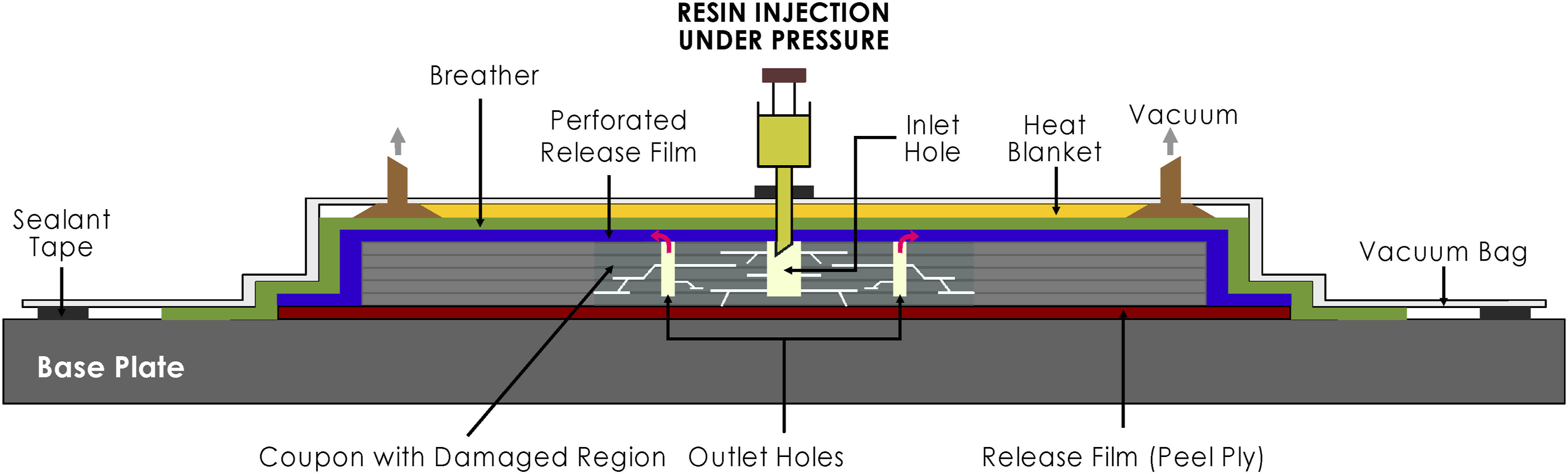
Thunga et al. also considered a similar approach for their repair process. The vacuum application removed air trapped within the delamination and assisted with resin infiltration. Once the required temperature and pressure were achieved, the vacuum ports were shut, and the resin was drawn in through the inlet hole under a constant pressure of 30 psi for 10 min. 47 Russell and Bowers 65 used vacuum and injection pressure during initial trials for resin flow. A vacuum of 29 inHg was applied to remove air while gently drawing resin into the hole. Once the hole was filled, the vacuum process was stopped, and a pressure of 172 kPa (≈25 psi) was applied to assist in resin penetration within the delamination.
While both vacuum-assisted and vacuum and pressure-assisted methods involve pressure (specifically gauge pressure with vacuum), vacuum-assisted injection refers to the application of vacuum to the outlet/vent holes to extract air, allowing the resin to flow into the delamination cavity through the inlet under a natural ‘suction’ effect or pressure difference without any external push or additional force. In contrast, vacuum and pressure-assisted injection involves applying vacuum to the outlet hole to extract air while simultaneously forcing or pushing resin into the delamination area through the inlet hole using compressed air.
The significant factors that contribute to the successful infiltration of resin injection are: 1) resin viscosity, 2) curing time, 3) applied injection pressure, and 4) the size and permeability of the delamination.
50
The variables influencing resin infiltration are further described by Darcy’s law, as expressed in equation (5).
66
Although viscosity is important, it should not be the overriding factor.
64
If the resin can adequately fill the damaged area, there is a higher likelihood of improved repair efficiency.
67

Challenges and future research
Although resin injection is not a new concept, especially in civil applications such as concrete repair, its use in the aerospace industry has evolved significantly over the past three decades, with increasing consideration and exploration of its potential as a structural repair method. Based on the review of previous studies, it is important to address some general misconceptions, as understood from our perspective: • A Teflon insert was often used to create artificial delamination,
4
simulating voids created during the manufacturing process. However, it is important to simulate near real-life scenarios that best predict actual in-service damage for which the proposed repair procedure will be utilized. It should be noted that the results of the repair may be significantly influenced by the nature of the damage.
47
Teflon-created delamination is usually not complex and well-linked, allowing easier resin flow. Composites are more sensitive to impact damage,
49
which creates very scattered cracks, and as such, a more robust repair process should be developed for such damage to maintain an airworthy aircraft. Additionally, the process of removing the Teflon film before injecting the resin was considered to have significantly altered the failure load results of the damaged (unrepaired) structure.
4
• The type of non-destructive test chosen for damage detection must be carefully selected, keeping in mind their individual limitations to achieve the best results depending on the type of scan or outcome desired. While the ultrasonic C-scan effectively detects delamination between plies, it does not provide an accurate prediction of interlaminar matrix cracks, which are better revealed using X-ray CT.
69
As such, researchers may consider combining two or more methods to validate detection results, with the objective of increasing accuracy and sensitivity across the laminate thickness. Similarly, with advancements in non-destructive testing and technological improvements using machine learning algorithms, other platforms for damage detection could be considered, such as the Lamb wave technique with convolutional neural networks
70
or phased array ultrasonic testing with object detection networks
71
for automated defect characterization and determination. • Ultrasonic C-scans do not provide an accurate assessment of delamination within multiple layers, as the defect closest to the inspection surface is detected first, making X-ray CT a better approach. However, X-ray CT also has limitations in correctly predicting the damage perimeter.
50
A recent challenge is that the level of infiltration was often assessed by comparing before and after repair images from ultrasonic C-scans. In a particular instance, a good scan showed that resin filled the cracks in the front (or top), but it was stated that only a small amount of resin flowed into the cracks at the rear (or bottom) of the coupon.
46
There is insufficient reporting on quantifying the exact percentage of infiltration, as the repair process was often deemed complete based solely on a reduction in the delamination area.
47
• It is unclear how the level of infiltration within the delamination influences repair efficiency. In earlier reports, the damaged area was inspected to determine the level of infiltration, and the process was repeated until the area was considered fully filled.
50
High repair efficiency has usually been reported by researchers, restoring more than 93% of the original static strength for compression-after-impact tests. Interestingly, the percentage increase or margin from damage to repair is often less than 30% (see Table 1), indicating that a structure with significant damage and a serious reduction in residual strength may not experience substantial improvement from existing reported results. • The recovery rate was used as a measure of successful repair or infiltration without establishing a direct dependence between the infiltration amount and the results. In cases where the margin was high, as shown in Figure 8, Teflon film had been used to create the damage,4,49 or the resin was changed to one with a lower viscosity of 0.022 Pa·s,
45
or an amount of organometallic catalyst was added to the resin.
47
There must be a balance between improving infiltration by reducing viscosity and maintaining the structural integrity of the aircraft to ensure its airworthiness. While some authors considered in-house development of resins with specialized formulations, such as BH-011813D with a viscosity of 95 cP at 21°C11,72 and DREp resin (650 cP at 25°C),
64
other authors used well-known resins. A list of resins used in studies from 1989 to the present, along with their viscosities, is provided in Table 2. • While earlier studies focused on repairing composite structures for aerospace applications, particularly on the CF-18
57
using a resin with a viscosity of 650 cP at 25°C,
64
recent publications have also explored resin injection repairs for non-aerospace applications.
73
To facilitate resin flow, emphasis has often been placed on its viscosity without necessarily considering its long-term compatibility with the original matrix. For instance, in Massey’s work, EA9396 – a commonly used paste adhesive for structural bonding with a viscosity of 3500 cP – was diluted with 10% acetone to achieve a viscosity between 540 and 697 cP, and with 20% acetone for a range of 71.5 to 81.5 cP, aiming for a viscosity below 100 cP.
50
Massey’s target viscosity of 100 cP was reportedly based on Russell’s recommendation, whose resin had a viscosity of 650 cP at room temperature. • The repair process was often considered and reported for non-aerospace composite applications,45,74 where the regulations or requirements are not as stringent as in the aerospace industry, with an emphasis on quality and safety. Therefore, researchers had more flexibility in the process, knowing that infiltration results were based on the author’s choice of material selection and the simulated delamination size.
48
It is also important to know the actual range of delamination sizes that can be repaired by resin injection. Moreover, while comparisons are often made across various strength recovery tests or loading conditions (compression, tension, or bending), it is essential to recognize that the experimental setup including the composite material, injection process, laminate layup, and especially the resin type was unique to each experiment. • Hole plate (interlaminar) shear test was carried out with fastener holes bored at the centre of the coupon. After the repair, the hole was redrilled before conducting further tests to allow for a proper comparison of the before and after repair results.62,64 However, in recent times, the resin is often left inside the inlet and vent holes drilled for inflow and suction, respectively. It is unclear what influence the resin in the holes has on the overall repair efficiency compared to the resin actually required to flow into the cracks and re-bond the delaminated area. • It was postulated in References 31 and 48, depicting the injection of resin from the top and exit/outlet from the bottom, based on the works of Russell and Bowers.
64
On the contrary, inlet and outlet holes were not explicitly stated to have been drilled from opposite sides of the coupon, which, if true, would change the dynamics of the injection process regarding the flow rate. Rather, injection was considered from the bottom (rear) surface, opposite the surface where damage (using an impactor or drop weight) was initiated, because an opening was created from fibre breakage due to the high-impact damage.
58
Similarly, there appears to be a conflict between Slattery et al.
45
and Russell et al.
65
regarding the effect of capillary action on the flow process. While the former attributed the horizontal flow of resin into delamination to capillary action, the latter noted that the effect was negligible based on the result of their resin flow test. • Injection repair was also reported for assessing the restoration capacity of bearing strength of damages created around the fastener hole.
11
Although high strength recovery was attained, it is important to note that the process did not simulate edge or enclosed delamination within the composite structure but rather addressed minor defects around the fastener hole, which, in practice, can be caused by frequently changing or overtightening the fastener. Although the damage and repair process are valid, such a procedure should not be directly transferred to the repair of other types of damage, such as impact. • An autoclave and an oven are often used interchangeably for curing, but they operate on different principles despite both curing composite specimens at high temperatures. While the autoclave operates under high pressure in addition to elevated temperature, the oven operates at atmospheric pressure. Although recent studies have considered the use of ovens for curing,45,62 earlier works utilized autoclaves,
60
which allowed for the compression of the material being cured. This compression enables the resin to further penetrate delamination and enhances the expulsion of trapped air. However, it remains unclear what percentage of infiltration is contributed by the curing process to the overall fill, as existing studies generally evaluated conditions before and after repair, with the after-repair process comprising both manual injection and curing. • Finally, numerical simulation was conducted by Lim et al.
13
to assess the effect of drilling holes in composite structures for injection repair. While hole-to-hole interaction was not present, as the distance between the holes was more than 12 times the hole diameter, care must be taken regarding the configuration used (the number of holes, location, and depth). Delamination or matrix crack simulation was not accounted for in the model, which could have adversely affected the results by possibly connecting the holes. The simulation was reported for holes drilled through the laminate thickness, whereas most studies considered drilling blind holes. Blind holes may produce different results from through-thickness holes as they create dissymmetry and instability, especially in compression.
48
Additionally, FEA simulation was conducted by Pourdadash Fardnam et al.
49
with a cohesive zone defined. However, the material used was glass fibre, compared to carbon fibre used by more than 90% of investigators in resin injection repair. The concern is that if the model was not accounted for as a composite material in the software with the orientation of the fibres to produce the anisotropic attribute, the result may not be accurate because glass itself is inherently isotropic.
Resin injection is currently limited to non-critical applications for minor repairs where significant strength restoration is not required, partly due to incomplete infiltration. The resins most commonly recommended in structural repair manuals have poor flow capability and wettability, leading to inadequate strength restoration. 22 However, many studies have recorded significant strength recovery, even with poor infiltration within the delamination. This recovery is possible because the resin in the holes during mechanical tests acts as transverse reinforcement, preventing further crack propagation. While studies have focused on strength restoration, toughness, and quantifying the influence of contamination, there is still a need to understand how the amount or percentage of infiltration directly influences recovery. Additionally, the behaviour of repaired structures under fatigue loading still requires careful consideration and understanding, as most results have only been reported for static tests.
The Federal Aviation Administration (FAA) highlights several challenges with resin injection, including incomplete infiltration, the removal of contamination within the damaged region, and additional damage caused by the drilling process. 18 Assessing the degree of infiltration and quantifying environmental contamination without damage removal are key challenges in certifying resin injection for structural repair.8,50 One of the major challenges in practice is that delamination openings are often very narrow and poorly connected, typically appearing as dispersed cracks. This restricts the flow of resin. Integrating sensors with an automated or semi-automated injection process could allow for better control and monitoring of the flow and injection pressure in a closed system. For instance, feedback on the pressure in unfilled zones could ensure more consistent and precise filling, while resin pigmentation could improve flow visibility. Another challenge is establishing engineering standards for the injection process based on the structure’s design requirements, application, and damage type. Even if process parameters can be defined for real-time scenarios using manufacturer information on the structural composition of the damaged part, determining the actual type or cause of in-service damage remains a significant challenge. 75
Due to the current limitations of existing non-destructive inspection (NDI) techniques in detecting weak or kissing bonds, the quality of the re-bond poses another challenge. Although a proof test is recommended to validate the integrity of the bond line, 25 incomplete infiltration remains a major concern in injection repair, with resin flow and formulation being the focus of significant research over the years.42,50,65 Apart from studying and improving the rheological properties of the resin, other methods of improving the injection process should be considered. Design optimization is necessary to understand the influence of various parameters, such as the number, location, and depth of holes, as well as injection or vacuum pressure, on the overall repair efficiency of the system. Additionally, it is important to determine the influence of hydrostatic and/or capillary pressure on the entire injection process and to explore methods for measuring or quantifying the level of infiltration as a complement to images generated from ultrasonic C-scans. Further study is required to explore the compatibility of developed resins with various composite materials to ensure effective bonding and durability under different environmental conditions, and to consider the effects of degradation on injection repairs. This would help prevent the need for re-repairing previously repaired regions.
Numerical simulation of resin injection for delamination repair, aimed at analysing the performance of repaired structures under both static and cyclic loading, remains limited and challenging. Considering that resin, as a repair material, is a fluid (liquid), unlike the solid materials used in previous repair methods such as patch or scarf repair, it is essential to understand and analyse the physics behind the fluid’s flow into or within the delamination, especially in more complex impact damage scenarios. The flow capability of resin is explained using fluid dynamics principles, specifically governed by Darcy’s law, and can be numerically modelled as flow through porous media. Improving transverse or out-of-plane strength by exploring hybrid options with resin injection should be considered, and validating this approach for the structural repair of deep delamination under fatigue loading is crucial. The hybrid approach could promote the use of resin injection in primary structures to meet certification requirements for bond quality, providing the necessary transverse strength while also serving as a fail-safe mechanism.
Conclusion
This paper reviewed resin injection repair with a focus on infiltration. Critical challenges associated with resin injection are discussed, along with recent studies that highlight its potential for structural repair. Although traditionally viewed as a cosmetic repair technique, resin injection offers notable advantages over conventional methods, especially in cases where fibre breakage is minimal or non-existent, eliminating the need to remove the damaged area. Resin injection repair has been reported to restore, on average, 90% of the original structure’s compression strength. However, the effectiveness of this repair method is constrained by the severity of fibre breakage and the extent of residual transverse distortion. Achieving complete infiltration remains a significant challenge, particularly with commercial resins that have high viscosity. Successful infiltration is often accomplished using low-viscosity resins without curing agents, while optimizing the injection process and parameters. When reducing viscosity by mixing catalysts or acetone with the resin, as opposed to heating it, care must be taken to ensure the resin retains its mechanical properties to maintain the structure’s integrity and the quality of the re-bond. Therefore, assessing the damage tolerance of the repaired coupon through re-impacting is necessary. Additionally, understanding the benchmark for successful infiltration will be valuable, serving as a guide for engineers and technicians in the field, as well as for researchers before conducting experimental tests.
Footnotes
Acknowledgments
The authors gratefully acknowledge the support of the Commonwealth of Australia, represented by the Department of Defence, through a Defence Science Partnerships agreement for their collaboration with Monash University in the research of aircraft structural repairs.
Statements and declarations
Funding
The authors received no financial support for the research, authorship, and/or publication of this article.
Conflicting interests
The authors declared no potential conflicts of interest with respect to the research, authorship, and/or publication of this article.