
Abstract
The rapid development of energy storage systems has put forward higher requirements for the specific capacitance and stability of electrode materials. Conductive polymers with pseudocapacitance are very promising electrode materials due to their low cost, easy preparation, easy chemical modification, light weight, and good flexibility. However, supercapacitors based on conductive polymers still have disadvantages such as limited capacitance, low energy density, and low cycling stability. It is a promising way to blend conductive polymers with other materials to improve specific capacitance and stability. However, the preparation steps of multicomponent composites are relatively cumbersome, and preparation equipment are usually complex and costly. Therefore, it is necessary to design and synthesize conductive polymers with high specific capacitance. This review starts with the current development status of supercapacitors, focusing on the device structure, preparation methods, working principles, and important device parameters of polymer based pseudocapacitors; followed by the summary of development of supercapacitors based on thiophene based polymers.
Introduction
Energy source is a natural resource that can directly or indirectly generate a certain type of energy, and it comes in various forms. Fossil fuels such as coal, oil, and natural gas are the most widely used forms of energy source. Its non-renewable and excessive consumption have brought a serious energy crisis to humans who rely on fossil fuels, and have also made the world strongly aware of the indispensable nature of energy source. On the basis of fully utilizing existing fossil fuels as much as possible, more and more researchers are committed to exploring the utilization of clean and renewable energy sources such as solar energy, wind energy, and ocean energy. 1 However, renewable energy is instable at some point. For instance, solar energy cannot be collected at night and energy density is usually affected by various factors such as daylight duration, season, weather conditions, and so on. Wind energy, meanwhile, has volatility and discontinuity. Therefore, it is necessary to effectively collect, efficiently convert and store the energy generated by energy source, and then safely and stably output it. There are various ways of energy storage, among which electrochemical energy storage has attracted much attention and is leading the way in the field of energy storage due to its high conversion efficiency and convenient usage. The devices used for electrochemical energy storage mainly include batteries and electrochemical capacitors (ECs). Electrochemical capacitors, also known as supercapacitors (SCs), as a new type of device that can store high-power energy, have become a new highlight in the field of chemical power sources.2,3 It is demonstrated that supercapacitors have a very broad application prospect in multiple important fields and links such as rail transit, modern communication, aerospace, national defense and military industry, for potential energy recovery of lifting equipment, power generation, smart grid, consumer electronics, and so on.4–11
Supercapacitors are an energy storage device that firstly developed in the 1870s and made rapid progress in the 1950s. In the 1980s, the discovery of pseudo capacitive electrode materials significantly increased the energy density of ECs, and electrochemical capacitors were dubbed as true supercapacitors.
12
SCs are mainly composed of current collector, electrode, electrolyte, and separator, as shown in Figure 1(a).
12
Unlike batteries and plate capacitors, SCs are electrochemical devices that store energy through the polarization and migration of anions and cations on the interface between the electrolyte and high specific surface area electrodes. They are very suitable for rapid storing and releasing of energy.
Compared with common energy storage devices such as lithium-ion batteries and fuel cells, SCs have higher power density and longer cycle life (more than 106 cycles). It can be concluded from Figure 1(b) that 13 the energy density of SCs is in the range of 0.1∼100Wh/kg, the power density of SCs is in the range of 101∼105 W/kg. The energy density of SCs is between that of ordinary capacitors and rechargeable batteries, while its power density is lower than that of ordinary capacitors and higher than that of batteries. It fills in the gap between two traditional energy storage technologies and is an effective complementary device between two energy storage units. At the same time, SCs can also be used in extremely harsh environments such as extremely low temperature, without causing environmental pollution.
In this review, we mainly discuss the recent research activities carried out with an emphasis on the design, synthesis and properties of pseudocapacitive electrodes based on conductive polymers for EC. This review is organized into three sections: (i) overview of types and energy storage mechanism of SCs; (ii) pseudocapacitors and electrode materials based on conductive polymers; (iii) research status of thiophene conjugated polymers in supercapacitors. We aim to outline the benefits and challenges of the use of pseudocapacitive electrode materials in ECs. We also highlight the key technical challenges with the hope of stimulating further advances in research.
Overview of types and energy storage mechanism of SCs
According to the different energy storage mechanisms of supercapacitors, they can be simply divided into two categories: (1) Electric Double Layer Capacitors (EDLC); (2) Redox capacitor, also known as Pseudocapacitor (PC).
Electric double layer capacitors
The energy storage process of a double layer capacitor is shown in Figure 2(a)–(b),
14
which uses the positive and negative charge layer interface formed by electrostatic adsorption between the electrode and electrolyte to store charges. The complete charging and discharging process is as follows: the electrode is placed in an electrolyte solution, and a separator (diaphragm) separates the positive and negative electrodes into two parts. During charging, the cations in the electrolyte gather on the negatively charged cathode collector to form one charge layer, while the anions gather on the positively charged anode collector to form the other charge layer. Through electrostatic adsorption, the negative and positive ions are gathered on the electrode to achieve energy storage; During discharge, the anions and cations accumulated at the anode and cathode electrodes are released back into the electrolyte from the current collector. From this, it can be concluded that EDLC stores energy through electrostatic adsorption -desorption process of positive and negative ions, which is a physical process. Therefore, the charging and discharging processes are carried out quickly, which means that power density of the capacitor is high. In addition, as the generation of charge layer occurs on the electrode, the contact area between the electrode and the electrolyte solution is closely related to the amount of charge storage. The larger the specific surface area of the contact interface is, the more energy can be stored. Therefore, porous carbon materials such as activated carbon, carbon nanotubes, graphene, which have the characteristics of large specific surface area, high conductivity, high mechanical strength, good corrosion resistance, and high temperature resistance, have become ideal electrode materials for double layer capacitors.14–21
Redox capacitors (pseudocapacitors)
Redox capacitors, also known as pseudocapacitors, perform energy storage and release processes that occur through a series of rapid and reversible redox reactions with electrolyte ions on the surface or bulk of the electrode material, accompanied by the insertion or removal of electrolyte ions. 6 When charging, a certain voltage is applied to the two poles of the supercapacitor, and electrolyte ions are adsorbed or embedded on the surface and inside of the electrode material; When the external circuit is connected for discharge, the embedded electrolyte ions are released into the electrolyte. At the same time, in order to maintain electrical neutrality, the electrode needs to release charges, thereby forming a current in the external circuit. Due to the fact that the energy storage process of pseudo capacitors not only occurs on the surface of the electrode material, but also inside the electrode material, pseudo capacitors have higher specific capacity and specific energy than double layer capacitors, 22 and their specific capacitance is usually 10∼100 times higher than that of double layer capacitors under the same electrode area.
According to the varied places where ions perform redox reactions, pseudocapacitance energy storage mechanisms can be classified into three categories22,23: Underpotential Deposition, Redox Pseudocapacitance, and Intercalation Pseudocapacitance (as shown in Figure 2(c)–(e), respectively). Underpotential deposition refers to the process in which metal ions in a solution obtain electrons on the surface of another metal to form a adsorption monolayer. Redox pseudocapacitance is based on the process in which ions in the electrolyte are electrochemically adsorbed onto the surface or near surface area of the electrode material, accompanied by charge transfer; Intercalation pseudocapacitance is based on the process in which ions in solution can be inserted into a tunneled or layered material, leading to an oxidation-reduction reaction, while the electrode material will not perform phase transition.
Pseudocapacitors can perform oxidation-reduction reactions on the surface, near the surface, or even within the electrode materials, while accompanied by a large amount of charge transfer; for double layer capacitors, only one charge layer can be formed by electrostatic adsorption on the surface of the electrode material, causing the specific capacity of pseudocapacitors 10∼100 times higher than that of double layer capacitors.24,25 However, due to the slower charge or carrier transfer during the Faraday process compared to the electrostatic adsorption process of ions, the specific power of pseudocapacitors is lower than that of double layer capacitors. In addition, the redox reaction process is accompanied by the insertion/detachment process of electrolyte ions within the electrode material, and the electrode material structure needs to undergo repeated expansion and contraction, which can easily cause structural collapse or fracture. Therefore, the cycle life of pseudocapacitors may not be as long as that of double layer capacitors.
There are two common types of electrode materials applied in pseudocapacitance, namely metal oxides and conductive polymers. The former type usually takes ruthenium dioxide, manganese dioxide, nickel oxide as positive electrode materials, and the latter type usually take p-type or n-type or p-n type doped polypyrrole, polyaniline, polythiophene as electrodes.
Pseudocapacitors and electrode materials based on conductive polymers
Electrodes are the core of capacitors, and electrode materials play a decisive role in the performance of supercapacitors. In order to further improve capacity and cycle life of supercapacitors, it is urgent to develop new electrode materials with high specific capacity, high specific power, and high stability. Conductive polymers, which demonstrate many unique properties, such as high energy storage capacity, low price, ease of processing, lightweight quality, and flexibility, have attracted attention of many researchers, inspiring plenty applications on polymer electrodes. Among numerous conductive polymers, polyaniline (
Overview of conductive polymers
Electric conductive polymers (ECPs), also known as conductive polymers, whose conductivity usually range between that of semiconductors and conductors. Via doping or other methods, electricity can be conducted in these polymers, referring to intrinsic conductive polymers. The structural feature of these polymers is the alternation of single and double bonds on their conjugated chains, extending π-conjugated systems to a large number of cyclic building blocks, forming conductive macromolecular structures. 41 The easy flowing of π electrons in conjugated systems creates the possibility of conductivity. In the late 1970s, Heeger and MacDiarmid discovered that polyacetylene, which were synthesized by Shirakawa’s method, showed 12 orders of magnitude increased of conductivity after oxidative doping. 42 The discovery of doped polyacetylene has pushed research on conductive polymers to a climax.43,44,45 Doped conductive polymers have high conductivity, and some can even be comparable to metals. 46
The conductive mechanism of conductive polymers
The structures of conductive polymers all have π-conjugated systems with alternating single and double bonds, formed by the lateral overlap of p orbitals on adjacent carbon atoms that are not involved in hybridization. Each p orbital carries an unpaired valence electron, and multiple p orbitals are linearly combined to form a bonded π molecular orbital and corresponding anti-bonded π* molecular orbital. In the presence of appropriate oxidants, electrons will be lost in the lower energy level bonding π orbitals, forming positively charged “holes” (electron deficient parts), and the remaining electrons are more easily moved in the valence band of some “holes”, thus conducting electricity.
When conductive polymers are used as electrode materials for supercapacitors, they utilize the rapid redox reaction between their surface and near surface bulk phases, obeying the working principles of Faraday pseudocapacitors, for energy storage. As shown in Figure 3(b) and (c),
47
the larger π-conjugated systems polymers formed, the faster π electrons delocalized, thereby making polymers conductive. When a voltage is applied to oxidize the conductive polymers, the polymers will lose electrons and form positively charged holes. In order to maintain electrical neutrality, anions in the electrolyte solution will be adsorbed around the polymer chain, completing p-type doping. On the other hand, when the polymers are reduced, the conjugated chain gains negatively charged electrons, and the positive ions in solution are adsorbed, completing n-type doping. Through this highly reversible p-type/n-type doping process, accompanied by ion adsorption-desorption on the polymer surface or in the bulk phase, a whole conductive process is formed while completing the storage and release of charges, resulting in the high pseudocapacitance of conductive polymers.
Preparation of conductive polymers
There are various methods for obtaining conductive polymers, including chemical polymerization, electrochemical polymerization, photochemical polymerization, and metathesis polymerization.47,49,50 For compounds containing aromatic or heterocycles, the commonly used polymerization methods in laboratory are chemical polymerization and electrochemical polymerization.
Chemical polymerization is a method of coupling or oxidizing monomers to obtain polymers in application of transition metal catalysts or oxidants under certain solvent conditions. The commonly used metal catalysts to perform coupling polymerizations are mostly based on nickel or palladium compounds, such as bis(triphenylphosphine)palladium(II)chloride (Pd(PPh3)2Cl2), Tetrakis(triphenylphosphine)palladium(0) (Pd(PPh3)4), and so on. Oxidants such as anhydrous ferric chloride and persulfate are commonly used for oxidative polymerization.44,51 Chemical polymerization can achieve large-scale preparation of conductive polymers, though prepared polymers have the disadvantage of poor uniformity and high molecular weight distribution, leading to poor polymer solution processing.
Electrochemical polymerization can be categorized into cathodic polymerization and anodic polymerization. The cathodic polymerization was first proposed for the synthesis of poly(p-benzene) and later used for the synthesis of heterocycle polymers.48,52 The cathodic polymerization is usually applicable to prepare electrode materials sensitive to anodic corrosion, such as small bandgap semiconductors. However, the disadvantage of cathodic polymerization is that the obtained polymer is in a neutral state and often has poor conductivity.
Anodic polymerization is a process in which monomer molecules lose electrons and undergo oxidation under a certain applied voltage, resulting in free radical polymerization on the electrode surface to obtain conductive polymers. The reaction is usually carried out in a one chamber three electrode system, as shown in Figure 3(d). 48 Compared with chemical synthesis and electrochemical cathodic synthesis, anodic oxidation polymerization has obvious advantages: (i) no catalyst is required; (ii) doped conductive polymers can be directly obtained on the electrode surface after polymerization, namely in situ polymerization (particularly useful for electrochemical applications); (iii) the thickness of polymer film or the mass of polymer can be controlled by electrical quantity; (iv) possibility of in situ characterization of growth processes or polymers through electrochemical and/or spectroscopic techniques; (v) continuous polymerization and deposition can be carried out.48,52 Therefore, anodic oxidation polymerization is more suitable for polymer thin film electrodes, thin layer sensors, microdevices. 53
The quality of the polymer film obtained by anodic polymerization can be controlled by the quantity of electric charge consumed during polymerization process, which can be calculated by the following formula, and it should be noted that the premise of the formula is to assume that the Coulombic efficiency of the electrochemical process is 100%.54,55,56

In formula (1), Wp represents the mass of the polymer film deposited on glassy carbon electrode, η represents the current efficiency (assumed to be 100%), Qdep is the total charge during polymerization process (C), M is the molar mass of the monomer (g/mol), F is the Faraday constant (96485 C/mol), Z represents the number of electrons transferred on each monomer unit forming the polymer, where Z = 2 + f,57–59 f represents the doping level, their values are generally between 0.2 and 0.3 due to different precursors.60,61
Assemble of pseudocapacitors based on conductive polymers
Conductive polymers can be categorized into n-type doping and p-type doping types. When act as electrode materials, different doping type of conductive polymers can assemble three forms of pseudocapacitors, namely Type I, II and III pseudocapacitors.44,48
Type I pseudocapacitors
Type I pseudocapacitors are composed of two identical p-type doped conductive polymers as positive and negative electrodes, respectively. Because most conductive polymers are p-doped, the configuration of Type I supercapacitors are the most common ones, which are basically based on polyaniline or polypyrrole working as electrode. When Type I pseudocapacitor is charged, the capacitor and positive electrode are in completely p-doped state, while the negative electrode is in non-doped state (neutral state); During discharge, the positive electrode p-doped polymer is reduced, and the negative electrode neutral polymer is oxidized. At this time, both poles are in a semi doped state, while the voltage difference is zero. At this point, it can be concluded that Type I supercapacitor can ultimately discharge only half of the stored electric charge. Therefore, this type of pseudocapacitor has a low specific energy and a small voltage difference (about 1.0 V) between the positive and negative electrode.
Type II pseudocapacitors
The positive and negative electrodes of Type II supercapacitors are composed of two different types of p-type conductive polymers, with different electrode materials and different potential ranges of the devices. Type II supercapacitors have a wider working potential range (around 1.5 V) during charging, which is beneficial for improving specific energy; when the voltage difference is zero after complete discharge, the doping rate of the positive electrode storage charge exceeds 50%, resulting in a higher specific capacitance for the capacitor.
Type III pseudocapacitors
When two conductive polymers that can be both n-type and p-type doped are used as positive and negative electrodes for charging, the positive electrode is completely p-type doped, and the negative electrode is completely n-type doped. The voltage difference (about 3.0 V) is greater than that of Type II capacitors; during discharge, the positive and negative electrodes can be completely doped, and the stored charges during charging process can be fully released. This means that Type III pseudocapacitors can be fully charged or discharged during charging and discharging process. In that case, Type III pseudocapacitors can not only have high energy storage capacity, but also keep both electrodes in a high conductivity doped state, thereby reducing the internal resistance of the capacitor and increasing its specific power.
Performance for three different types of pseudocapacitors assembled by conductive polymer poly-3-(4-fluorophenyl)thiophene. 44
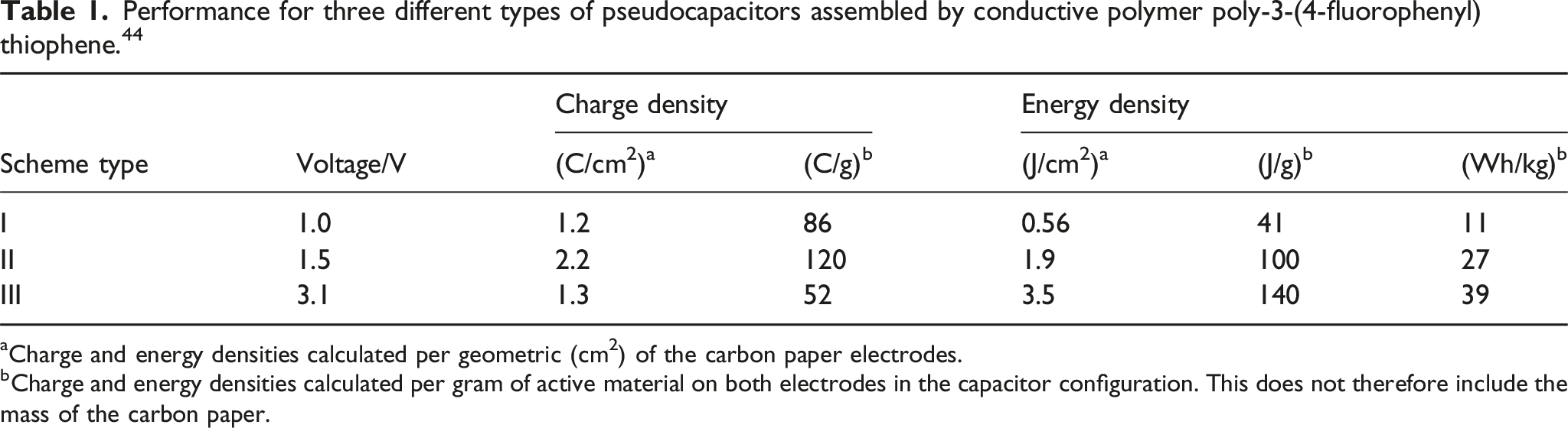
aCharge and energy densities calculated per geometric (cm2) of the carbon paper electrodes.
bCharge and energy densities calculated per gram of active material on both electrodes in the capacitor configuration. This does not therefore include the mass of the carbon paper.
Performance characterization of electrode materials and supercapacitors
The performance of pseudocapacitors can be systematically characterized by a series of parameters such as capacitance, working voltage, equivalent series resistance, energy density, power density and so on, as shown in Figure 4.62,63 Multiple instruments, testing methods, or modes have been developed and applied to characterize the electrochemical performance of pseudocapacitors, among which the most commonly used tests include cyclic voltammetry (CV), constant current charge/discharge (CCCD), and electrochemical impedance spectroscopy (EIS).
Cyclic voltammetry test
Cyclic Voltammetry (CV) is a testing method that applies a voltage to an electrode material as a triangular wave excitation signal changes over time. Within a certain voltage range, it records the response current changes of the electrode material with a constant cyclic change of applied voltage. CV curve is one of the necessary means for characterizing the performance of supercapacitors. It not only provides valuable information related to testing the electrochemical performance of electrodes (reversibility, reaction kinetics) to qualitatively determine the steps and mechanisms in the electrochemical process, but also can be used to quantitatively calculate the specific capacitance of electrode materials, based on the following formula2,56,61:
In formula (2), E1 and E2 are the potential windows during the cyclic voltammetry testing process, where i(E) represents the timing current, and
Due to the fact that EDLC electrode materials store energy through electrostatic adsorption, the specific capacitance of the material is independent of the applied potential, so the shape of corresponding cyclic voltammetry curve is very similar to a rectangle, as shown in Figure 5(a). However, in the actual cyclic voltammetry testing process, due to the fact that the adsorption-desorption process of electrolyte ions on or near the surface of the electrode material takes time to complete, the actual curve obtained may slightly deviate from the rectangle, as shown in Figure 5(b). Pseudocapacitive materials store charges through an oxidation-reduction reaction process. Therefore, when the applied voltage reaches the oxidation potential of the electrode material, the response current will sharply increase, forming oxidation and reduction peaks on the curve. In addition, by comparing the changes in the shape of the cyclic voltammetry curve under gradually increasing scanning rates, the rate performance of the electrode material can be intuitively judged. As shown in Figure 5(c), while the curve can remain a rectangle shape at high potential scanning rate, the electrode is able to exhibit high rate capability. This is mainly because at high potential scanning rate, if the anions and cations in the electrolyte cannot complete the adsorption and desorption reactions that occur on the electrode surface in time, resulting in deformation of the CV curve.
66
The CV curve shape obtained from multiple cycles of scanning electrode materials at a certain scanning rate can also be used to characterize the cycling stability of supercapacitor electrode materials or devices, which usually showed better stability with smaller change in CV curve. (a-c) Illustration of CV test principle: (a) ideal CV curves of typical EDLCs; (b) actual CV curves of EDLC
62
; (c) CV curves of pseudocapacitors
63
; (d) Illustration of the GCD testing in three-electrode system
6
; (e) Illustration of the Nyquist
64
plots of EIS of supercapicitors; (f) Illustration of the Bode
65
plots of EIS of supercapicitors.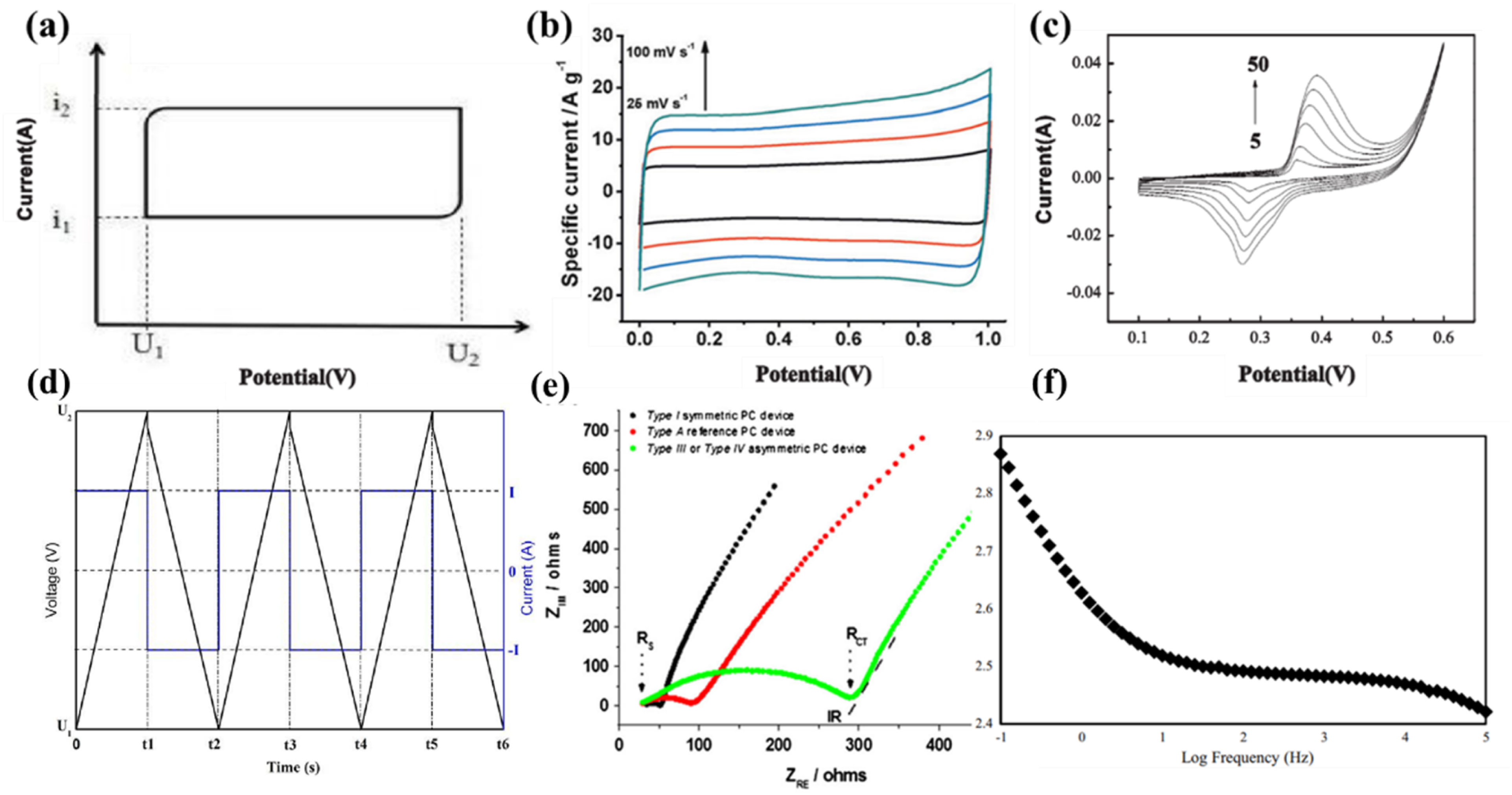
Constant current charging and discharging test and cycle stability test
The constant current charge discharge test, also known as the Galvanostatic Charge Discharge (GCD) method, is based on the principle of applying a constant charge/discharge current signal to the test electrode to record the potential changes over time during the charging or discharging process of the electrode material within the set voltage range driven by this current. The charging and discharging curves of a typical double layer capacitor are completely symmetrical straight lines which are forming an isosceles triangle with the horizontal axis, as shown in Figure 5(d). GCD is also an important method to characterize the energy storage properties of electrode materials. It can not only be used to calculate the specific capacitance value and Coulombic efficiency of electrode materials during the electrode process, but also to characterize the cycling stability of electrode materials. The formula used to calculate the electrode specific capacitance and Coulomb efficiency using GCD testing is as follows
67
:

In formulas (3) and (4), Cs (F/g) represents the specific capacitance of the electrode material, I (A) represents the charging and discharging current, tc and td (s) correspond to the charging and discharging times, ΔV (V) represents the potential difference, and m (g) is the mass of the active substance coated on the working electrode.
In constant current charging and discharging tests, the specific capacitance of the corresponding devices or materials can be reflected via voltage changes over time. The cycling stability of materials and devices can also be intuitively demonstrated by this test, which indicates more commonly applicated than cyclic voltammetry.
AC impedance testing
AC impedance testing, also known as electrochemical impedance spectroscopy (EIS) testing. A small amplitude sine wave potential is applied to the electrode material as a disturbance signal, recording the impedance value, phase angle, and frequency changes of the electrode material over a large frequency range and a long time span. Due to the wide frequency range of EIS measurement, more information related to the interface of electrode materials can be obtained through this test, such as contact resistance, charge transfer resistance, diffusion resistance, and time constant. It is a powerful tool for analyzing the interface process of electrodes, quantitatively analyzing rate constants, ion or electron conductivity, and electrical double-layer capacitance parameters. It is also an important means for characterizing the electrode performance of supercapacitors,68,69 It is an electrochemical method for steady-state measurement. The test results of EIS are usually expressed using Nyquisit 64 and Bode plots, 65 as shown in Figure 5(e) and (f).
Figure 5(e) shows the Nyquist curve of
The Bode curve mainly reflects the impedance variation of supercapacitors with changing of test frequencies. As shown in Figure 5(f), by increasing the frequency from 0.1 Hz to 100 kHz, the impedance of graphene supercapacitor was decreased from 740 to 264 Ω.
Energy density and power density
Among the performance indicator systems of various energy storage and conversion systems, power density and energy density are the most directly related parameters to the final practical application, therefore they are the most commonly used in capacitor performance evaluation. The efficiency of energy absorption and transportation is usually described in terms of mass (W/kg) or volume power (W/cm3) density, and the energy that can be stored or transported is expressed in terms of the corresponding mass (Wh/kg) or volume (Wh/cm3) energy density. In order to effectively compare the performance of different electrochemical energy storage devices, most literature presents and comprehensively evaluates the overall performance of energy storage devices in the form of Ragone diagrams (energy density versus power density).
It should be noted that energy density and power density can only be used to characterize the devices of supercapacitors, rather than the performance of individual electrode materials. The values of power density and energy density can be calculated from the data of constant current charging and discharging, and the calculation formula for energy density is:
In this formula, C is the specific capacitance (F/g) of the supercapacitor, V1 and V2 are the termination potentials during the charging and discharging process, and the difference between the two is the working window of the supercapacitor. When V1 of a double layer capacitor is 0, or the charging and discharging curves of a pseudocapacitor are completely symmetrical, the corresponding energy density formula is:
The value of power density P (W/kg) is calculated according to formula (7) below, where E is the energy density (Wh/kg) and t is the discharge time (h):
In this article, the energy density (P, W/kg) and power density (E, Wh/kg) of Type III symmetric capacitors are calculated by applying formulas (6) and (7) with slight modifications to obtain (8) and (9), respectively.

In the formula, Cs (F/g) refers to the specific capacitance, ΔV (V) is the potential difference, and td (s) refers to the discharge time.
Research status of thiophene conjugated polymers in supercapacitors
Polythiophene, as an important pseudocapacitive electrode material, has a high theoretical capacitance of 485 F/g, 3 a wide potential window of 1.2 V, 27 and high chemical and thermal stability. It is synthesized from inexpensive raw materials via simple preparing methods, making it one of the promising electrode materials for supercapacitors. Polythiophene can be doped with both n-type and p-type dopants, so capacitors assembled from polythiophene may have a high open circuit potential, which may store more energy. However, the n-type doping process in polythiophene often occurs at a voltage with a negative potential, which is close to the decomposition voltage of ordinary solvents. The conductivity and specific capacitance of the n-type doping state are low, resulting in high self-discharge rate and poor equipment cycle life of the device. In order to overcome these shortcomings, molecular design and modification are widely applied to reduce the electron cloud density on the thiophene ring, narrowing the bandgap of the polymers, diminishing the possibility of polythiophene doping in oxygen, thereby improving the stability of polythiophene in air and further improving the stability of polythiophene type capacitors.47,72
Structural modification on mainchains of thiophene based polymers
One way to improve the stability of polythiophene electrode materials is to utilize the easy modification of thiophene by directly introducing substituents conjugated with the main chain at 3-position of thiophene, which can disperse charges to a certain extent and reduce the polymer band gap. Common substituents include phenyl, alkyl, alkoxy, and so on, as shown in Figure 6. Chemical structures of thiophene based polymers applied on PCs.
As shown in Figure 6, Rudge et al compared the capacitance of seven polymers, including polypyrrole (
Poly(3,4-ethylenedioxythiophene) (
Polymers based on 1,2-di(2-thienyl)ethylene can minimize the drawbacks of thiophene based electrical supercapacitors, such as irreversibly oxidization, 17 a low ratio between n- and p-doping level, 18 a region of low conductivity existing between n- and p-doped states for the polymer. 19 Modifying electron deficient functional groups in the molecular structure of 1,2-di(2-thienyl)ethylene or extending the conjugated length of polymer monomers can reduce the band gap of the polymers, thus which capacity would be enhanced.
Summary and comparison of capacitance properties of polymers in Figure 6.

aCyclic voltammograms of composite electrodes based on in 1 M Et4NBF4–acetonitrile with Ag/Ag+as reference electrode, Scan rate: 50 mV/s.
bCalculated from the charge and mass of polymer in an assembly of a positive (p-doped) and a negative (n-doped) electrodes.
cCalculated from the specific capacitance and the mean p- and n-voltage difference.
dCalculated from the specific energy and a discharge time of 10 s.
Another way to improve the stability of polythiophene electrode materials is to directly replace the carbon atoms on the thiophene ring with electron withdrawing atoms. David Curtis et al.
80
systematically studied the n-type doping performance of
The capacitance and energy density of the polymer obtained from the modification of the monomer thiophene structure above have been improved compared to polythiophene, but it is still far from meeting the requirements of electrode materials for energy storage devices. Further consideration and research are needed to obtain conductive polymer materials with higher specific capacity and energy density.
Regulation of bandgaps of thiophene based polymers
Band gap is the energy difference between the valence band and conduction band of a material. 82 The band gap of polymers corresponds to the energy difference between the highest occupied molecular orbitals (HOMO) and the lowest unoccupied molecular orbitals (LUMO) of each building block, which determines the minimum adsorption energy and excitation light energy of the material66,83,84; Meanwhile, due to the close correlation between bandgap and frontier orbital energy levels, regulating the energy levels of polymer molecular orbitals is crucial for the carrier mobility, capacitance, stability, and other aspects of polymers and their devices. 79
There is a lot of research on the preparation of narrow bandgap (Eg = 1.5-3.0 eV) or low bandgap (Eg <1.50 eV) polymers up-to-date. There are mainly two methods that can be summarized: the first one was proposed by Wudl and his colleagues in 1984, which involves introducing fused ring thiophene (such as thieno[3,2-b]thiophene, benzo[1,2-b:4,5-b']dithiophene, and so on) into the polymer skeleton to enhance the proportion of quinoid structures presented in the polymer 85 ; Another method proposed by Havinga and colleagues in 1992 is based on constructing a “donor-acceptor” type conjugated copolymers, 43 which reduces the band gap of the polymer through intramolecular interactions between the electron-deficient (“A”) monomers and the electron-rich (“D”) monomers.43,85
Application of fused aromatic structure on thiophene based polymers
Introducing polycyclic aromatic hydrocarbons onto the thiophene ring to increase the planarity of the conjugated framework and the strength of the conjugated system is effective in reducing the polymer band gap, improving carrier mobility and stability of the polymer.82,86,87,88 Arbizzani et al.
82
first studied dithiophene[3,4-b: 3′, 4′-d]thiophene, and polymerized under different conditions to obtain different electrode materials (Figure 6, polymer
Fusalba et al.
86
synthesized 4H-Cyclopenta[2,1-b:3,4-b']dithiophen-4-one (CDT) with decreased energy band gap compared to bithiophene. The polymer
Ferris et al.
88
introduced electron withdrawing cyano groups into the heterocyclic ring fused with thiophene to obtain Dicyanomethylene-4H-cyclopenta[2,1 -b;3,4-b’]dithiophene (CDM), with an extremely low band gap of only 0.8 eV due to the introduction of electron withdrawing groups, indicating that the polymer (Figure 6, polymer
Application of donor-acceptor structure on thiophene based polymers
In the design of narrow bandgap semiconductor polymers, alternating arrangement of electron donor (D) units and electron acceptor (A) units along the conjugated main chain is an effective method to regulate the energy levels and optoelectronic properties of conjugated polymers. The driving force between donors and acceptors promotes the delocalization of π electrons and the formation of quinoid structures, thereby reducing the alternating bond length and optical band gap. Moreover, the charge transfer within the photoinduced molecule is related to the HOMO energy level of the D unit and the LUMO energy level of the A unit, which also promotes the reduction of the optical band gap. 82
Most of the conductive polymers mentioned earlier can only undergo p-type doping. If they combine with electron withdrawing groups with n-type doping, they may have better charge transfer performance between donors and acceptors, and longer conjugated chains on the polymer skeleton, resulting in better charge-discharge performance. Such materials should be more suitable to act as electrode materials for Type III supercapacitors.
The D-A alternating conjugated polymer is widely used as a donor unit in the research of supercapacitors, while EDOT can act as either electron-rich or electron deficient building blocks of conducting polymers, which can be utilized as charge-storage materials because of its many favorable properties, including reduced band gap, low oxidation potential for conversion to the conducting state and high stability in the conducting form, as well as its larger electroactive potential window and higher cycling stability than Chemical structures of EDOT based polymers applied on PCs.
Summary and comparison of properties of polymer electrode materials in Figure 7.

aThe specific capacitance value of electrode material is not provided in the literature.
bThe specific capacitance value of electrode material is based on Type III supercapacitors in the literature.
The Introduction
97
of sp2 hybridized nitrogen atom on aromatic ring, thus apparently weaken the electron-donating ability of the donor unit, hence tuning the energy band gap of “D-A” copolymers. Sarac et al.
98
replaced 2,2′-dithiophene with 4,4′-dinonyl-2,2′-bithiazole to obtain new monomer, which was electrochemically polymerized on carbon fiber. Results showed that polymer
There are many other electron-deficient candidates applied to be coupling with EDOT, creating many energy-gap tunable monomers and copolymers. Chao et al.
92
designed a new D-A type copolymer
Except for thiazole, indoles, and quinoxalines with electron deficient properties, benzothiadiazole,
95
benzotriazole,96–101 benzothiophene,102,103 thiophene isoindole,
98
thieno[3,4-b]pyrazine.104–110 are also commonly used as electron-deficient building blocks to prepare narrow or low bandgap materials. Among them, a typical representative of aza-aromatic ring is thieno [3,4-b] pyrazine block unit, as shown in Figure 8(a), which has good planarity and easy modification. The combination of electron rich thiophene ring and electron deficient pyrazine ring can easily form a stable quinoidal structure, which reinforced intramolecular polarity, making it easier for intramolecular charges to migrate from HOMO of thiophene to the electron deficient LUMO of pyrazine. It can provide a fast and easy carrier migration channel structure, providing the possibility for conductivity and charge storage of such compounds, making it an ideal receptor for constructing low bandgap conjugated structures. (a) Structures of thiophene [3,4-b] pyrazine (TP) and TP based polymers; (b) structures of TP monomers with thick ring and HOMO/LUMO level calculated by DFT.
108
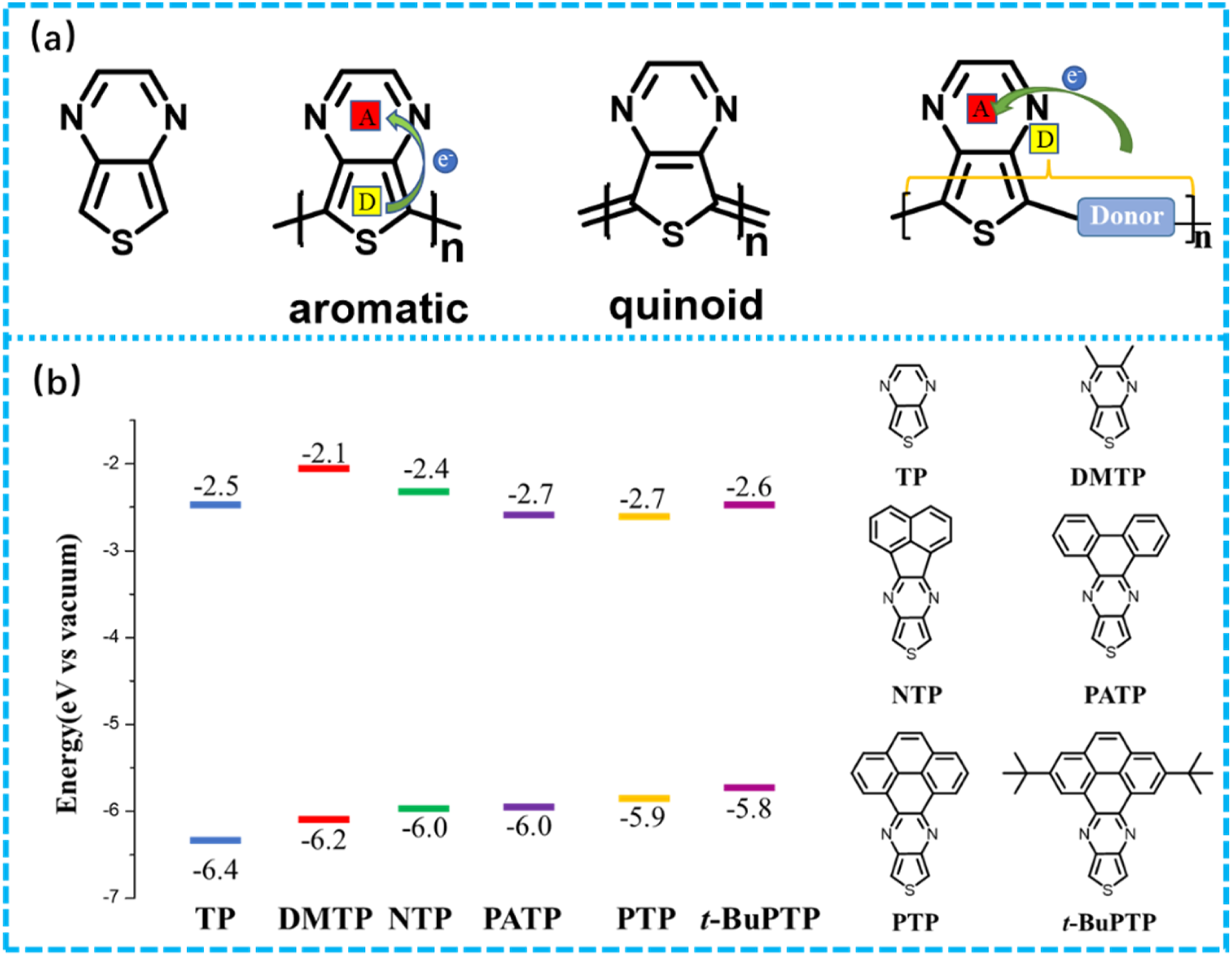
However, there are relatively few but remarkable studies and reports on electrode materials based on TP in the field of supercapacitors. As shown in Figure 8(b), McAllister et al. 108 designed and prepared multiple fused TP polymers as n-type electrode materials for organic supercapacitors. The results indicate that as bulk of the ring fused with TP enhanced, the band gap value of the obtained conjugated monomer structure would reduce. In a 0.1 M TBAPF6/acetonitrile electrolyte solution, the specific capacitance of the electrode ranges from 6 to 14 F/cm3 at a current density of 0.5 A/cm3 within potential range of −0.7 to −1.25 V.
Conclusion
In summary, the molecular design of high-performance conjugated polymers should be based on the concepts of molecular orbital energetics and crystal engineering, which require effective control of frontier molecular orbital energy levels and π orbital overlap in molecular design. As is well known, energy levels and bandgaps are mainly influenced by building blocks in conjugated polymer frameworks, and many conjugated framework molecules are designed and synthesized based on this theory.111–113 However, side chain engineering can not only serve as a traditional strategy for improving the solubility of conjugated polymers, but also significantly affect molecular stacking and π-π plane distance. 114 By utilizing side chain engineering and adjusting the branching points of alkyl side chains in conjugated polymers, the electrical properties of p-type,115–117 n-type,118,119 and bipolar conjugated polymers can be improved.89,120
The low energy density of supercapacitors is a key issue that restricts their development and application. According to formulas (6) and (8), increasing energy density requires consideration from two aspects: increasing the specific capacitance value and increasing the working voltage. Improving the specific capacitance value of electrode materials can be achieved by optimizing their chemical structure, morphology, and improving conductivity. Conjugated conductive polymers have high theoretical specific capacity, as well as a series of advantages such as easy preparation, easy modification, diverse structures, low cost, light weight, high conductivity, and thermal stability, making them preferred candidates for preparing high-performance and high-capacity supercapacitor electrode materials. Although it has been reported that pure polymer electrode materials still have low specific capacitance and conductivity, and their cycle life cannot meet the needs of actual energy storage devices, it is an inevitable trend in the field of capacitors to composite them with carbon materials or high specific surface area materials. However, the complex, cumbersome, and time-consuming preparation steps of composite materials, as well as the demand for certain special equipment, limit the development of conductive polymer electrode materials, indicating the necessity of designing conjugated conductive polymers with high specific capacitance, long cycle life, and high energy density.
Polythiophene has become the focus of conjugated polymer semiconductor materials due to its excellent optoelectronic properties, but its low air stability limits its practical application. The design of donor acceptor (D-A) type conjugated polymers is an effective way to improve their air stability and photoelectric performance while maintaining the excellent performance of polythiophene conjugated polymers through chemical modification of their molecular structure. Moreover, the D-A type structure constructed based on strong electron withdrawing building blocks, such as thieno[3,4-b]pyrazine, quinoxaline, benzotriazole and so on, will provide us with reference for more fascinating electrochromic and capacitive testing results.
Footnotes
Acknowledgments
The authors would like to acknowledge the support from the project “Research, Development and Industrialization of Cardiac Implantable Electronic Device/Pacemaker” funded by National Key Research and Development Program of China (Grant No. 2023YFC2411900) and Shandong Provincial Natural Science Foundation (Grant No. ZR2023QE032).
Declaration of conflicting interests
The author(s) declared no potential conflicts of interest with respect to the research, authorship, and/or publication of this article.
Funding
The author(s) disclosed receipt of the following financial support for the research, authorship, and/or publication of this article: this work was supported by the National Key Research and Development Program of China; 2023YFC2411900, Shandong Provincial Natural Science Foundation; ZR2023QE032.