
Abstract
The use of composite materials is widely spread across the Aerospace sector. Scarf and step lap joints are amongst the most commonly used methods for flush joint repairs; they restore original stiffness and nearly original strength. Prior investigations conducted by the authors have shown that bonded and hybrid step lap joints have superior static strength capabilities than bolted joints. Hybrid step lap joints have shown the highest fatigue resistance than its bolted and bonded counterparts. This investigation aims at optimising the previous step lap joint design containing five steps with a 90 mm long overlap length in order to improve joint efficiency. Four new step lap joint configurations are considered based on a parametric study conducted using Abaqus; two of which contain seven steps and a 130 mm long overlap (bonded and hybrid) whilst the other two contain six steps and a 105 mm long overlap (bonded and hybrid) with a tapered outer step region. Experimental tests right through to numerical modelling using three-dimensional (3D) finite element (FE) models have been investigated. Adhesive non-linear material properties, fastener contacts and friction forces were all included in the 3D FE models. The Multicontinuum Theory (MCT) is used to simulate the progressive failure process and determine the stress states in the four configurations. Overall the FE models are able to accurately predict the bonded and hybrid joint strengths and highlights the importance of not only optimising the number of steps and their lengths but also the individual step heights. This is a parameter which has often been overlooked by fellow researchers. Experimental results showed that all four step lap joint configurations have significant improvement under static and fatigue load cases; the greatest improvement is seen in the two bonded step lap joint configurations. Overall the hybrid joint configuration consistently outperformed the bonded joint configurations. The presence of fasteners supress crack propagation, minimise peak peeling stresses at the ends of the overlap and increase the durability of the joint. This enables early crack detection which can assist composite joint repair certification.
Introduction
The increased use of fibre reinforced polymer matrix composites for commercial and military aircrafts has resulted in the need for new, safe and efficient repair techniques. The three common methods for patch repair applications are through mechanical fastening, adhesive bonding and the combination of the two, called ‘hybrid’ repairs. Mechanical fasteners such as pins, rivets and bolts have commonly been used in the aerospace industry for decades.1–4 The key problem that arises through the use of mechanical fasteners is the high stress concentrations around the fastener holes which are more severe in composite laminates compared to metal plates.5,6
Adhesively bonded joints are structurally more efficient than mechanically fastened joints as they perform better in distributing loads, eliminating a majority of the high stress concentration problems seen in bolted joints.7–11 They are strong in shear but weak in peel hence it is important to use these joints under shear driven applications. One underlying weakness associated with bonded joints is its process control during repair applications. Improper processes would result in a weak bond that is not generally possible to be detected by means of non-destructive inspection (NDI). The detrimental effect of some improper surface treatment may not even manifest in a significant reduction of the initial static strength of the bond but in an adverse impact on the durability of the adhesive bond at service temperature and moisture environment and/or under fatigue loading. The difficulty to detect weak bonds is a major obstacle for certification of bonded repairs on primary structures.
The combination of mechanical fastening and bonding has been employed to safeguard against defects within the adhesive layer which may cause premature or catastrophic failure.12,13 It is only after the bond has failed where the fasteners begin to carry the remaining load in the joint. It is this safety factor that has allowed the certification of these joints in some aircraft structures.
For thick joint repair, scarf and step lap joints exhibit the highest structural efficiency as the stress is more uniform along the adhesive bond line compared to a simple overlap joint and the predominant load path eccentricities are eliminated. 14 Scarf lap joints are structurally more efficient as stress concentrations at the ends of the overlap are minimised. Stepped lap joints on the other hand, have similar structural efficiency as a scarf joint when viewed from a strength and fatigue point of view.15,16 In addition to this, step lap joints can be manufactured relatively easily and hence have been widely applied and investigated.15,17–20
Previously, Blaricum et al. and Seneviratne et al.21,22 investigated the performance of step lap joints present in the F/A-18 wing root. Graphite/Epoxy laminates were bonded to Titanium 6Al-4V and assessed under their compressive strength. Likewise, Kim et al. 15 evaluated the fatigue performance of adhesively-bonded composite step lap joints. The number of steps, joint length and edge angle of the adherends were investigated. They concluded that increasing the number of steps and edge angle has the greatest effect in improving bond strength and fatigue performance.
When it comes to numerically modelling composite step lap joints, complications arise due to determining which damage model to use in order to reliably predict joint strength. Orifici et al. 23 reviewed a number of methodologies which incorporate failure of composites. Examples of two-dimensional and three-dimensional analysis of simply bolted composite joints using finite element analysis (FEA) is reported in Refs. 24–26 and 27–33 respectively.
Experimental and numerical work has recently been conducted by the authors of this paper in the field of double lap joint repair34,35 and step lap joint repair36,37 using thin and thick composite adherends respectively. Various parameters were changed such as the fastener array, clamping pressure, bond strength and initial defects. Under static test conditions, both thin and thick lap joints found there was no significant difference between a bonded and hybrid configuration. However, fatigue testing using a block loading regime revealed a 26% and an 86% increase in durability of a hybrid double lap joint and step lap joint over their equivalent bonded double lap joint and step lap joint configuration respectively. Detailed numerical analysis conducted using Abaqus CAE was also able to accurately predict joint strength and stiffness in nearly all joint configurations. A Strain Energy Release Rate (SERR) method was adopted to further understand the fatigue behaviour numerically, by placing artificial cracks along the length of the bondline overlaps. The results concluded the clamping pressure provided by the fasteners in a hybrid configuration is vital in supressing rapid crack growth by reducing the peak peeling stresses and adds residual strength to the joint. Importantly the results indicated for hybrid joints, weak bonding can be reliably detected long before fatigue failure. The damage initiation and progression in the various configurations were successfully monitored using non-destructive inspection (NDI) methods such as visual inspection, ultrasonic A-Scanning and thermography. Overall the superior durability of a hybrid configuration and the added residual strength which provides a failsafe mechanism shows great promise in assisting composite joint repair certification.
The authors’ research on step joint repair described previously aimed at providing a benchmark comparison between fastened, bonded and hybrid configurations, however little effort was made in regards to optimising bonded and hybrid step lap joints. This paper aims at addressing this important issue. The previously tested bonded and hybrid step lap joint designs 36 are now optimised to achieve greater durability and strength by changing the number of steps, step lengths and individual step heights using detailed three-dimensional parametric models. Additionally, experimental tests leveraging off the same manufacturing methods and curing conditions defined in Ref. 36 were utilised; with results verified using analytical predictions. Overall this research aims to provide an optimum composite repair design while meeting certification requirements. All of which provides vital information to the aerospace industry and one which has seen limited research.
Step lap joint design
The previous studies36,37 conducted by the authors tested bolted, bonded and hybrid step lap joints, Figure 1. The investigation found that the outer steps should be kept smaller than the inner steps and increasing the number of steps is more effective than increasing the step length. In addition to this information, the following parameters were kept fixed in order to minimise the number of possible geometric variables: • Specimens are 24 plies thick (5.5 mm) with layup of [(0/90)/(45/−45)/(45/−45)/(0/90)]6 • Bondline thickness of 0.30 mm (controlled by the adhesive scrim cloth and curing jig) • Specimens have five steps • Specimens are one inch wide • Fastened and hybrid specimens have bolts placed central of each step • Countersunk fasteners torqued to 8.0Nm Layout of hybrid specimen (Configuration 5SH) with dimensions in mm; bonded specimen (Configuration 5SB) has similar dimensions without fasteners; fasteners placed central of each step.

The experimental static test results found that a bonded and hybrid joint containing five steps with a uniform step height was able to achieve 46.8% and 52.0% load recovery respectively compared to an undamaged parent structure. The objective of this study is to now achieve a higher load recovery (joint efficiency) using the same parent material as before.
Material properties
Material properties of HexPly M18/1/G939 carbon fibre prepreg. 38


Where, E11, E22 and G12, G13 are the materials Young’s modulus and Shear Modulus in the 11, 22 and 12, 13 direction respectively; ν12 is the in-plane Poisson’s ratio, Xt is the tensile stress, γp is the plastic shear strain; GIC and GIIC are the mode I and II fracture toughness.
Parametric study - new step lap joint design
Two parametric studies are conducted using Abaqus CAE to optimise the previous step lap joint design containing five steps with a 90 mm long overlap. Three-dimensional models containing orthotropic material properties for the adherends and elastic-perfectly-plastic material data for the adhesive was used. Fastener surface contact and frictional forces are included in the models. In order to accurately simulate the material failure behaviour, the micromechanical analysis method called the Multicontinuum Theory (MCT) provided by Autodesk as a commercial plugin to Abaqus was utilised.21,22 Micromechanical analysis takes an additional step beyond the conventional laminate theory to separate the stress and strain in the matrix and fibre from a Representative Volume Element (RVE). MCT predicts failure at the fibre and matrix level by obtaining the volume averaged stress states in both the fibre and the matrix, equations (1) and (2).

Accounting for stress variations through every fibre at every material point is not desirable. Hence, by providing constituent average stress and strain fields, a more manageable information window on composite materials response to a load is achieved. Based on the classical laminate theory, the stresses in the composite and constituents are given by:


The failure theory follows similarly to Tsai-Wu
42
and Hashin’s failure criteria.
43
Five isotropic stress invariants [I] are used:


Note that Hashin recognised that composites may have different ultimate strengths in tension and compression and hence both fibre and matrix have tensile and compressive sub-forms.
Matrix failure is assumed to be influenced by all six of the matrix average stress components in a 3D analysis whilst a quadratic function is used to find the average stress of the fibre.21,22 A unique aspect of the MCT failure criteria is that an anisotropic failure theory is used for an isotropic matrix material. This is because if all the fibres in a unidirectional composite for example were removed, holes in the matrix material will be present. Hence macroscopic failure in the material will be fundamentally different in the longitudinal versus transverse direction resulting in a transversely isotropic failure envelope.
44
Based on all of these assumptions, the matrix failure criterion is expressed as a quadratic function of the matrix average stress components:
Similarly, the fibre constituent failure criteria is expressed as a quadratic function of the fibre average stress components:
Overall, this model has successfully been used to accurately simulate the failure of double lap joints 35 as well as step lap joints. 37 Specimen geometry and hole boundary ratios were set similarly to previously investigated double lap joint and step lap joint configurations.35,37 8 node linear brick elements (C3D8) were selected for the composite adherends followed by a mesh convergence study. Each ply was set to be one element in thickness with hexagonal structured mesh controls. An average element aspect ratio of 4.22 was selected for bonded and hybrid step lap joints with a minimum element size of 0.2 mm to a maximum element size of 1.0 mm. Due to using the Autodesk MCT plugin, Nlgeom was set to off as joint behaviour was looked at up to the point of failure where the largest deformation was less than 1.5 mm. A master-slave algorithm with small sliding was allowed between contacting surfaces and a friction coefficient of 0.145,46 was set where applicable. The adhesive and adherend layer in the bonded and hybrid joint specimens were tied together using node-to-node contact allowing for small deformations. Failure was defined to occur when either the adhesive or adherend reached its critical shear/peel stress limit.
The models were able to accurately capture the three-dimensional stress states, material behaviour, bolt clamping, friction, secondary bending effects, load distribution as well as contact interaction between surfaces. Hence this study adopts the same modelling principles, but now applies them to the new step lap joint designs which are expected to provide the same level of accuracy as before. The fibre and matrix degradation values were set at 0.01 and 0.35 respectively. 35 MCT was able to reliably predict damage initiation as well as progression in each of the numerical models. However, MCT uses volume averaged micro-stresses which results in difficulty in incorporating damage degradation due to localised peak stresses. 47 Additionally convergence issues arise after damage initiation, resulting in increased simulation run time. The maximum stress criterion for fibre failure was additionally used to check for element final failure in all joint configurations.
The parametric studies determined the effects of varying step heights, step lengths and the number of steps with the following parameters kept fixed. • Adherend is 24 plies thick with a ply stacking sequence of [(0/90)/(45/-45)/(45/-45)/(0/90)]6 • Adherend is one inch wide • A total of five countersunk bolts used as the fasteners in a hybrid joint configuration, ¼ inch in diameter
This enabled a closer comparison between the new step lap joint designs with the previous step lap joint design discussed in above. Only bonded step lap joints were modelled in this parametric study as previous findings conducted by the authors revealed under static test conditions, there is minimal difference between a bonded and hybrid joint configuration.34,36 Furthermore, the residual strength in a hybrid joint repair is determined by the fastener joint pattern. In this case, the fastener pattern is kept the same as the previous step lap joint design (single array of fasteners discussed in Section 2.0). This results in a similar load-displacement relationship for the numerically modelled bolted joint configurations with different step geometry, thus providing approximately the same residual strength. Further details are provided in Section 2.3.1.
Optimisation - flush step lap joint design
The number of plies per step placed in a step lap joint made up of 24 plies with a fixed [(0/90)/(45/−45)/(45/−45)/(0/90)]6 orientation.


Bonded step lap joint specimens (not to scale); (a) Configuration 5; (b) Configuration 7; (c) Configuration 9A; (d) Configuration 9B; (e) Configuration 11; refer to Table 3 for configuration description.
The main aim of this section is to now improve the joint strength using the same parent material, hence the number of plies and its orientation were kept fixed. Figure 3 shows the peak load carried by each of the configurations modelled with varying step lengths using Abaqus CAE. Note: in all step lap joint cases the outer steps were kept 25% shorter than all the inner steps. This prevents the outer steps from being overloaded, causing premature failure.5,48 Peak load carried by various bonded step lap joint configurations made from 24 plies of HexPly M18/1/G939.
From the results in Figure 3, Configuration 5 and 9A with five and nine steps respectively show very similar strength characteristics. In general, it is clearly seen that increasing the number of steps whilst maintaining the same overlap length is more beneficial for a bonded joint. However, hybrid joints will also be manufactured using the same step configuration. This poses limitations on the minimum step length as the fastener to edge distance needs to be considered.
From Table 3, Configuration 9A has four ply thick outer steps whilst all the inner steps are two plies thick. In Configuration 9B the first four outer steps are only two plies thick whilst the inner two steps are four plies thick. Results in Figure 3 show it is much more beneficial to have thin outer steps which reduce peak shear and normal stress values, thus increasing joint strength.
Configuration 11 containing 11 steps also produces one of the highest joint strengths. A disadvantage with selecting this type of configuration is when considering its hybrid counterpart; this will result in an overlap length greater than 210 mm. From a repair point of view, it is ideal to achieve good load recovery whilst still minimising the area required for repair. This ensures further damage is not caused to adjacent pristine regions during the repair procedure. As a result, a specimen with seven steps is selected. Only five countersunk fasteners are used in the seven step hybrid configuration as bolt pull through is likely occur for the two ply thin outer steps, Figure 4. Two major geometry configurations; (a) Configuration 7SB – Seven Step Bonded Lap Joint; (b) Configuration 7SH – Seven Step Hybrid Lap Joint; B1-B5 = Bolt 1 – Bolt 5; bolts placed central of each step.
Optimisation - overlap step lap joint design
In addition to the previous flush step lap joint design, the presence of a thin overlap layer at the edge of a bondline is also often used in applications where the joint does not have to be strictly flush. Previous studies36,37 have revealed that the outer butt joint regions present at the very ends of a bondline overlap in a step lap joint configuration result in early cracking. The work shown in Ref. 35 highlights that adhesive spew fillets play an important role in reducing peak stresses found at the ends of bondline overlaps (double lap joints). Hence this section focuses on modifying a step lap joint originally containing five steps (Figure 1) with an overlap step region shown in Figure 5. Overlap step lap joint optimisation; dimensions in mm and filler adherend placed on bottom right-hand end with a 0.3 mm thick bondline.
Each of the steps consists of four plies with the same orientation as the parent structure. In this case, dimensions defined in Figure 1 were kept fixed with all specimen being one inch wide. Once again a three-dimensional parametric study is conducted similar to Section 2.2.1 with the aim of optimising the ‘overlap length’ to improve the peak load carrying capability of the joint.
From the results shown in Figure 6, an outer overlap length of 15 mm provides the highest failure load for the bonded step lap joint. This results in a total bondline overlap length of 105 mm. The preliminary FEA results predict a peak load of 41 kN achieved by this bonded overlap configuration. The hybrid specimen in this case, consists of five countersunk fasteners placed central of each step aft of the initial overlap length. Due to the increase in thickness caused by the overlap, a filler adherend on the bottom right-hand end of Figure 5 is used to maintain a bottom flush region. This will increase the joint stiffness and reduce the out of plane bending. Optimising overlap length to improve the peak load carried by a bonded overlap step lap joint specimen.
Based on all of these results a total of four new configurations have been selected for static and fatigue testing, Figures 4 and 7: Two major geometry configurations; (a) Configuration 6SB – Six Step Bonded Overlap Lap Joint; (b) Configuration 6SH – Six Step Hybrid Overlap Lap Joint; B1-B5 = Bolt 1 – Bolt 5; bolts placed central of each step.

Computational results
The following sections numerically compare the new step lap joint designs (Configuration 6S and 7S) with the previous bolted, bonded and hybrid step lap joint designs containing five steps. Model setup is the same as Section 2.0. Specimens containing an adhesive layer had four elements placed through its thickness whilst a longitudinal displacement in the (1) direction defined in Figures 4 and 7 is placed on the right-hand end of each specimen. Displacement in the (3) direction is constrained on the right-hand end and a clamped boundary condition is applied on the left-hand end.
Fastened step lap joint
The fastener array in the new step lap joint designs as well as the previous step lap joint design is the same. A total of five countersunk bolts is used in each of the fastened configurations similar to Figures 1, 4 and 7. The three fastened step lap joints considered are:
Figure 8 shows the load-displacement relationship for the three fastened configurations. Overall there is no significant difference between the configurations due to the similar fastener array. The highest joint stiffness is achieved by Configuration 6SH due to the larger joint thickness. Configuration 5SF and 7SF have a very similar joint stiffness as they share the same joint thickness. However, a marginally higher joint stiffness is seen in Configuration 7SF due to the larger overlap length; this results in greater friction between the adherends. The results overall show that the residual strength provided by the fasteners in the new hybrid configurations is slightly higher than that in the old configuration, Figure 8. Load-displacement comparison of numerically modelled fastened step lap joint configurations for residual strength comparison.
Bonded step lap joint
A comparison is made between the three bonded step lap joint configurations in Figure 9. The previously tested flush bonded step lap joint with five steps (Configuration 5SB) has the lowest peak load failing after 34.13 kN based on the numerical results. The bonded overlap step lap joint specimen containing six steps (Configuration 6SB) has the greatest joint stiffness. Once again this is due to the increased thickness where a peak load of 40.85 kN is achieved. This provides a 20% increase in failure load. The highest joint load was carried by the flush bonded step lap joint with seven steps. A peak load of 43.99 kN is predicted from the detailed numerical model. This results in a 29% increase in failure load. Load-displacement comparison of numerically modelled bonded step lap joint configurations.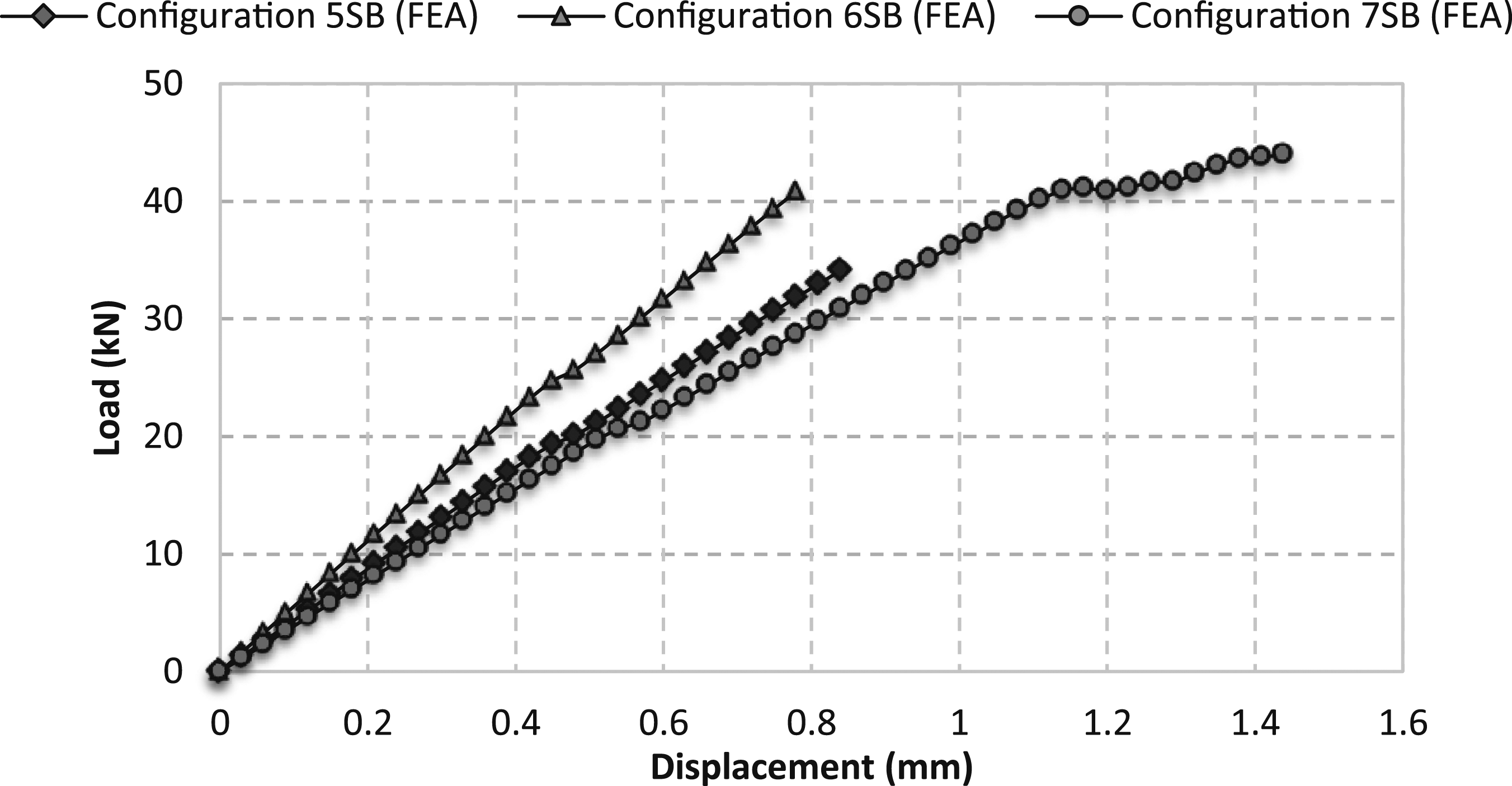
Overall, the new optimised step lap joint containing either six or seven steps have shown improvement over the step lap joint design containing five steps. Based on these results, the shear and normal stress distribution for Configuration 5SB, 6SB and 7SB are shown in Figure 10. All three stress distributions show peak stresses occurring at the start and end of each step. Configuration 5SB reached its peak failure load of 34.13 kN with a remote strain of 6054µƐ; peak stresses occurred at the very ends of the overlap. Configuration 6SB containing an outer overlap, in fact, reduced peak stresses found at the outer butt joint region due to the tapered adherend. A peak load of 40.85 kN was predicted by the numerical models in this case based on the maximum stress criterion. Peak normal and shear stress values occur at the very end of the overlap where the butt joint regions are present, i.e. adjacent to the filler adherend. This is the location in which failure originates from. Finally, Configuration 7SB failing at a peak load of 43.99 kN has the maximum elongation of 1.44 mm reaching a remote strain of 7440µƐ. Based on the new bonded step lap joint designs, experimental tests are conducted to verify the results. Comparisons between the two are made in Section 3.2. Comparison of adhesive stress distribution midway through the width of the specimens; (a) Configuration 5SB; (b) Configuration 6SB; (c) Configuration 7SB; (σ33–Normal Stress, σ13–Shear Stress).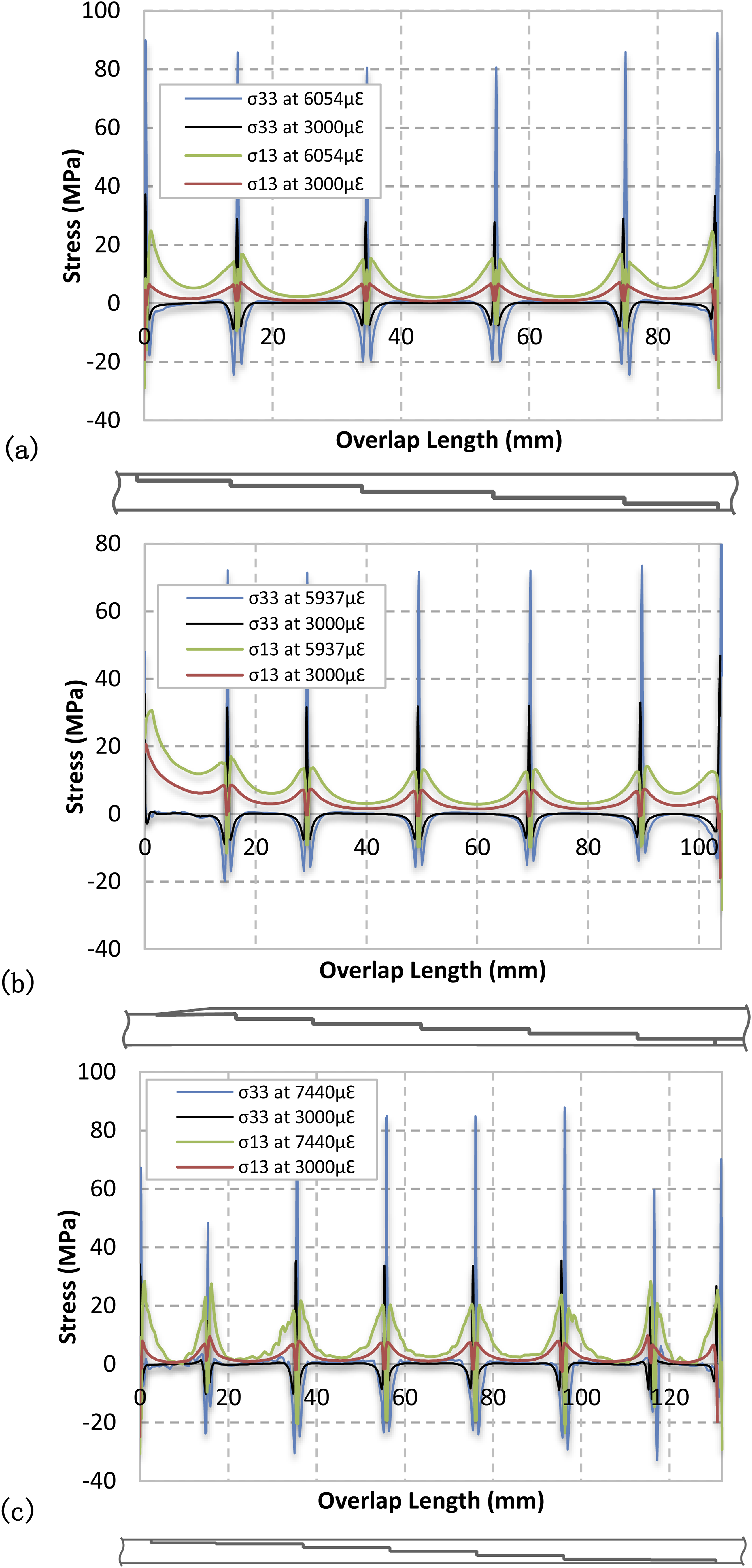
Hybrid step lap joint
The numerical load-displacement curves for the hybrid step lap joint configuration are presented in Figure 11. Once again peak stresses occur at the start and end of each step. Figure 12(a) shows the highest stress reached at the butt joint region located closest to the end of the overlap (closest to bolt 5). This step lap joint containing five steps has the lowest peak load of 34.99 kN with a 1.02 mm long displacement. Comparing the two new step lap joint configurations, only a 4% difference in peak load occurs. Configuration 6SH is predicted to reach the highest peak load of 38.69 kN. Load-displacement comparison of numerically modelled hybrid step lap joint configurations. Comparison of adhesive stress distribution midway through the width of the specimens; (a) Configuration 5SH; (b) Configuration 6SH; (c) Configuration 7SH; (σ33–Normal Stress, σ13–Shear Stress).

Figure 12(b) and (c) shows the stress distribution in each of the new step lap joint configurations. The stress distribution follows similarly to the equivalent bonded step lap joints discussed in Section 2.3.2. The presence of five fasteners in each of these configuration does significantly reduce the peak normal stresses (σ33) present at the start and end of each step thus highlighting the significance of fastener clamping.
Figure 13 shows the bolt load share comparison (load carried by the fastener/joint load) between the two new hybrid configurations. Fasteners have the highest contribution in Configuration 7SH but only carry 3.52% of the total load before final failure occurs. Configuration 6SH reaches a peak load share of 2.55% before final failure. Due to the higher remote strain in Configuration 7SH, a greater portion of the load is distributed amongst these fasteners. Overall it is clearly seen that increasing the applied load results in greater load share in hybrid configurations but the overall contribution is minimal compared to the bonded portion of the joint. The fact that specimens with a higher strain (greater overall elongation) result in increasing bolt load share - agrees with prior findings reported by Kelly et al.
49
which states fasteners play a greater role in the load share of a joint when the modulus of the adhesive is reduced. Comparison between experimental and numerical load-displacement results are provided in the following sections. Bolt load share comparison between Configuration 6SH and Configuration 7SH; Failure Load - the peak load carried by the configuration before final failure; Applied Load - total load carried by the configuration for a given point in time.
Experimental validation
Based on the numerical result previously discussed, it has been demonstrated that the two new step lap joint designs (Configuration 6S and 7S) are predicted to have greater joint strength than the previous step lap joint containing five steps. In addition, the three fastened step lap joints provide approximately the same residual strength and are in fact weaker than their equivalent bonded and hybrid configuration. From a certification point of view, bonded and hybrid joint repairs are not widely seen in aircraft structures. Hence an experimental test plan is conducted to static test the individual bonded and hybrid joint strengths and then compare them with their numerical models. Fatigue tests are also conducted based on the same block loading regime implemented in prior tests conducted by the authors’.34,36
Specimen manufacture and methodology
Based on the numerical results discussed in Section 2.0, a 24 ply thick panel made from HexPly M18/1/G939 carbon fibre prepreg was cured in an autoclave. This is the same material previously used to test the step lap joints containing five steps. 36 Specimens were machined to size using an NC machine followed by machining the individual steps. The surfaces were then prepped for bonding. This involves abrading the adherends with ScotchBrite 7447 followed by degreasing using Methyl Ethyl Ketone (MEK) then blasted with 50 micron diameter aluminium oxide grit propelled with high purity nitrogen gas which is also used to remove excess grit. Specimens containing fasteners had holes machined after the bondline was cured. This removes complexities involved in accounting for bondline offsets between adherends and countersunk depths for the thinner steps whilst also allowing for the installation and removal of fasteners at any time.
After specimen assembly, static and fatigue tests were conducted on an INSTRON 1342 machine with a 100 kN load cell controlled by a computer running MTS software. Static tests were conducted on all four specimen configurations at a rate of 1 mm/min with axial load and displacement measurements recorded until catastrophic failure. Fatigue tests were conducted based on a block loading regime at a frequency of 5 Hz and a stress ratio (R = σmin/σmax) of 0.1.
Static test results
Experimental load-displacement data for the two new bonded and two new hybrid step lap joint configurations are now compared to the numerical results discussed in Section 2.3. Figure 14 shows the comparison. The predicted peak failure load matches closely to the average experimental test data. Table 4 summarises the peak static force data for the four specimen configurations. Comparison of static load-displacement results for four specimen configurations tested experimentally and verified through FEA Peak static load achieved by four specimen configurations loaded at a rate of 1 mm/min.

The trend also shows that an overlap step lap joint with six steps has a greater stiffness than a specimen with seven steps. In addition, hybrid step lap joints have lower joint stiffness than their bonded joint counterpart due to the reduced bond area. Figure 15 shows the failure location for the four different specimen configurations. As previously discussed, the MCT failure criterion was utilised to impose the progressive damage parameters to the fibre and matrix whilst the maximum stress criterion (max stress component in the loading direction) was used to determine the point of failure on the load-displacement curves. Predicted failures modelled numerically; (a) Configuration 6SB; (b) Configuration 6SH; (c) Configuration 7SB; (d) Configuration 7SH; blue - undamaged laminate, green - matrix failure, red - fibre failure.
The numerical results in this case provided conservative estimates for failure load with the exception of Configuration 6SB which over predicted failure load by 4.5% (40.85 kN). Both numerical and experimental data highlighted that Configuration 7SB reaches the highest peak load limit of 49.06 kN. This configuration was almost able to achieve a 70% load recovery compared to a pristine undamaged parent structure which is an 18% increase over the previous step lap joint design containing five steps in a hybrid setup (Configuration 5SH). This thereby highlights that it is not only beneficial to increase the number of steps in these thick joint repairs but also important to minimise the outer step heights to reduce peak peeling stresses present at the outer ends of the overlap.
Overall across the four specimen configurations experimentally and numerically tested, a high degree of accuracy is seen using the MCT progressive damage model. By using orthotropic material properties for the adherends, elastic-perfectly-plastic material data for the adhesive and by carefully modelling the contacts and frictional behaviour, reliable joint predictions are possible using numerical models. This will definitely serve as a vital tool in predicting the repair strength of composite adherends and aid the certification of new repairs.
Fatigue test results
Block loading regime – strain amplitude increased every 105 cycles; frequency = 5 Hz, r-ratio = 0.1.

Fatigue resistance of four specimen configurations under block loading; r-ratio = 0.1; frequency = 5 Hz.

Configuration 6SB and 6SH also produced a higher fatigue resistance compared to the original bonded and hybrid step lap joint configuration containing five steps (Configuration 5SB and 5SH). Configuration 6SB produced a 23.8% improvement in fatigue resistance whilst Configuration 6SH produced a 32.0% improvement. Overall although a significant increase in fatigue resistance is seen in the new bonded step lap joint configurations, the hybrid step lap joints still have superior fatigue durability over their bonded step lap joint counterparts. This highlights the importance of clamping pressure provided by the fasteners which supress rapid crack growth and add residual strength to the joint repair which is vital for certification.
Discussion
Experimental results have shown that Configuration 6SB and 6SH produce very similar static strength characteristics. Based on the experimental results, the bonded joint Configuration 7SB catastrophically fails after 49.06 kN which is 20.1% higher than its hybrid joint counterpart; Configuration 7SH. This result suggests it may be possible to achieve suitable joint performance from a bonded joint which is comparable to a hybrid joint. However, the presence of initial bondline defects will reduce joint efficiency whilst hybrid joints offer the added residual strength. Overall under static test conditions, a specimen with seven steps containing thin outer steps and thicker inner steps is more efficient in a bonded setup. However, under fatigue cases, hybrid configurations are still more beneficial due to the added clamping pressure from the fasteners which improve fatigue performance.
Failure of four step lap joint configurations fatigue tested using a block loading regime; r-ratio = 0.1.


From Configuration 7SB in Table 7 and Figure 15(c), failure does not occur at the ends of the bondline overlap; instead, failure occurs at the start of the four ply thick steps. This is the location of peak normal stresses resulting in fibre pull-out and net tension failure. For Configuration 7SH the adherend fails at the end of the second step (left-hand side). It must also be noted that further improvements may be possible if the ply orientation was not kept fixed.
Overall the results discussed here clearly demonstrate that joint strength and durability for both bonded and hybrid step lap joints can be significantly improved by optimising the individual step heights let alone varying the number of steps and step lengths. In addition to this information, if a flush repair is not required, a simple overlap step can be employed to reduce peak peeling stresses present at the ends of the bondline overlap. This has the advantage of minimising the repair area whilst still achieving high strength and resistance to failure. Through the series of parametric models conducted using Abaqus CAE, four new step lap joint design were analysed and tested. The new bonded Configuration 7SB achieved the highest peak load of 49.06 kN which increased the load recovery to nearly 70% for step lap joint repair as opposed to 52% for the previous hybrid step lap joint with five steps. The hybrid configurations did, however, achieve the greatest durability with Configuration 6SH failing after 527,976 cycles which is a 32% increase in fatigue resistance than Configuration 5SH.
Conclusion
Through the parametric study conducted in Abaqus, four new step lap joint configurations were experimentally and numerically tested. The aim is to achieve higher joint strength and fatigue durability compared to a baseline design of bonded and hybrid step lap joints containing five steps. The parametric study confirmed that increasing the number of steps in a joint is more beneficial than increasing step length. Furthermore, optimising the ply orientation for each joint configuration will result in better joint efficiency. The study shows that by varying the individual step heights, similar if not better joint efficiency can be achieved than a joint with more steps and a constant step height. This presents the advantage of minimising the joint region particularly in repair cases by ensuring further damage is not caused to adjacent pristine regions during the repair procedure. The numerical work conducted using the micromechanical MCT progressive failure model and non-linear adhesive properties showed a good comparison between FEA with experimental results. The highest peak load of 49.06 kN was achieved by the bonded joint configuration containing seven steps with a 130 mm long overlap. This improved the joint efficiency close to 70% compared to a maximum joint efficiency of 52% achieved by the previous step lap joints containing five steps.
The overlap step lap joint specimens (Configuration 6SB and 6SH) containing a 105 mm long overlap were also produced with the aim of minimising early crack initiation commonly originating from the outer butt joint regions. Experimental results found that the hybrid joint Configuration 6SH produced the highest fatigue performance of 527,976 cycles based on the block loading regime used. The hybrid joint Configuration 7SH with seven steps failed after 475,309 cycles. All four configurations tested achieved better static and fatigue performance than the baseline bonded and hybrid specimen containing five steps. Under static test cases the bonded Configuration 7SB reached a peak load 25.5% higher than Configuration 7SH, however under fatigue - hybrid joints have superior durability. Hence the relative static strength characteristics of a joint should not be used as an estimate for joint fatigue life. Overall the clamping pressure provided by the countersunk bolts aid in delaying sudden crack propagation and minimise peak peeling stresses typically found in bonded joints. This aids in significantly increasing joint performance and durability and may assist in hybrid joint certification for aircraft structures.
Footnotes
Acknowledgments
This work was undertaken as part of a CRC-ACS research program, established and supported under the Australian Government’s Cooperative Research Centres Program. Special thanks to Ivan Stoyanovski for his help and advice during the specimen manufacturing stage.
Declaration of conflicting interests
The author(s) declared no potential conflicts of interest with respect to the research, authorship, and/or publication of this article.
Funding
The author(s) received no financial support for the research, authorship, and/or publication of this article.