
Abstract
This paper focuses on the latest development of a solid hexahedron element for composite delamination analysis. The 8-node solid is derived from a 20-node hexahedron. It is transformed into two physical independent 4-node shell elements according to the propagation of delamination process within the element. This transformation is driven by a transfer and damage laws that are defined by calibrating the element with a FE modeling for a double cantilever beam (DCB) test. According to the position of the crack in the element, one parameter defines the degradation of the transverse properties at the Gauss point as well as the transfer of the volume element towards the bi-plate formulation. A sensitivity study of the element is presented. A global-local finite element approach coupled with the traditional virtual crack closure technique (VCCT) method allows to calculate the energy release rates and to control the propagation of cracking in the element. This method is validated by comparison between conventional FE models and experimental tests [DCB, and end load split (ELS)]. Experimental asymmetric double cantilever beam (ADCB) test is carried out and modelled using the developed element. The numerical simulation properly correlates with the experimental results.
Introduction
Delamination of laminated composite structure has been the subject of intensive research for many years from both an experimental and a numerical standpoint. This failure mode is particularly very difficult to detect. Numerically, two approaches are used in the literature to model the delamination, the first approach is based on damage mechanics and the other one is based on fracture mechanics. This damage mechanics approach was first applied to the analysis of concrete cracking [1]. It consists in introducing interfacial elements between composite layers. The behaviour of the interface elements is controlled by relationship between the gap opening and the traction across the interface. A great number of authors have developed different relationships such as simple bilinear, exponential or linear exponential [2–8]. The area of the stress-relative displacement curve equals the critical energy release rate. This method can provide an energy dissipation mechanism due to the development of micro-cracks and micro-voids within the composite. However, cohesive elements require a fine mesh which can become prohibitively inaccurate in industrial application when a larger mesh size is used like helicopter blades or sine-wave crash absorber beams.
Turon & al. developed in [9] two new guidelines to adapt the cohesive elements in the use of coarse meshes. It offers a mechanical approach to determine the interface stiffness sufficient to limit the oscillations. By adjusting the maximum interfacial strength, the results on the modeling of a DCB test with cohesive elements are correct. Although for accurate simulations a minimum number of elements are necessary within the cohesive zone.
The fracture mechanics approach is based on the computation of the energy release rate that is compared to the critical value. Energy release rates are usually evaluated using the virtual crack closure technique [10–13]. The VCCT technique is based on Irwin's assumption that when a crack extends by a small amount, the energy released in the process is equal to the work required to close the crack down to its original length. It is one of the most efficient and robust tools to compute energy release rates within one step. However, the use of VCCT to simulate delamination growth requires complex moving mesh techniques to advance the crack front. An automatic adaptive remeshing or a relatively fine mesh in the crack tip area is thus required. A pertinent analysis of the behaviour of a DCB test and results on the modeling with different methods is presented in [14].
A new approach for composite delamination analysis in mode I is presented in [15]. It is based on the use of a multi-layered 8-node solid element with 48 degrees of freedom. This element represents delamination by converting it into two separate 4-node shell elements. Thus, the decrease of the local moment of inertia and consequently the decrease of the bending stiffness and buckling resistance are correctly represented. The delamination criterion is based on the evaluation of the energy release rate according to the classical beam theory. Double Cantilever Beam testing is used to correlate this approach. The numerical simulation matches perfectly the experimental results.
For industrial structures need, this technique of delamination modeling may be very interesting. This multi-layer approach allows having only one element through the laminate thickness and can reduce consequently the total number of elements of FE models. However this technique remains limited to model only the delamination in mode I.
In this paper, we will present another new approach regarding the delamination control. This approach is based on a global-local formulation. This makes it possible starting from an initial FE calculation to determine the energy release rates. The control of delamination is based on the traditional VCCT method. The advantage of this approach is that it deals with delamination modeling in mode I, II and combined mode (I + II).
The Multi-Layered Element Formulation
The 8-node solid element with 48 degrees of freedom was originally introduced by Yunus & al. [16]. It is derived from a 20-node hexahedron element with 60 degrees of freedom. In addition to the three translational degrees of freedom, the 8-node element has three rotational degrees of freedom which allows a feasible connection to shell elements.
The element, as introduced by Yunus & al., has a Poisson's ratio locking that is characterized by an excessive bending stiffness [17]. This was corrected in reference [18] by modifying the element formulation and allowing quadratic displacement along the edge that depends on nodal rotations. The solid element can be converted into two physically independent shells of Belytschko-Lin-Tsay type [19]. The shell elements represent the laminate plates after delamination. The upper shell is made up of the upper four nodes of the element, while the lower shell is made up of the lowers four nodes. The change from a volume to a bi-plate configuration is done without modifying the mesh, which features an interesting outcome for the computation time.
However, the instantaneous release of nodes can give rise to undesired severe oscillations. This might occur in delamination models when the distance of the crack progression is done by allowing elements on opposite sides of the crack to debond. Therefore, the debonding is done gradually by defining a hybrid formulation of the element.
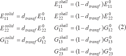
So the developed element can exist in three different states: first, as a classical solid element in the case of no delamination (Fig. 1.a); second, as a hybrid state where delamination is being spread in the element (Fig. 1.b) and finally as double-shell state where the delamination has completely crossed the element (Fig. 1.c). When the delamination is located within the element, the hybrid state is composed of a superposition of a solid element and two shell elements. The element is defined according to a preferential plane (plane 12), the same as for a classical composite volume element. The crack will supposedly spread through this plane, perpendicularly to the face of an element. According to the crack location within the element, this approach consists in transferring the plane stiffness (E11, E22, G12) from the volume into the plates, and then, damaging the transverse properties (E33, G13, G23).

Models considered to compute damage law
Many studies have been conducted to describe the phenomena involved locally. The phenomenon of delamination is controlled by the cracking and splitting of the matrix. It depends on material's system, stacking sequence and also on the fiber orientation of the neighboring plies of the delamination [20–21]. In our study, the approach is made with a higher scale. The damage of the transverse properties of the element represents the delamination of the laminate across the element, and represents also all the local behavior in general way. It then allows a good representing of these phenomena for structures in industrial scale. Three damage parameters (di, i = 1-3) control the damage laws by multiplying the transverse properties depending on the crack location in the element (Fig. 2). The damage is achieved independently for the 3 distinct zones defined by the position of Gauss points in the element. Nine integration points per ply have been used, i.e., 3 per face

Models considered to compute damage law, (a): FE Model, (b) 1D hybrid formulation
(dtransf) is a transfer parameter that allows a gradual decrease of the in-plane properties of the solid element (E11, E22, G12) and a gradual increase of the shell material properties simultaneously. The resulting in-plane stiffness (E011, E022, G012) remains unchanged.
(dtransf) and (di) are functions of the crack length which is considered as known: they are equals 1 when there is no delamination and 0 when the crack length is equal to the element length. The modulus of an element containing the crack can be written as:
Transverse stiffness damaging:

In-plane stiffness transfer:
The hybrid formulation of the element models the part of the structure containing the crack front. Its rigidity is determined from the transfer and degradation functions. These laws are established by calibrating the behavior of the element in modeling a FE DCB test. As the crack is assumed to propagate perpendicular to the face of an element, this calculation can be represented by a 2D equivalent FE modeling. Two types of modeling have been made.
The first consists of a 2D finely meshed model with an initial crack (Fig. 2.a). The structure is loaded in mode I by a unitary load. The values of the displacement of node (A), ut and wt along the x and z axes respectively and rotation θt relative to the y axis, are calculated for different values of crack length.
The second one (Fig. 2.b) is an identical to the first modeling but is made with the developed element. In 2D, the hybrid formulation of the element is equivalent to two 1D beam elements and a shell element representing respectively the two plates and the volume of the 3D formulation. This 2D approach simplifies the calculation of transfer and degradation laws.
The displacements and rotations at the node (A′) of the element, u't, w't & θ't, are defined by the stiffness matrix which is written based on the following unknowns:

Where Ebeam is the beam Young modulus, E11 and E33 are the in-plane and the transverse Young modulus, G13 is the shear modulus and di are the damage parameters.
For a given crack length (a), the value of parameters (di) are obtained by minimizing the equation (4):

The minimization and the resolution of equations (3) and (4) for different crack lengths allows to plot the variation of the damage and transfer parameters, di and dtransf, as a function of the crack length (a) inside the element. The damage and transfer laws obtained are shown in (Fig. 3.a and 3.b). These laws govern the transformation from the solid state to the double-shell state. They affect the response evolution of the model from the moment when the crack reaches an element until the moment when it passes through.

Damage and Transfer laws as a function of crack length, (a) Damage laws, (b) Transfert laws
As shown in the (Figs. 4.a, 4.c, and 4.d), the material characteristics E11, G13 and v13 have very little influence on the displacement of point wt(A). Only the E33 module, that represents the transverse stiffness of the laminate due to the behavior of the resin, affects directly the displacement (Fig. 4.b). As we can see, the variation of displacement is high for low values of E33, although then it stabilizes when the value varies between 4000 and 10000 MPa that is the range of variation usually obtained for such materials. Even if the parameters (di, i = 1-3) and (dtransf) can not be regarded as generic, their variation is not very sensitive to different characteristics of the laminate.

Influence of material's characteristic on the tip displacement
To validate the behavior of the hybrid formulation, three models of DCB, ELS and ADCB tests are performed: a conventional model FE performed with a refined mesh (1 element per ply) and another model created from the developed formulation (Fig. 5). Three parameters were evaluated: the size of the hybrid element, the length of cracking, and transversal position of the crack in the element. For this, the relative difference of displacement obtained from the two types of models by applying the same load, is identified.

Validation of transfer and damage functions, a) DCB validation, b) ELS validation, c) ADCB validation
Fig. 5 shows the results for the models of DCB (Fig. 5.a) and ELS (Fig. 5.b), for 3 element lengths (L, 2.L and 4.L), for 2 thicknesses element (L and L / 2), and for 3 crack length (25%, 50%, and 75% of L). For ADCB models (Fig. 5.c), 3 other parameters were tested, in changing the position of cracks in the thickness of the element (25%, 50%, and 75% of e). For all these parameters tested, the relative difference between the 2 models when we apply the same load is less than 5%. The behavior of the element in the hybrid formulation is correct even with a plan of cracking different from the mid-plan of the element. All these results validate the calculation of transfer and damage functions.
These functions represent correctly the behavior of the structure in the presence of a crack. This type of approach can be improved by performing the calibration procedure upstream of the full. This procedure, which is based on linear calculations, is simple and quick to implement. This can ensure a better behavior of the developed element. Its behavior is very acceptable in the range of variation that has been validated.
Generally speaking, the approach presented in this study is taken from the VCCT method which consists in computing the energy release rate in terms of forces and displacements located at the crack front. Moreover, our modeling is based on the use of a single element in the thickness of the laminate. The forces and displacements computed at the nodes of the element featuring the crack are too far away from the crack front. Thus the computation of the energy release rate will not be accurate. In order to control the crack propagation, a global-local approach is proposed. It is based on a FE computation with a refined model of the laminate part which contains the crack front. This computation is carried out once, ahead of the modeling process and it then allows piloting the computations of the energy release rate in the element.
The meshing is conducted with one element per ply (Fig. 6). To avoid problems linked to the local approach of the model, the ends of the mesh are stiffened by a rigid body. Its length is at least three times the length of the hybrid element used. The boundary conditions imposed on the model are isostatic. They don't introduce any parasitic load into the computation.

local FE model
For each of the four nodes (Ni), three calculations are made: two unitary loads (Fx(Ni), Fy(Ni)), and one unitary momentum (Mz(Ni)) are applied successively. For each computation, the internal load and the displacement in front of the crack were considered. The value of Fx and Fy are evaluated with a rigid body that connects two superimposed nodes of the crack front. To calculate the opening, the horizontal (ut, ub) and vertical (vt, vb) displacements of the first two nodes located before the crack front are noted. These twelve computations are used to define relationships between the loads and moments applied to the nodes (Ni) and the loads and the opening in front of the crack.
For a given length of crack (d) and by applying the principle of superposition, these relationships are written in the form of a matrix
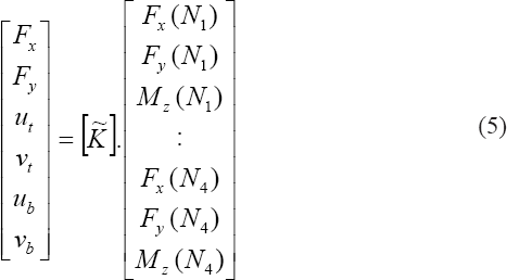
Where
These relations are independent from the global stiffness of the structure. It is important to notice that this calculation which is made once at the beginning of the calculation process is a very fast linear calculation to conduct. It makes possible to perfectly determine the stress distribution, whatever the stratification and the size of the elements.
The energy release rates are calculated at the local level in mode I and II by applying the VCCT technique:
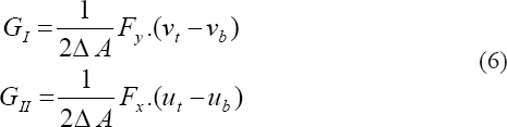
Where: ΔA is the delaminated surface.
At the level of the global model, and for an element containing the crack with a delaminated surface ΔA, it is possible to determine the values of GI and GII depending on the forces and moments calculated at the element's nodes with the relationships (5) and (6).
To use equation (5), loads and moments determined on the nodes of the hybrid element are recalculated for the nodes (Ni) defined on the local model. This transportation distance depends on the element length and on the position of the crack in the element. Equations (5) and (6) then make it possible to determine the loads and the opening in the crack front and the energy release rates.
The criterion used for the modeling of the propagation of delamination is as follows:
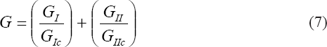
Where GIc and GIIc are respectively the critical energy release for mode I and mode II.
This linear criterion is established in terms of an interaction between the strain energy release rates (GI/GIC) and (GII/GIIC), and the use of three fitting parameters, to describe the fracture critical surface. It's widely used and represents the data with reasonable accuracy.
If G ≥ 1, the delamination within the element increases by (ȧ × Δt) where (Δt) is the time step and (ȧ) the propagation velocity of the crack. Theoretically (ȧ) depends upon the sound speed in the material and upon the energy stored in the structure, that is to say:

where C is the propagation velocity of the sound in the material, and ω is a damping coefficient.
To validate the calculation of the rate of energy release in the hybrid element, a FE study is performed. The model consists of 46 carbon plies (T300/914). The material characteristics are E11 = 130000 MPa, E22 = 11000 MPa, G12 = 5500 ν12 = 0.35, and the stacking sequence is [(02/90)7/02 // 02/(02/90)7]. The dimensions of the model in mm are 100 × 20 × 5.98. The crack length varies between 55mm and 59 mm. The structure is clamped on the opposite side of the crack, displacement is imposed at the other end
The reference model consists of 10580 quadratic elements (230 elements in length, and 1 element per ply). The mesh of the area in which the calculation of energy release rate is made is refined; the size of elements is reduced to 0.125mm x 0.13mm.
The model is realized with 20 elements of 5mm length. 11 elements are completely cracked, they represent the two plates. Then, one element is in the hybrid state that contains the crack. Finally, 8 elements are in volume state (without damage).
The graphs in (Fig. 7) represent the calculation of G (energy release rate) for a propagation of the crack for 14-mm which impact 3 consecutive elements, and for 2 types of loading: DCB (Fig. 7.a) and ELS (Fig. 7.b). The values of G calculated from the 2 models are very similar. The maximum error observed is less than 5%. These results validate the local-global approach developed.

Validation of G calculations, a) G - DCB test, b) G - ELS test
In order to validate the modeling principle for mode I, II, and combined, experimental ADCB test is carried out with a pre-impregnated carbon woven fabric (G803/914). The stacking sequence consists of 16 plies with the same orientation. The initial crack length is 55 mm. Its position is located at ¼ of the thickness. The characteristics of the specimens are presented in Table 1. The experimental tests were conducted using a tensile testing machine allowing the acquisition of vertical displacement and the applied load. The boundaries conditions are free. The loading is carried out by imposing a vertical displacement. This displacement is carried out stage by stage. After each loading stage or as soon as the crack is propagated, the imposed displacement is stopped. Then the length of the crack and the maximum load reached, as well as the stabilized final load after the crack propagation are recorded. Several specimens are tested.
Characteristics of ADCB specimen

Characteristics of ADCB specimen
To validate the element and the approach developed in this study, the experimental test ADCB is modeled. As shown in (Fig. 8), the mesh is composed of 56 elements, including 45 solid elements and 11 hybrid ones. The material characteristics are shown in (Table 1). The values of the critical energy release rates obtained from experiments are GIC=0.55N/mm and GIIC=0.7N/mm

(a) Initial ADCB FE model: 18 solid elements, 2×14 shell elements, (b) Comparison between experiment and simulation, (c) Crack growth inside the ADCB
To model the ADCB test, the loading is applied by imposing a vertical displacement per stage of 1 mm opening. The displacement is imposed on the nodes which correspond to experimental test. (Fig. 8.b) presents the curves load/displacement obtained numerically and from experiments. The behaviour of the numerical model corresponds to that observed in experiments. The propagation of delamination calculated by the numerical model is rather close to that measured in experiments (Fig. 8.c). The damage and transfer laws representing the crack propagation inside the element seem to correspond well to the real delamination propagation inside the structure. This new approach based on a relatively low number of elements, allows to correctly representing a composite structure delamination. It can be used for complex models without the need for a high number of elements.
Crack propagation inside the element is well represented by a damage law that affects the transverse mechanical properties and a transfer law that allows gradual transition between the solid state and the double-shell state. The numerical procedure of the transformation from the 3D element to the double-shell element does not present any numerical problems. The usage of the developed element can be efficient in terms of calculation time for the modeling of delamination in large dimension industrial structures. Thus, a relative large mesh may be used for composite damage analysis. This new approach is implemented and tested in the Radioss code by means of a user's law.
A new evolution of a 3D multi-layered element for composite delamination analysis has been presented. The element is transformed into two independent shells to model the delamination. Modeling of the experimental tests ADCB type made possible to assess the behaviour of the new global-local approach for the calculation of the energy release rate. The results obtained allowed a validation of the suggested method for the delamination modeling in simple mode (I, II) and in combined mode (I+II).
The development of this study currently continues along two axes: one work is currently carried out on the initialization part of the cracking, its modeling and its effects on the modeling of the damaging mechanism, while another focuses on the modeling of the post-delamination damage on the delaminated plies.