
Abstract
Generally, 2D woven structures are used in a different high performance applications. But 2D woven natural fibers based structures have poor mechanical properties as compared to glass and other synthetic yarns. One of the possible solutions to overcome this problem is to develop 3D woven structures with natural fibers. The present work developed hemp yarn based three types of novel 3D woven structures, i.e., hybrid through the thickness (HB-1 (TT)), novel woven layer to layer structure (HB-2 (LL)), and layer to layer structure with double warp yarn (HB-3 (LL)). Furthermore to evaluate the impact of interlocking pattern on the static mechanical properties i.e., tensile, tear, puncture resistance and stiffness tests of the strucures were performed. The findings reveal variations in tensile strength among different 3D woven structures. Specifically, the 3D woven HB-3 (LL) configuration demonstrated the highest tensile strength, whereas the HB-1 (TT) structure exhibited the lowest. In the warp orientation, the tensile strength of the 3D woven HB-3 (LL) structure surpassed that of the HB-1 (TT) structure by 25.75%. Additionally, the stiffness results for the 3D woven HB-1 (TT) structure in the warp direction exceeded those of the HB-2 (LL) structure by 55.53%. Moreover, the HB-3 (LL) structure displayed superior puncture resistance compared to other 3D woven configurations. Furthermore, in the warp direction, the tear strength of the 3D woven HB-1 (TT) structure exceeded that of the HB-2 (LL) structure by 16.40%. Statistical analysis utilizing one-way ANOVA (Tukey) revealed that the influence of 3D woven hybrid structures on the outcomes of mechanical testing was statistically significant.
Introduction
Innovations in composites engineering have significantly contributed by enabling the production of products with exceptionally high performance levels. Composites are rapidly becoming more popular as metal substitutes. 1 Composites are employed in a variety of industries, from the more conventional to the more high-tech ones, which has encouraged researchers to step up their endeavors to develop composites used in high tech applictaions. 2 However, it has been shown that textiles are flexible and desirable for composite applications.3,4 Both two-dimensional (2D) and three-dimensional (3D) woven fabrics are possible.
2D structures, which has only two dimensions i.e., length and width while negligible thickness, therefore it used in the laminated form in the composites.5–7 Although 2D structures showed better in plan mechancial properties as compared to out of plane, it is due to poor deliminiation ressiatcne in 2D structures.8,9 On the other hand, 3D weaving structures utilized as reinforcement have better thickness characteristics and may be utilized in structural designs. 10 Textile processes are used to create three-dimensional woven structures, 11 while in 3D strutcures there are three set of yarns which are aligned in three dimensions of the structure. With the addition of a binder yarn set, one can create these structures by following a standard procedure for weaving in two dimensions. 12 3D woven structures have higher flexibility and impact resistance due to the presence of binding yarn, 13 Therefore 3D woven based composites are used in applications where impact resistance and structure integrity is required. 14
Three-dimensional woven structures can be categorized based on the yarns that connect the layers. These include bidirectional interlock structures, a combination of warp and weft interlock structures, and warp interlock structures, where weft yarns combine the layers. 15 Unlike two-dimensional woven structures, three-dimensional woven structures exhibit improved mechanical performance and achieve a more balanced distribution of mechanical properties in both in-plane and out-of-plane directions.16,17 To observe the influence of the binding yarn pattern on the mechanical properties of 3D reinforcement in composites, Yasir et al., have developed multiple distinct (3D) structures, which exhibit interlocking properties both inside individual layers and across the thickness of the structures. The results indicated that the hybrid interlock structures in both the layers to layers and through-thickness orthogonal samples demonstrated the highest tensile strength in the weft direction. The (LL) hybrid interlock samples demonstrate the highest degree of elongation. Hybrid structures, in a similar vein, attain their utmost thickness due to the possessing the greatest number of intersections feasible. 18
Umair et al., conducted research on the development of three distinct forms of 3D orthogonal layer-to-layer interlock structures, namely warp, weft and combination of both structures in the alternative way called bidirectional interlock. These structures were created by a similar methodology employed in previous studies. The composite’s mechanical characteristics were assessed using various characterization techniques, including flexural strength, impact strength, tensile strength, and dynamic mechanical analysis tests. As a result of fewer intersections, warp and weft interlock samples have better tensile strength. In contrast, bidirectional samples performed better under impact and had higher flexural strength due to their compact structure. Bidirectional interlock samples displayed the maximum capacity for energy dissipation, while warp structure displayed the lower loss of moduli and maximum storage. 19
3D woven structures can be engineered to enhance the suitability of fibers or yarns for specific directions expected to encounter significant stresses. Techniques such as weaving, braiding, knitting, and even sewing have been employed in the fabrication of 3D preforms, offering the flexibility to generate a wide range of characteristics and shapes, including precise thickness, linear profiles, curved or irregular shapes, and more. 20 The woven ensemble has highly oriented structures, 21 contributing to the ensemble’s stability and strength at the structural level. Damage occurs in transverse directions due to in-plane transversal forces after the application of multidirectional pressures in immobile circumstances, whereas shear stresses result in a loss of stiffness. 22 3D weaving structures can be used to control out-of-plane stress factors. These include impact loads, fatigue loading, subsequent effect, thick fabric/laminate stress, and stress concentration. These stacked layers are infused with resin that has been applied, and the direction in which it is applied determines how the layers are stacked. 23 The use of 3D laminates is the best option for thick assemblies that experience a great deal of interlaminar shear stress. It is more cost-effective to use 3D textile reinforcements in composites. 24
These preforms are designed to provide the final composites with structural support, both in terms of their shape and their mechanical qualities. Three-dimensional weaving structures combine various fiber orientations both within the plane and out of the plane, integrating them with continuous fiber arrangements. 25 These constructions find application in the field of structural composites. Utilizing interlocking techniques between layers and through the thickness, along with purposeful incorporation of 3D non-crimped woven patterns 26 have contributed to an improvement in the in-plane stiffness and strength of the material. Thanks to these advancements, manufacturers have expanded the utilization of these materials in cutting-edge applications. These include manufacturing body parts for boats, yachts, armor backings, and armored vehicles; creating architectural elements and connections for renewable power generators; producing load-bearing components; developing high-temperature-resistant and damage-tolerant parts for engines, and more. 27 Other examples of advanced applications include armor backings for armoured cars; architectural features and joints of renewable power generators; load-bearing components.
A multilayer fabric includes two or more separate layers joined at various points throughout the fabric. The numbering of the layers is systematic, starting with the topmost layer. There are two distinct types of 3D woven interlock preforms: 3D woven angle interlock, further divided into through-thickness and layer-to-layer interlocks, and 3D woven orthogonal interlock, which includes layer-to-layer and through-thickness interlocks. Both interlock types are woven in three dimensions.28–30 Hybrid woven structures are innovative textile forms designed to enhance mechanical properties and versatility through the integration of different materials or weave patterns. These structures can be classified into two main categories: Material-wise Hybrid Structures: In material-wise hybrid structures, two or more distinct types of materials are used to develop the fabric. For instance, combining jute and hemp in either the warp or weft direction or a combination of both creates a hybrid material. This approach leverages the unique properties of each material to achieve a fabric with superior overall performance. Structure-wise Hybrid Structures: Structure-wise hybrid structures involve the combination of multiple weave designs within a single fabric. For example, a warp yarn may display a 2/3 weave pattern in one section and transition to a 3/3 weave pattern in another section. This combination of different weave patterns within the same fabric enhances its mechanical characteristics, providing tailored performance benefits such as increased strength, flexibility, or durability.
Three distinct groups of fiber tows, strands, or yarn are interlaced by the weaving machine to generate multilayered textiles that are known as 3D woven interlock constructions. Binder yarns also known as interlocking threads which perform interlocking to join the warp and weft layers of the fabric. In the production of 3D woven constructions, the setting of the loom parts is of the utmost significance. This is necessary to produce a high quality fabric with highest possible mechanical qualities with the least amount of damage of yarn during the weaving process. The extent to which the properties of the fibers or yarns impact the tensile strength of the fabric is influenced by several factors. These factors encompass the structure of the fiber, yarn, or tow, linear density, the density of both warp and weft threads, crimp percentage, interlacement angle, cover factor, weave type, as well as the quantity of binding points between the warp and the weft. 31 In the process of fabricating an orthogonal multilayer interlock structure, the warp strands of one layer are utilized to tie the strands of the other layers together. 32
Umair et al., 33 compared how strong OLL and OTT woven T and H forms were. He concluded that OLL shapes had better mechanical properties than OTT woven shapes. The interlocking pattern affects how well three-dimensional woven structures work. Performance of three-dimensional woven constructions is affected by the interlocking pattern. Compared to angle interlocking, orthogonal interlocking can give a higher fiber volume percentage, particularly in the thickness direction. On the other hand, angle interlocking has superior pliability and distortion capabilities. Because of this, orthogonal-interlock composites offer superior throughput performance and thickness, as well as angle-interlock composites, which allow for the creation of components with complex configurations.
It is generally recommended to use natural fibers rather than synthetic fibers due to natural fibers' longer lifespan, lower impact on the environment, comparable specific strength, and lower cost. Jute is the most widely used natural fiber because it is one of the least expensive fibers and has a strength comparable to that of other fibers. 34 Natural fibers are quickly becoming the material of choice for various composite applications. The fact that bast fibers have a higher specific tensile strength than E-glass makes it more appealing for researchers to use them in composite construction. 17 The reduction of both weight and costs is an additional advantage in the automotive industry. 35
Components including door liners and panels, parcel shelves, and boot liners are all made using natural fibre reinforcement using thermoset resins and compression moulding. 36 Composites made up of four layers typically have a thickness that ranges from three to four mm and find the majority of their applications in the automotive industry as interior and structural components. The purpose of this project is to achieve the development of a fiber that is both biodegradable and sustainable and that is compatible with a biodegradable matrix. As a direct result of this, the employment of glass, carbon, or any other sort of artificial fibre will not be sufficient to meet the goal of this project. The fundamental objective of this investigation is to identify the best possible weaving pattern for the production of biodegradable preforms that is also structurally sound and robust.
According to the existing literature, significant research efforts have been dedicated to the development of 3D woven structures, but there has been limited exploration of 3D woven novel structures. Based on the author’s understanding, there is a lack of published data comparing the mechanical characteristics, particularly stiffness, tear resistance, and tensile strength, of hybrid woven structures, namely through-the-thickness (HB-1 (TT)), novel woven structures layer-to-layer (HB-2 (LL)), and novel woven structures layer-to-layer with double yarn (HB-3 (LL)). The primary objective of this study is to fabricate 3D woven novel structures in the form of HB-1 (TT), HB-2 (LL), and HB-3 (LL) and investigate the impact of these 3D structures on mechanical properties. The results are also subjected to statistical analysis using the One-way ANOVA (Tukey) technique.
Materials and methods
In this study, hybrid four layered 3D woven structures were developed using hemp yarn. Hybrid woven structures are textiles designed to enhance performance by combining different materials or weave patterns. Material-wise hybrids use multiple types of fibers, such as jute and hemp, in the warp, weft, or both. Structure-wise hybrids integrate multiple weave designs, such as alternating 2/3 and 3/3 patterns, within the same fabric. These combinations improve the fabric’s mechanical properties and versatility. The linear density of both warp and weft yarns remained the same i.e., 59.05 tex having a tenacity of 3728 CN/tex. Polyvinyl alcohol (PVA) was used to size the hemp yarn. The yarn was coated with PVA to decrease breaking and friction between yarns during weaving. Its recipe was 45 g/L. Sizing of the yarn was carried out using a single-end sizing machine (model SS565, manufactured by CCITech Inc). Following the sizing process, warping was performed using a single-end warping machine known as the mini Lutan 900 single-end beam machine. One thousand four hundred ends were achieved on the weaver beam. For weaving, the reed space for all samples was 50.8 cm, and the reed count was 6.69 dents/cm for developing 3D woven structures.
The Dobby weaving machine (Evergreen, 565CCI Tech Inc) was used to develop three distinct 3D woven hybrid structures such as HB-1 (TT), HB-2 (LL), and HB-3 (LL). HB-1 (TT) structure is the hybrid structure with a combination of through thickness and stuffers yarns, while the rest of the two structures are novel layer-to-layer structures. By using the Texgen software, the cross-sectional view of 3D woven structures i.e., HB-1 (TT), HB-2 (LL), and HB-3 (LL) are shown in Figure 1(a)–(c), respectively. Warp density and weft density were kept constant at 27.66 cm for all 3D woven structures. Before desizing, specifications of all three structures were noted and mentioned in Table 1. Once the fabric was woven, the woven fabric samples underwent a desizing process using an enzymatic desizing method, carried out on a Mini-Jet desizing machine. The desizing of the 3D woven samples was conducted for 45 min at a temperature of 70°C. Subsequently, after the desizing process, the samples were washed, dried, and allowed to rest for a period of 24 hours. In Table 1, the specifications of all three 3D woven structures were noted after desizing. After that, the developed 3D woven samples were cut and prepared for characterization. The microscopic images of 3D woven structures were also shown in Figure 2. Cross-sectional view of 3D woven preforms: (a) HB-1 (TT), (b) HB-2 (LL), (c) HB-3 (LL). Construction parameters of woven structures. Microscopic images of 3D woven structures; (a) HB-1 (TT), (b) HB-2 (LL), and (c) HB-3 (LL).


Testing
Sample coding for testing.

Results and discussion
Tensile strength
The force and extension curve (mm) of HB 1 (TT), HB 2 (LL), and HB 3 (LL) structure in the warp direction and weft directions are shown in Figure 3(a) and (b), respectively. In the warp direction, maximum force is shown by HB 3 (LL) structure, which is 1289 N, and the extension is about 37 mm. In contrast, the HB-1 structure exhibits the lowest tensile strength in the warp direction as a result of the binder yarn crossing over and under the weft yarns in the thickness direction to hold the structure together. Because of the undulations and tension of the binder yarn, certain crimps were generated in the structure, which led to a reduction in the amount of tensile stress. While HB-3 structure showed maximum tensile stress due to the absence of binder yarn and the presence of a very less percentage of crimps, followed by the HB-2 (LL) structure. Crimps percentage has an inverse relationship with tensile strength. Higher the number of crimps results in more interlacements of yarns in the fabric, resulting in stiffer fabric, so tensile strength was reduced with more interlacement points in the fabric. Force versus extension curves of 3D woven structures (a) warp wise (b) weft wise.
In the weft direction, the HB-1 (TT) structure was shown higher tensile strength due to higher pick density and lower crimp percentage in weft yarn, as shown in Figure 3(b). HB-1 (TT) structure has shown maximum tensile strength, which is 1170 N, followed by HB-3 (LL), and HB-2 (LL) structures in the weft direction.
Our findings align with the literature on Bast yarn fabrics. Studies by (1) and (2) have shown that the mechanical properties of hemp yarn fabrics are significantly influenced by yarn type, fiber type, and fabric structure. (3). Reported that fabrics with higher yarn density exhibited improved tensile strength due to reduced yarn mobility, which is consistent with our observation of higher tensile strength in the HB-1 (TT) structure with higher pick density. (4). Highlighted the impact of fiber type on mechanical performance, noting that hybrid structures incorporating both hemp and other fibers tend to show enhanced mechanical properties. This is evident in our study, where the hybrid HB-3 structure without binder yarns showed superior tensile properties due to reduced crimp and better load distribution.
As shown in Table 3, three types of 3D woven structures, namely HB1, HB2 and HB3 are evaluated for the tensile strength and tensile modulus both in warp and weft directions. • HB1: Showed warp-wise tensile strength of 575 MPa and tensile modulus of 63. Undefined In the weft direction, it indicated that tensile strength is equal to 600 MPa and tensile modulus is equal to 65. Undefined • HB2: Provided a tensile strength with warp-wise of 625 MPa and tensile modulus of 80. Undefined And the tensile strength of the weft-wise was 425 MPa along with the modulus 65. Undefined • HB3: This material had the highest error bar in the warp wise tensile strength of 725 MPa with a tensile modulus of 63. Undefined However, for MicroWeave, the tensile strength in the weft-wise direction was 525 MPa whereas modulus was 85. Undefined Tensile strength and tensile modulus of 3D woven structures.
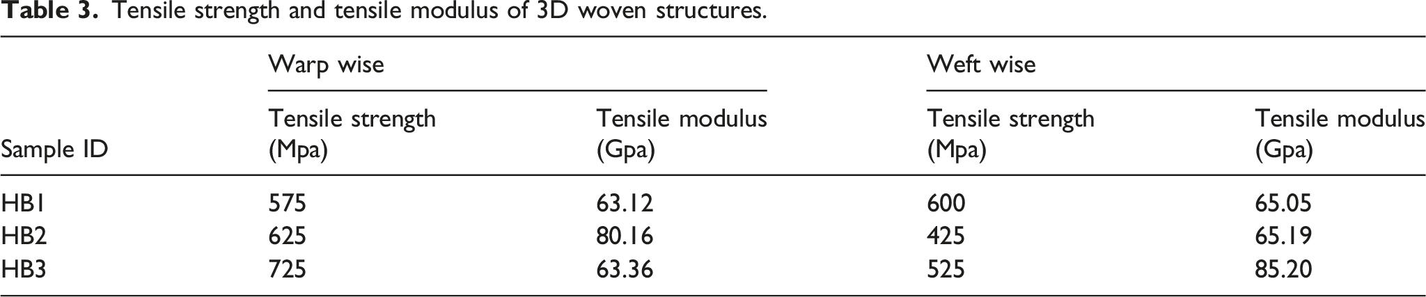
Comparing the three samples, a significant improvement in tensile strength and tensile modulus in both the warp and the weft directions was observed for HB3 as compared to the other samples; the HB1 and HB2 variations in the weft strength and modulus were intermediate to the extreme values observed in the three samples.
Statistical analysis
The effect of 3D woven structures on tensile strength significance was investigated using the Tukey comparison tool within a one-way ANOVA framework. In this context, the p-values were utilized to determine whether the specific factor had a significant or non-significant impact. A p-value below 0.05 indicated a significant effect of the woven structure, while a value exceeding 0.05 indicated a non-significant effect. The tensile strength results obtained from the developed samples, both in the warp-wise and weft-wise directions, demonstrated the significance of the 3D woven structure. This assertion was based on the observation that the p-values for both warp and weft directions were less than 0.05. In essence, modifications to the interlaced patterns resulted in variations in the tensile strength along both the longitudinal (warp) and transverse (weft) axes. Moreover, the coefficient of determination, commonly represented as R-squared (R-sq), quantifies the proportion of variance in the dependent variable that can be accounted for by the independent variables in the model. A greater R-squared value signifies an enhanced model accuracy, as it more effectively reflects the variability in the response variable. The obtained values for the tensile strength results were 0.00 for the p value and 99.97% for the R-squared value. The Tukey simultaneous plot in Figure 4 displays the relationship between tensile strength in the warp and weft directions. It is evident from the plot that all pairs of variables demonstrate non-zero values within their respective ranges, so confirming the substantial impact of these variables on tensile strength. Tukey simultaneous plot of 3D woven structures for tensile strength.
Stiffness test
To assess the stiffness of the fabric, a stiffness test was conducted using a fabric stiffness tester. Stiffness test results are mentioned in Figure 5, the graph indicates that the HB-1 (P) structure has a 2515 gf stiffness value which is the highest of the other two samples, it is due to higher crimps percentage in warp yarn and the presence of stuffer yarn in HB-1 (P) structure has also made it stiffer and more compact structure. The application of force onto the fabric necessitates a greater magnitude of force to traverse the stiffness instrument for stiffness measurement. This is mostly attributed to the inclusion of stuffer yarns within the fabric. The HB-3 (P) has a stiffness value of 2122 gf, while HB-3 (T) has a stiffness value of 2157 gf, which is slightly higher than the HB-3 (P) structure. HB-3 structure almost shows the same behavior in warp and weft direction due to double yarn on both the top and bottom sides of the structure. The results show that the HB-1 (P) structure required the highest force to bend as compared to the other two samples. HB-2 structure, warp-wise and weft-wise, showed the least stiffness due to a smaller number of ends and pick densities, so the structure will be less compact than the other two structures. According to Figure 5, the results showed that the HB-1 (P) structure in the warp direction required the highest force to bend compared to the other two structures. Stiffness testing results of 3D woven structures.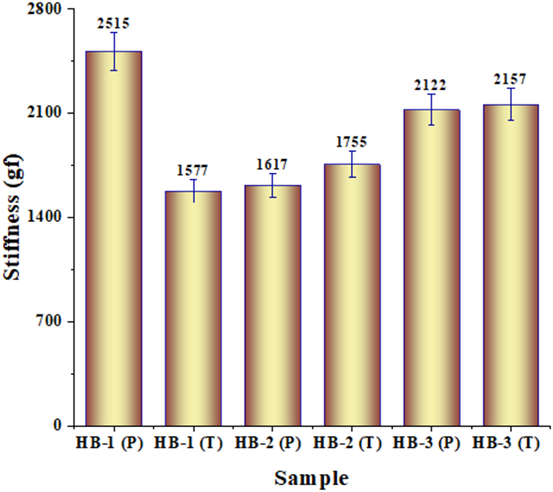
Similar trends were observed in studies on bast yarn fabrics by (5) and (6). Jabbar et al. found that fabrics with stuffer yarns exhibited higher stiffness due to the additional support provided by the yarns, consistent with our HB-1 (P) results. Muhamood et al. noted that hybrid woven structures with varied yarn densities showed differing stiffness values, with more compact structures demonstrating higher stiffness, which aligns with our findings for the HB-1 and HB-3 structures.
Statistical analysis
The statistical significance of the impact of innovative 3D woven structures on fabric stiffness was examined using a one-way ANOVA with Tukey comparison. The p-values were employed as markers, with a p-value below 0.05 denoting statistical significance, whereas a value above 0.05 showed lack of statistical significance. The examination of fabric stiffness results indicated a substantial impact of the woven structure, as evidenced by a p-value of 0.000, which falls below the conventional threshold of 0.05. This suggests that modifications in the interlaced arrangement of fibers also resulted in variations in the rigidity of the textile material. In addition, the model summary incorporates the coefficient of determination, usually known as R-squared (R-sq), which measures the extent to which the variables that are independent in the model can explain the variability observed in the dependent variable. A higher R-squared value signifies a model with increased accuracy, as it more proficiently captures the variability present in the dependant variable. The p-value and R-squared value for the structure stiffness results were found to be 0.00 and 99.88%, respectively. Figure 6 displays the Tukey simultaneous plot illustrating the structure stiffness for HB-1 (TT), HB-2 (LL), and HB-3 (LL). The data presented in Figure 6 demonstrates that out of all the interval pairs examined, only two pairs, specifically HB-2 (LL) (P) - HB-1 (TT) (T) and HB-3 (LL) (T) - HB-3 (LL) (T), exhibit a range that encompasses the value of 0. This suggests that these two pairs lack practical significance. On the contrary, all other pairs demonstrate non-zero mean values within their respective ranges, indicating their practical significance. Tukey simultaneous plot of 3D woven structures for fabric stiffness.
Puncture test
The force versus extension curve is shown in Figure 7. It is observed that HB-3 woven structure is more puncture resistant than HB-1 and HB-2 structures. It is because, in HB-3 (LL) structure, double yarn is present on both the top and bottom sides of the structure. When the stylus touched the fabric double yarn resists the stylus from penetrating the fabric thus, more force is required for penetration. Also, more interlacement points of warp yarn have made this structure more compact and stiffer than HB-2 (LL) structure. HB-2 structure has shown the least puncture resistance due to fewer warp and weft thread densities, which made this structure less compact, so stylus penetration was easier compared to HB-1 (TT), and HB-2 structure. Higher puncture tolerance was observed in HB-3 (LL) structure as compared to HB-1 (TT) and HB-2 (LL). While in the case of hybrid structure HB-1 (TT), it showed the least resistance to HB-3 (LL) structure while more resistance to HB-2 (LL) structure, it is because HB-1 (TT) has more compact as compared to HB-2 (LL). Force versus extension curve of 3D woven structures during puncture test.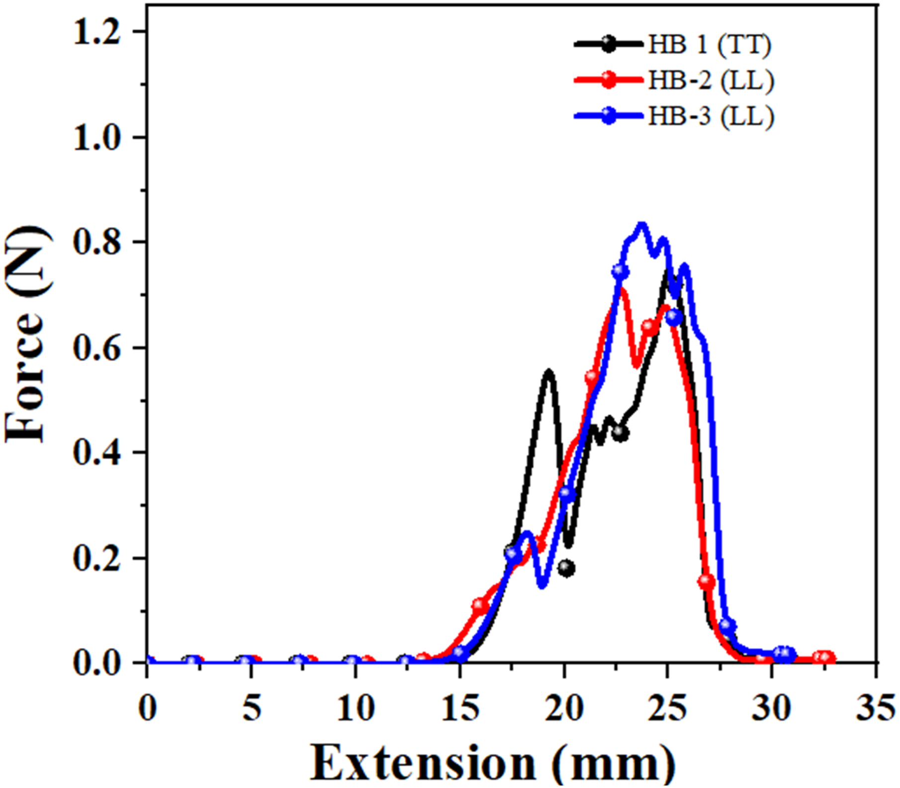
Puncture resistance testing results.

Our puncture resistance results are consistent with findings by (7) and (3). Kashif et al. demonstrated that hybrid structures with higher yarn interlacements exhibited increased puncture resistance, similar to our HB-3 results. Umair et al. observed that fabrics with higher compactness and stiffness showed better puncture resistance, aligning with the performance of our HB-3 structure
Statistical analysis
The study employed a one-way analysis of variance (ANOVA) with Tukey’s post hoc test to examine the statistical significance of innovative 3D woven architectures in relation to puncture resistance. The statistical analysis of the puncture test findings revealed a strong indication of the woven structure’s high relevance, as evidenced by a p-value of 0.000, which falls significantly below the conventional threshold of 0.05. This implies that modifications in the interlaced arrangement significantly affect the puncture resistance characteristics. In addition, the model summary included the coefficient of determination, commonly referred to as R-squared (R-sq), which quantifies the proportion of variance in the response variable that can be accounted for by the model. A greater R-squared value signifies an enhanced model accuracy, as it more effectively reflects the variability in the response variable. The puncture test yielded a p-value of 0.00 and an R-squared value of 96.06%.
Figure 8 displays the Tukey simultaneous plot representing the puncture test conducted on HB-1 (TT), HB-2 (LL), and HB-3 (LL). The data presented in the Figure 8 indicates that there is just one pair of intervals, namely HB-2 (LL) (P) - HB-1 (TT) (T), which encompasses the value of 0. Consequently, this particular pair can be considered statistically insignificant. On the other hand, it is worth noting that all other pairs demonstrate non-zero mean values within their respective ranges, indicating their practical significance. Tukey simultaneous plot of 3D woven structures for puncture test.
Tear strength
The tear strength parameter is utilized to evaluate the structural durability in terms of its ability to withstand tearing or damage at susceptible locations during the course of usage. The mobility of the yarns inside the fabric’s structure affects a fabric’s tear resistance. Due to their reduced mobility, plain textiles had a poor tearing strength as compared to the longer floats. Fewer interlacement points of yarn results in more tear strength. Figure 9 depicts the relation of tear strength with 3D woven structures of HB-1, HB-2, and HB-3 in warp and weft directions. The results indicated that the HB-1 (P) hybrid structure has the maximum tear strength compared to all the other structures, as the binder yarn crossed over and under the weft yarns in the thickness direction to hold the structure together such that a bundle of yarns would be formed. As a result, a higher force is required to tear it. Therefore, by increasing the structure’s floats, the structure’s tear strength also increases. The highest tear strength is shown by the HB-1 structure in the warp direction, which is 294 N, the same sample has the highest float length as compared to other structures. While minimum tear strength is shown by the HB-2 structure in both warp and weft directions is 256N and 240 N, respectively. HB-3 (P) showed the least tear strength as compared to HB-1 (P) structure due to more interlacement points. There is not much significant difference in HB-1 (P) and HB-3 (P) structures due to the presence of double yarn at the top and bottom in HB-3 (P) structures, which resists the knife from tearing the fabric, so more force is required to tear the fabric. Tear strength results of 3D woven structures.
Our tear strength results align with those of research by (8) and (9). Ullah et al. reported that structures with fewer interlacements and higher float lengths showed better tear resistance, similar to our HB-1 results. Maqsood et al. found that hybrid woven fabrics with binder yarns exhibited higher tear strength due to increased structural integrity, consistent with our findings.
Statistical analysis
The Tukey one-way comparison tool, which is a component of the analysis of variance (ANOVA) framework, was utilized to assess the statistical significance of 3D weaved structures on tear strength. The p-value functions as a metric for determining the statistical significance of a component. When the p-value is below the threshold of 0.05, the factor is regarded as statistically significant; conversely, if it surpasses 0.05, the factor is declared not statistically significant. The tear strength data obtained from the investigation, both in the warp-wise and weft-wise directions, demonstrated a p-value of 0.000, indicating statistical significance at a significance level of 0.05. This suggests that modifications in woven structures have a substantial effect on tear strength.
In addition, the model description of the tear strength data included the coefficient of determination, commonly referred to as R-squared (R-sq). This percentage represents the model’s ability to accurately account for the variability observed in the response variable. A greater R-squared value signifies a model of higher accuracy, as it provides a more comprehensive understanding of the variability in the answer. The tear strength data yielded a p-value of 0.00 and an R-squared value of 95.85%.
Figure 10 illustrates the Tukey simultaneous plot for tear strength, encompassing the woven structures HB-1, HB-2, and HB-3. The Tukey plot displays a confidence interval that reveals the presence of three pairs of intervals: HB-2 (LL) (P) - HB-1 (TT) (T), HB-3 (LL) (T) - HB-1 (TT) (T), and HB-3 (LL) (T) - HB-2 (LL) (P). These intervals all contain the value of 0 within their respective ranges. This implies that these intervals have little to no practical significance. In contrast, it can be noticed that all other pairs exhibit mean values that are not equal to zero within their respective ranges, thereby highlighting their practical significance. Tukey simultaneous plot of 3D woven structures for tear strength.
The SEM images of the failed specimens for HB1, HB2 and HB3 show the fiber failure mechanisms under the action of tear force in detail as shown in Figure 11. For HB1, the SEM micrograph shows a high degree of fiber breakage and pull-out which are characteristics of a brittle failure mechanism. The images indicate that fibers in the case of HB2 are seen to be breaking and tearing as opposed to the case of HB1, thus indicating a marginally more ductile failure. The SEM images of HB3 show much fiber pull-out and debonding, which indicates the material’s capacity to store energy through these modes. These images as a whole demonstrate the manner in which the 3D woven structures fail under tear forces and, therefore, provide further insight into their mechanical properties. SEM images of the failured samples (a) HB1, (b) HB2 and (c) HB3.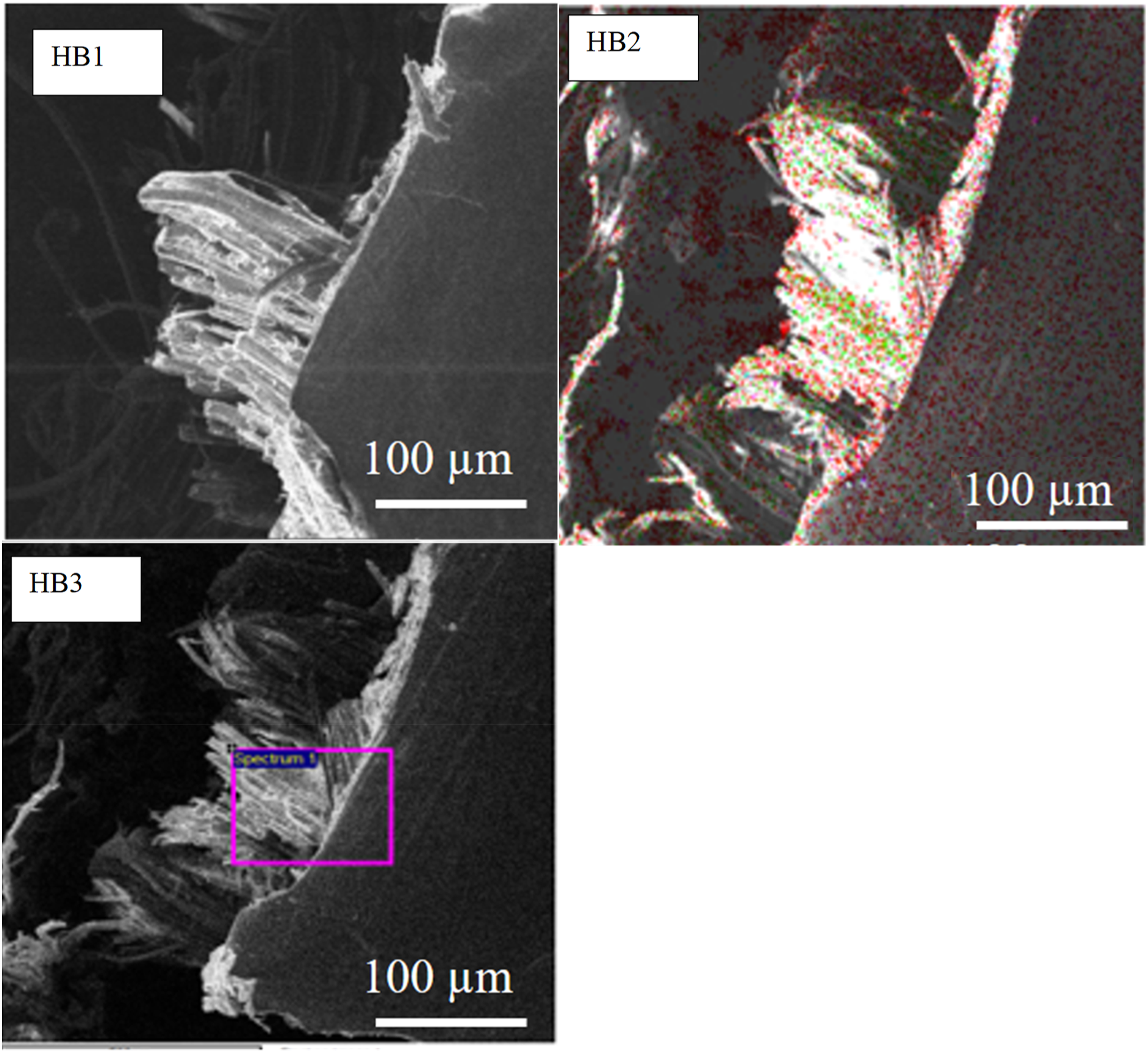
Conclusions
This study involved the development of three distinct variations of 3D woven structures, namely HB-1 (TT), HB-2 (LL), and HB-3 (LL), using hemp spun yarn on a dobby loom. To assess the mechanical properties of the developed samples, a number of mechanical tests were conducted such as stiffness, tear, puncture and tensile strength. The stiffness test results indicates that, the hybrid structure HB-1 (combination of binder and stuffer yarns) showed 55.53% higher value of stiffness than the rest of the sample. While the tear strength results showed that the HB-1 (TT) structure showed 16.40% higher tear strength than the HB-2 (LL) structure. However, in the puncture test, the HB-3 (LL) structure showed 16.4% higher resistance to stylus penetration as compared to other samples. The HB-3 structure has double yarn on both the top and bottom, which resists the stylus from penetrating the fabric; thus, more force is required for penetration The HB-3 (LL) design exhibited a considerable advantage in terms of tensile strength along the warp direction, surpassing the other configurations by a significant margin of 25.75%. The remarkable durability of this structure can be attributed to the absence of binder yarn, resulting in a low crimp percentage. In contrast, the HB-1 (TT) hybrid structure in warp diection showed the least tensile strength due to the more crimp percentage in warp yarns. For s. e. In addition, the obtained results were subjected to a comprehensive statistical analysis employing the One-way Analysis of Variance (ANOVA) method, followed by Tukey’s post hoc comparison. The ANOVA analysis, specifically utilizing the Tukey method, provided compelling evidence to support the notion that the introduction of unique 3D woven structures had a substantial influence on various outcome measures, including tensile and tear strength, fabric stiffness and puncture resistance. Overall, it can be concluded that 3D woven HB-3 (LL) structure showed optimum values of different mechanical tests and can be preferred for high-tech applications.
Future research should focus on preparing and analyzing composites using the developed 3D woven structures, investigating their long-term durability, and examining the impact of different environmental conditions on their mechanical performance. Additionally, optimizing weave patterns to enhance specific mechanical properties and exploring the use of bio-based fibers for sustainable applications are crucial areas for further study.
Footnotes
Acknowledgements
The authors extend their appreciation to Princess Nourah bint Abdulrahman University Researchers Supporting Project number (PNURSP2024R736), Princess Nourah bint Abdulrahman University, Riyadh, Saudi Arabia.
Author contributions
MMS: investigation, conceptualization, methodology, - writing, editing, visualization, resources; MIK: investigation, software, validation, - writing, editing; TU: investigation, writing, editing; HMFS: investigation, editing; ZAR: resources, editing, supervision; MU: conceptualization, resources, editing, - acquisition, supervision; MA: validation, Funding, editing, software, investigation; EF: resources, editing, methodology, software.
Declaration of conflicting interests
The author(s) declared no potential conflicts of interest with respect to the research, authorship, and/or publication of this article.
Funding
The author(s) disclosed receipt of the following financial support for the research, authorship, and/or publication of this article: The research was funded by Princess Nourah Bint Abdulrahman University Researchers Supporting Project number (PNURSP2024R736), Princess Nourah Bint Abdulrahman University, Riyadh, Saudi Arabia.