
Abstract
Additive manufacturing (AM) is rapidly emerging in high performance applications such as army ground vehicles, automotive and transportation. However, the response of AM parts/components to extreme loading such as high velocity impacts is less studied. In this work, the performance under ballistic impact of AM panels is evaluated using a medium velocity gas gun, generating projectile velocities up to 400 m/s. The preferential print orientation properties are considered in order to evaluate whether the panels exhibit isotropic or anisotropic behavior under impact. Surface morphology is investigated by milling the beads smooth on samples and comparing the impact on as-printed samples to those that are smoothed. The effect of nickel chromium micron (nichrome) wire embedded in the AM panels (during print) of polycarbonate-carbon fiber (PC-CF) and polycarbonate-glass fiber (PC-GF) are explored. Thermoplastic polyurethane-acrylonitrile butadiene styrene/carbon fiber (TPU-ABS/CF), Acrylonitrile butadiene styrene-carbon-fiber (ABS-CF) AM samples absorbed >50% of the impact energy. The ballistic performance was noted to be in the following order – ABS-CF > TPU-ABS/CF > PC. Scanning electron microscopy (SEM) was conducted to study the interface between the nichrome wire and the polymer-fiber matrix. This work is the first of its kind exploring into the capabilities of AM panels as ballistic materials. This study leads the way for developing AM panels that are easily manufactured and exhibit superior ballistic resistance.
Introduction
The need for light weight and geometry efficient panels that can withstand ballistic impacts is not new. 1 The ease of manufacturing, cost and performance dictate the viability and implementation of ballistic panels. AM panels provide an ease of manufacturability in a multitude of thermoset and/or thermoplastic matrices. Synthetic fibers offer the advantage of high specific moduli and manufacturability.2-4 The motivation for lightweight and easily producible ballistic panels and personnel armor is of major interest in military, transportation and infrastructure applications. 5
AM polymer composites can be printed using either thermoplastic or thermoset polymers. In AM thermoplastics fused deposition modeling (FDM) technique, a heated nozzle melts and deposits polymer-fiber blend onto a surface, layer-by-layer. 6 Thermoplastic material extrusion commonly has voids; due to the inclusion of the reinforcing fibers, hence interlayer bonding is decreased.6,7 Big Area Additive Manufacturing (BAAM) uses a feedstock of pellets instead of a filament, reducing processing costs. BAAM offers build volumes and output rates orders of magnitude higher than typical extrusion methods. 8 The larger build volumes result in high-temperature-gradients between adjacent layers, and hence higher residual stress. 8 The addition of carbon fiber in BAAM improves the strength, modulus, dimensional stability and thermal conductivity of the material. 8 Use of AM/BAAM composites as ballistic materials is an emerging area of study.
Literature review
Textiles and woven fabrics have been used as ballistic protection for personnel and vehicles effectively; subsequently, the failure modes of woven fabrics are well documented.9,10 The ballistic impact response of woven fabrics are governed by the primary yarn, secondary yarn and formation of a conical transverse wave.9,10 The strain to failure percent of the fibers dictates the energy absorbed in primary yarns.8,10 Failure of primary yarns occur when the tensile strain caused by the projectile elastically deforming the primary yarn becomes greater than the fibers capabilities.
The failure mode under ballistic impact in AM parts/components and composites is not well studied. Integrated wires and sensors in textiles are of increasing importance, however no studies are reported on the ballistic impact on AM composites with such embedment to our knowledge. There have been numerous investigations on damage propagation and response of fabric composites to ballistic loading.9,10 It has been shown that energy absorption in composites is dictated by several factors such as, compression of the target directly below the projectile and in the region surrounding the impact zone, conical deformation of distal face of the target, delamination and matrix cracking, shear plugging and friction between the projectile and the target. 9
Fragmentation is the result of multiple events and results in reduction of load bearing capacity due to impact and progressive damage. 11 Fragmentation or spall can be observed when the exit point of the projectile takes with it a large mass of material. For this study, spall will be considered if the exit diameter is at least 4-5 times that of the 9 mm projectile or roughly >2.5 cm. Polycarbonates, acrylonitrile butadiene styrene (ABS), polylactic acid matrices all exhibit spall. Spall formation and ejection on the distal side of the panel is not desirable, these fragments become secondary projectiles themselves with sufficient velocity.
Several studies have reported full-field monitoring sensors in composite laminates for process and structural health monitoring in lieu of strain gages.12-14 These studies have used processes such as autoclave molding, vacuum infusion, resin transfer molding etc. Vaidya et al. investigated embedded layers of sensors called S.M.A.R.T (
There are no studies with embedded full field sensor(s) during AM. The BAAM process lends itself to complex shape manufacturing, however there is uncertainty about voids, overt pores and debonds which could influence the part performance. This paper considers a range of AM variants in terms of material constituents and some incorporating nichrome wire during the BAAM process. These variants have been systematically investigated for their ballistic behavior at 400 m/s impact velocity. The results and mechanisms of the ballistic performance ‘with’ and ‘without’ the nichrome wire for any differences in perforation or energy absorption mechanisms were evaluated and presented here.
Materials and Methods
Panels printed on the BAAM at Oak Ridge National Laboratory (ORNL) Manufacturing Demonstration Facility (MDF) were used for ballistic testing. The panels were made using extrusion-deposition on the BAAM as shown in Figure 1.
16
Typically the BAAM prints are done as hexagon shapes, from which test coupons and plates are extracted. Schematic for the hexagon printed and dimensions for samples used in the mechanical characterization. Five specimens were harvested in each.
Summary of geometry and nomenclature of the ballistic test specimens.

*PC *(Polycarbonate) – SABIC LexanTM.
*CF (Carbon Fiber) Toray T-300, GF (Glass Fiber), Owens Corning.
*Thermoplastic Polyurethane-Acrylonitrile butadiene styrene/Carbon Fiber (TPU-ABS/CF)- Custom compounded at Techmer PM, 30 weight percent carbon fiber.
*Acrylonitrile butadiene styrene-carbon-fiber (ABS-CF), Custom compounded at Techmer PM, 30 weight percent carbon fiber.
The PC panels “with wire” had 20 weight (wt).% carbon fiber loading (PC-CF) and 20 wt.% glass fiber loading (PC-GF) (Techmer PM LLC (Clinton, TN, USA)), see Table 1. Both materials were dried for 4 hours at 90°C using a dryer (Dri-Air Industries Inc., East Windsor, CT, USA). Nichrome alloy wire with Nickel 60%, Chromium 16%, and Iron 24%, and a diameter of 0.508 mm with electrical resistivity of 0.126 ohms-m (McMaster-Carr, Cleveland, OH, USA) was used during the co-extrusion AM process. The layer height was 3.81 mm, and the layer width was 13 mm.
The panels were cut to 15 cm × 15 cm to fit the target carriage for the gas gun. AM panels of each composition were milled to remove the typical beaded finish from the BAAM, while some were left “as printed,” see Figure 1. The effect of the surface finish relative to bead orientation was investigated by rotation of the panels by 0° and 90° on the surfaced and “as-printed” panels.
The AM panels were tested using the medium velocity gas gun at the University of Tennessee-Knoxville’s Fiber and Composites Manufacturing Facility (FCMF). The medium velocity gas gun uses helium as a propellant gas and nitrogen to initiate the actuator. A single projectile barrel was used for this study and has a length of 4.6 m and a diameter of 38.1 mm. The pressure vessel can be charged up to 1.4 MPa, varying the charge of the pressure vessel allows for control over the velocity of the projectile. The gas gun uses two Oehler M35 chronographs, paired with two Oehler skyscreen III photodetectors. The detector spacing is set at 60 cm between the start and stop detectors.
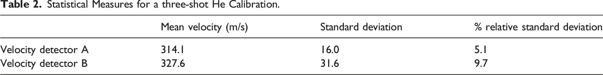
The gas gun was fired and calibrated over four shots, from 400 - 900 kPa to obtain a calibration curve shown in Figure 2. Table 2 provides the statistical variation for the projectiles fired in this gas gun. It is assumed that the expansion of the gas is fast enough that heat transfer is negligible, i.e., the process is adiabatic.
17
The gas gun parameters were kept constant for all materials initially and then varied based on observation of impact and damage assessment. The velocity was measured “before” the strike face of the target and upon exit (if applicable). Energy absorption is the main attribute of ballistic panels, but other factors such as layer orientation, bead size, interface between printed beads etc. are contributing factors as well. These factors will be discussed for AM panels simultaneously with damage mode assessment with limited comparison to ballistic performance of woven fabric composites. Gas gun calibration for striking velocity versus gas pressure. This helped set the test conditions for different velocities of interest. Calibration over a 500 kPa range is done to show the performance of the gas gun in the velocity range of interest. Statistical Measures for a three-shot He Calibration.
AM panels listed in Table 1 were evaluated prior to impact using ultrasonic nondestructive evaluation (NDE) prior to impact. Post-impact NDE assessment was done on the AM panels to ascertain the extent and mechanisms of degradation due to impact.
Results and Discussion
The results and discussion herein are presented to compare the performance of the AM panels from Table 1 and compared to woven fabrics.
First, PC-CF/GF (“without” wire) samples were compared to their PC-CF/GF “wire” counterparts and the other AM panels. The addition of the nichrome wire in the PC-CF/GF was analyzed to evaluate- (a) extent of bonding between the composite-nichrome wire interface; (b) effect of nichrome wire on damage propagation/energy absorption; and (c) void propagation from embedding the nichrome wire. Second, preferential print was measured by configuring three panels with their as-printed beads along the x-axis and three panels rotated 90° (i.e., along “y-axis”).
Figure 3 illustrates a typical ballistic response of AM panels. The failure was observed to be primarily through compression at the loading zone. The first few layers fail due to shear plugging and the undamaged layer(s) absorb energy through the thickness, creating a cone-shaped deformation.
9
Scale bar in mm. Exit points of (a) PC-GF ‘wire’, (b) PC-GF ‘without wire’, (c) ABS-C, (d) PC-CF ‘without wire’, (e) ABS-CF, (f) TPU-ABS/CF. (a–e) show spall on the backside of the panel. (c) ABS-CF shows the largest amount of spall, while (f) TPU-ABS/CF exit point is barely visible.
Figure 4 illustrates the energy absorption as a function of impact energy. In the figure, PC-GF/CF “wire,” PC-GF/CF (no-wire), 16S/R, and 8S/U (woven fabrics) are included for comparison. In Figure 4, woven fabrics have triangular symbol, AM specimens are dots symbol, ABS-CF has a square symbol. For woven fabric panels, the number (8 or 16) is the number of plies, S is ultra-high molecular weight polyethylene (Spectra©), U is unrolled and R is rolled
18
grade. PC-GF/CF ‘wire’, PC-GF/CF, 16S/R, and 8S/U woven fabrics for comparison, woven fabrics have triangular markers, AM specimens are dots, ABS-CF has a square marker due to its exceptional performance.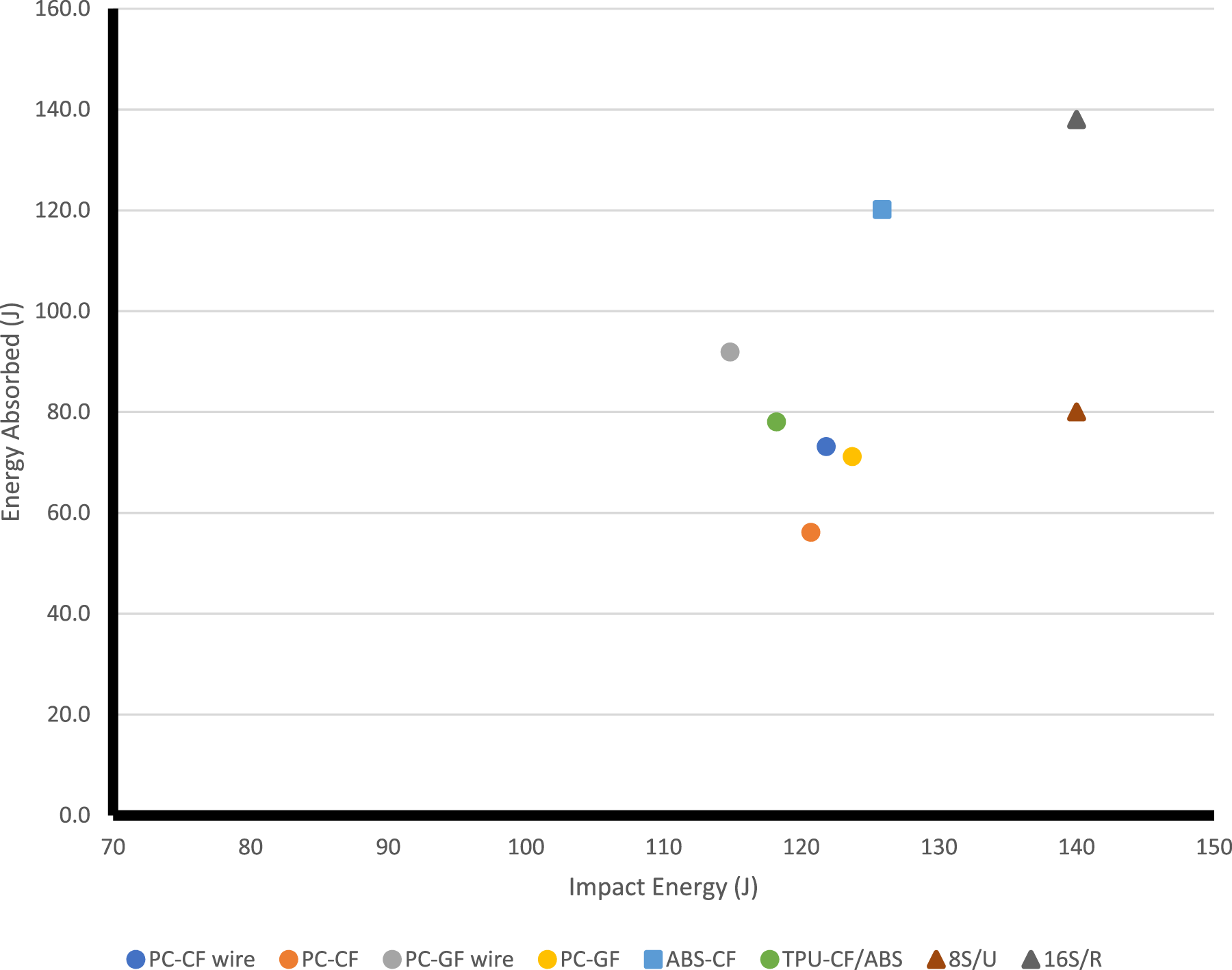
PC-GF outperforms PC-CF in energy absorbed by 15–20 J and is comparable to PC-CF “wire” in absorbing around 70 J of energy. PC-GF “wire” outperforms all PC based panels in energy absorption ranging from 10-50 J. TPU-ABS/CF performs similarly to 8S/U fabric at comparable impact energies. 16S/R outperforms all specimens at the upper range of impact energies.
In PC-CF/GF “wire” the nichrome wire directly impacted acts much as a primary yarn of a fabric composite,
9
see Figure 5. The SEM images of the cross section of the PC-CF “wire” at the exit point of the panel. The diameter of large voids is roughly 60–80% of the dimeter of the nichrome wire. The nichrome wire deforms elastically until the overall strain exceeds the failure strain of the wire. SEM of PC-CF ‘wire’. (a) Cross section of exit point for PC-CF ‘wire’ showing the nichrome wire impacted by the projectile; (b) Red arrow indicating the matrix-nichrome wire bonding and yellow arrows showing voids in the PC-CF matrix; and (c) Nichrome wire shows crack propagation along the wire. Remaining PC can be seen on the nichrome wire indicating adhesion between the PC and the wire.
Effect of nichrome wire on PC specimens
PC-CF
Figure 4 displays the Energy absorbed versus Impact energy. Three woven fabrics are presented for comparison. TPU-ABS/CF performs similarly to 8-ply Spectra© rolled, absorbing 57.6% of the impact energy. 8-ply Spectra rolled fabric absorbs 57.2%. Spectra was impacted with 140 J of energy while TPU-ABS/CF was impacted with ∼133 J. In Figure 4, PC-CF “wire” and PC-GF “wire” absorb over 50% of the impact energy. Polycarbonate with added nichrome wire absorbs energy similarly, i.e., more than 50%, to Spectra© with eight plies unrolled.
Previous studies9,10 have shown that the energy absorption mechanisms in woven fiber composites is in the form of cone formation influenced by transverse wave propagation, delamination between layers, elastic deformation of the primary yarns and tensile failure of the primary yarns. The damage mechanisms of the AM panels “with wire” specimens were comparable to woven fabrics.
The nichrome wire is pulled out of the composite matrix until it ruptures, and crack propagation is observed along the wire. The deformation of the nichrome wire and pull-out shows that energy is dissipated through the nichrome wire to the PC-CF substrate causing debonding of the wire from the substrate. The crack propagation along the wire is attributed to the longitudinal, in-plane wave traveling along the nichrome wire progressively debonding the PC-nichrome wire interface.
The difference in the nichrome wire and woven fabrics becomes evident. In woven fabrics the energy is transferred to the fibers via a mechanical interlock (i.e., weave type). For nichrome wire AM panels, the energy transferred to the nichrome wire was from the PC matrix via the distinct interface of PC and nichrome wire.
Figure 5 shows a nichrome wire that acts as a “primary yarn” for PC-CF “wire.” PC-CF “wire” outperforms PC-CF (“no wire”) in energy absorbed by 21 J, ∼14% more energy than PC-CF “without wire.” Figure 5 shows that the AM panels “with wire” are superior in absorbing energy under high velocity impacts, anywhere from 10-40 J higher than their “without wire” AM counterparts. The panels with nichrome wire contained large degree of porosity and structural defects; yet, outperformed traditionally extruded PC-CF “without wire” and PC-GF “without wire” parts in terms of absorbed energy. For PC-CF “without wire” ∼20 J or 14% drop in energy absorbed, compared to PC-CF “wire” was observed.
PC-GF
Average impact velocity, energy absorbed and percent energy absorbed.

*PC-CF ‘wire’ represents Polycarbonate-carbon fiber specimens with embedded nichrome wire.
*PC-CF ‘without’ represents Polycarbonate-carbon fiber specimens without embedded nichrome wire.

PC-GF ‘wire’ SEM. (a, c) show a nichrome wire that was impacted directly. (c) shows the fiber rupture, adherence of PC to the nichrome wire and the crack propagation along the nichrome wire. (b, d) show the same nichrome wire where the wire emerges from the PC-GF matrix. (d) interface between nichrome wire and PC-GF matrix with fiber disruption.
Comparable to the PC-CF “wire,” the PC-GF “wire” shows damage propagation laterally along the nichrome wire observed as matrix cracking; indicating that the nichrome wire acts much like a primary yarn for PC-GF “wire” as well.
Glass fibers absorb more energy before they fail under high strain. 9 The addition of nichrome wire combined with the robust ballistic properties of GF make an effective ballistic material.
The effect of surface topography and panel orientation was investigated for PC-GF “without wire.” Table 3 shows the average energy absorbed for PC-GF “without wire” was 71.1 J. The average energy absorbed for smooth surfaces was ∼73 J, average energy absorbed for “as-printed” surfaces was ∼69 J. No visible change was seen in exit site cone formation for smooth surfaces when compared with “as-printed” surfaces. The factors that influence energy absorption are not susceptible to surface topography or panel orientation. This can be attributed to the ballistic event being highly localized and less influenced by panel orientation.
AM panels “without wire”
Fragmentation present major hazards to the individual(s) and/or equipment. Fragmentation was observed to be highly dependent on the type of the AM material. Figure 3 illustrates the damage mode of representative AM panels. Figure 3(c,e) shows ABS-CF which shows ∼100 mm area of fragmentation exiting as one piece, while TPU-ABS/CF has a barely visible exit point. Figure 7 is a SEM image for ABS-CF and Figure 8 shows the TPU-ABS/CF on the exit side, respectively. Figure 3 (f) shows a 2–3 mm damage on the exit site for TPU-ABS/CF which demonstrates that it does not exhibit a cone like deformation on the backside. Table 3 summarizes the average energy absorbed for all AM panels. SEM of ABS-CF. (a) The interlaminar damage propagation at the terminal site can be seen. (b) 5x more magnified view of the red box in (a). The extent of the intralaminar cracks can be seen in (b). ABS had 100 mm × 20 mm portions of spall blowout. Figure 2 C shows the exit site that was cross sectioned for Figure 6. TPU-ABS/CF SEM of ballistic path. The orange arow indicates the direction the projectile traveled. (a) The exit point of the projectile and (b) is the impact point. From (b) to (a) a widening of the ballistic path can be observed. TPU-ABS/CF had a 2–3 mm gash at its exit site.

ABS-CF
ABS-CF absorbed 94.5% energy, more than any other variant listed in Table 3. Figure 3 (c) shows the extent of the damage at exit site. Damage through the thickness can be seen in Figure 8 (b). Energy was dissipated through the impact zone and damage propagated through the thickness.
Figure 8 (b) shows a crack emanating from the bulk of the panel and terminating at the exit site. The ABS-CF panels had 100 mm × 20 mm portions of spall blow out, see Figure 3 (c). These fragments absorbed energy failing at their periphery and breaking away from the bulk. The strong interfacial strength of ABS-CF 19 allows for portions to stay intact and dislodge from the bulk absorbing ∼37–50% more energy relative to PC-CF/GF systems “without wire,” respectively. The rigidity of ABS-CF means it absorbs more energy before yielding, but it fails catastrophically producing spall 10–20% larger than PC specimens. In rigid AM panels, the backside cone formation produced by transverse wave propagation, appears to dominate the exit site and damage mode.
TPU-ABS/CF
TPU-ABS/CF is more viscoelastic than the other variants due to alternating hard and soft segments. 20 Table 3 illustrates that TPU-ABS/CF absorbed 7–20% more energy from ballistic impacts than PC-GF/CF “without wire,” respectively. TPU-ABS/CF absorbed 5.3% more energy than PC-CF “wire” but 14% less energy than PC-GF “wire.” The PC-GF “wire” surpassed TPU-ABS/CF in percent energy absorbed. The failure at the projectile’s exit point is vastly different for TPU-ABS/CF compared to all other specimens.
Figure 3(f) Displays the exit location for TPU-ABS/CF was almost unnoticeable, no visible blow out or spall was observed. The projectile penetrated the composite and the material self-healed, leaving only a minor gash. The through-the-thickness path of the 9 mm spherical projectile was visualized from the cross-section at the impact location.
Figure 8 shows that the projectile did not travel linearly through the panel. The viscoelasticity of TPU offers a tortuous path for penetration, and redirects the path of the projectile. These mechanisms contributed to higher absorbed energy, elastic deformation and resisting blow out.
TPU-ABS/CF did not exhibit cone formation on the distal side of the target or spall blow-out and has a different energy absorption mechanism compared to stiffer, less viscoelastic polymeric matrices. 20 The TPU-ABS/CF appears to self-heal as evident from Figure 3(f).
Discussion
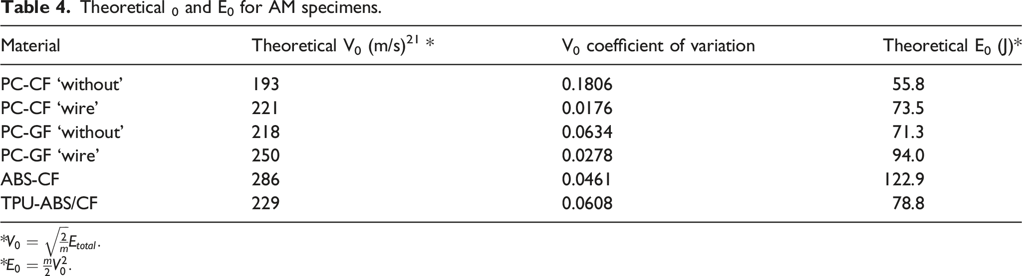
Theoretical 0 and E0 for AM specimens.
*
*
The AM samples exhibited a perforation on the strike face and different degree of back face damage. In general, the “wire” samples did not exhibit any adverse effect of the wire. Rather, they exhibited higher performance due to the catapult (or cone effect) witnessed in fabric composites. Comparison has been made to UHMWPE - 16S/R, and 8S/U which is an upper bound solution for continuous fiber/fabric composites. The AM specimens exhibited 16%–53% lower impact energy absorption compared to 16S/R (16-layer UHMWPE) while they had comparable response to 8S/U (8-layer UHMWPE), indicative of high toughness of AM samples even with short fibers in their composition. Damage was highly localized and there was no evidence of catastrophic delamination indicative of good interlayer bonding from the AM process.
PC-GF outperforms PC-CF in energy absorbed by 15–20 J and is comparable to PC-CF “wire” in absorbing around 70 J of energy. PC-GF “wire” outperforms all PC based panels in energy absorption ranging from 10-50 J. TPU-ABS/CF preforms similarly to 8S/U fabric at comparable impact energies. 16S/R outperforms all specimens at the upper range of impact energies.
Conclusion
The ballistic impact performance of BAAM printed plates was evaluated for a range of polymer matrices including Polycarbonate, Thermoplastic polyurethane-acrylonitrile butadiene styrene/carbon fiber (TPU-ABS/CF), Acrylonitrile butadiene styrene-carbon-fiber (ABS-CF). AM samples absorbed >50% of the impact energy, except for PC-CF.
For all AM plates, the failure was in the form of strike face perforation and fragmentation at the back surface. The size of the fragments varies based on the constituent materials. The ballistic performance was noted to be in the following order—ABS-CF > TPU-ABS/CF > PC.
Comparing PC-GF and PC-CF and “with and” “without” wire: PC-CF “wire” had 47% higher energy absorption than PC-CF no wire. PC-GF “wire” had 40% higher energy absorption over PC-GF no wire. PC-GF had 28% higher impact energy than PC-CF. TPU-ABS/CF had 59% higher energy absorption over PC-CF “no wire.” Ultra-high molecular weight polyethylene (UHMWPE) from literature for similar areal density exhibited 16% higher energy absorbed over the highest performing AM variant namely ABS-CF panels. For other variants, the different between UHMWPE and AM was ∼53% higher.
The ABS-CF has strong bonding between the constituents and fragments in substantial portions absorbing the greatest amount of kinetic energy of all composites tested, 94.5%. TPU-ABS/CF deflects fragments from the projectile through the thickness, i.e., steers it laterally off center. TPU-ABS/CF absorbs around 78% of the impact energy. Both, TPU-ABS-CF, and ABS-CF out preformed PC matrix regardless of “wire” or “no wire.”
The addition of nichrome wire to PC-CF and PC-GF bolstered ballistic resistance and energy absorbed. The nichrome wire has a direct role in absorbing energy when contacted directly by the projectile. Kinetic energy is dissipated coaxially along the wire into the polymer fiber matrix allowing for more energy absorption compared to neat counterparts. Glass fibers are advantageous in ballistic response owing to their high strain to failure rates as compared to carbon fiber. 9 PC-CF and PC-GF increased energy absorption by 14% and 17% respectively with addition of nichrome wire. TPU-ABS/CF and ABS-CF may benefit from the coextrusion method and addition of nichrome wire. AM/BAAM printed materials for ballistic protection is an exciting and emerging concept for embedded sensors in AM composites.
Footnotes
Acknowledgements
The authors gratefully acknowledge the SERVE: Shaping Experiential Research for Veteran Education Program at University of Tennessee for funding undergraduate veteran student researchers. The work presented herein was funded in part by IACMI-The Composites Institute, U.S. Department of Energy, Advanced Manufacturing Office (DOE AMO) under Award Number DE-EE0006926.
Declaration of conflicting interests
The author(s) declared no potential conflicts of interest with respect to the research, authorship, and/or publication of this article.
Funding
The author(s) disclosed receipt of the following financial support for the research, authorship, and/or publication of this article: This work was supported by the U.S. Department of Energy (DE-EE0006926).