
Abstract
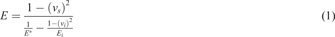
This paper deals with solving the problem of constructing two-level computational models relating the stress-strain state at the microscale to the stress-strain state of the structural component at the macroscale for layered polymer composite materials with unidirectional fiber stacking in a monolayer. The paper presents a two-level computational mechanical model of a ten-layer cross-ply fiberglass-reinforced polymer composite with (0/90) laying patterns. The model is based on microindentation data. The model is constructed using the finite element method. The constructed model has allowed us to predict the elastic properties of the composite and to calculate stresses at the microscale and macroscale levels of a specimen prior to fracture under tensile conditions. The elastic properties of the polymer composite material predicted by the computational model are compared with the properties obtained from real experiments. Calculated for fiberglass, the elasticity modulus and Poisson’s ratio are 31 GPa and 0.11, respectively. Similar elastic properties obtained from real experiments are 28 GPa and 0.10. The technique used in the paper can be applied to computational experiments with an actual structural component made of a multilayer polymer composite in order to determine the stress-strain state at the micro- and macroscale under external mechanical impact on the structure.
Keywords
Introduction
In the last two decades the line of research on creation and renovation of aerospace equipment using composite materials has become increasingly popular in modern aerospace engineering. In particular, these materials include polymer composite materials (PCM), which, in comparison with conventional alloys, have higher specific strength and corrosion resistance.1–3 The expansion of using polymer materials and polymer composite materials in modern technology is a global trend. At the same time, structural and functional materials being created must maintain their operability and survivability in extreme operating conditions under intense external mechanical, thermal, and other loads. Another global trend is to reduce the duration of developing finished products and manufacturing them according to individual technical requirements of a customer. The task of designing new polymer composites can be solved by conducting real experiments for composites with different reinforcement volume fractions and matrix compositions. These experiments require a lot of time and a large complex of real tests leading to large financial investments in the development of materials. On the other hand, methods of solid mechanics enable one to deal with issues concerning design and prediction of material properties depending on material composition and filler content, as well as production of materials and their behavior in a structure, in terms of computer simulation.4–9
The prediction of the elastic properties of polymer composite materials depending on the volume fraction of reinforcing particles is based on analytical and computational micromechanical models.9,10 Analytical models can be divided into five groups9,11,12: phenomenological, semi-empirical, elastic approximation, homogenization, and physically based models. As was shown earlier,9,10 analytical models of micromechanics allow us to predict elastic properties in polymer fiber composites with acceptable engineering accuracy. The models listed above, with the exception of physically based ones, cannot be used to construct coupled multilevel models due to the impossibility of applying boundary conditions obtained from another level. Physically based models are devoid of this disadvantage, and they allow us to explain the physical aspects of material deformation at all scale levels. 11 However, they are cumbersome and require a large number of material constants, whose determination is a nontrivial task. It is possible to use computational models as an alternative to physically based ones when predicting the elastic properties of a composite and its behavior at different scale levels depending on the effect on the structure. Earlier studies9,10,13–15 showed that computational models can accurately describe the behavior of composites under external thermomechanical influences. Using such models with the application of a multilevel approach to the description of the mechanical behavior of a composite material allows us to simulate its behavior at different scale levels, to identify stress concentration foci, and to determine conditions for the occurrence and development of microdefects in the material depending on the stress state type, the size and shape of the reinforcement at the micro level.8,16–20 Despite the possibility of simulating the stress-strain state in a material at different scale levels, multilevel models are used to solve the problems of determining the stress-strain state for a macroscopic volume with dimensions not exceeding several millimeters, this being certainly smaller than the actual dimensions of structures. As a result, the question arises about the possibility of constructing a computational model describing a real structure at several scale levels. Before multilevel models are used to simulate real structures, the approach used in the construction of multilevel models must be verified for specimens under simple loading conditions, such as tension and compression. Another important aspect worthy of attention when constructing a model is the correctness of obtaining experimental properties of material constituents.
Currently, the method of instrumental microindentation is widely used to determine the mechanical properties of material constituents at the micro level. This method is used to determine hardness, interphase zone, creep, damage, the elastic modulus, the material hardening curve, etc.21–30 The use of experimentally obtained mechanical properties at the micro level enables us to determine the mechanical properties of the constituents of a composite without information containing defects (pores, cracks) present in macroscopic test specimens among the sampling data. Another important issue in constructing multilevel deformation models is the determination of the size of a representative volume, which reflects ongoing processes associated with material deformation and fracture.31–33 The choice of the representative volume size is best made on the basis of real experiments since they take into account the real adhesive and cohesive properties of the structural constituents. It is easy to determine the representative volume size at the macro level by tension or compression tests; at the micro level, this procedure can be performed by the instrumental indentation technique, which was demonstrated on metal matrix composites.34,35
The aim of this study is to build, on the basis of micromechanical tests, a multilevel computational model of multilayer fiberglass, which would allow us to determine the properties of the composite at the macroscale level and to evaluate the stress-strain state in the layers of the composite at the macro- and microscale levels under external mechanical action.
Material and research methodology
The paper considers a ten-layer cross-ply fiberglass-reinforced polymer sheet with (0/90) laying patterns of reinforcing layers (Figure 1) as the model material. A prepreg consisting of unidirectional glass fibers and the EDT-69N epoxy binder36,37 is used as the initial material for producing the fiberglass-reinforced plastic. Vacuum molding was used in the manufacture of fiberglass. The curing cycle of the binder included creation of a vacuum and then heating of the prepreg package to 110°C at a rate of 1 °C/min followed by holding at this temperature for 1.5 h. At the end of holding, the package was heated to 130°C at a rate of 1 °C/min and then held for 3 h. This was followed by cooling under vacuum to a temperature of 60°C at a rate of at most 3 °C/min. After the required temperature had been reached, the vacuum was discharged, and the composite was cooled to room temperature. The layer layout for studying the polymer composite.
Thin section analysis shows that the volume fraction of fiberglass in the monolayer is 0.64 ± 0.03 (Figure 2). Fiberglass distribution in the polymer composite material.
The elastic characteristics of the polymer composite were determined in tensile testing of five specimens using an Instron 8801 servo-hydraulic testing machine. Strains were measured directly on the specimens in two directions by means of an Instron AVE non-contact video extensometer, which ensures the absence of additional external influences on the specimen surface. The specimens are shown in Figure 3. A tensile test specimen sketch.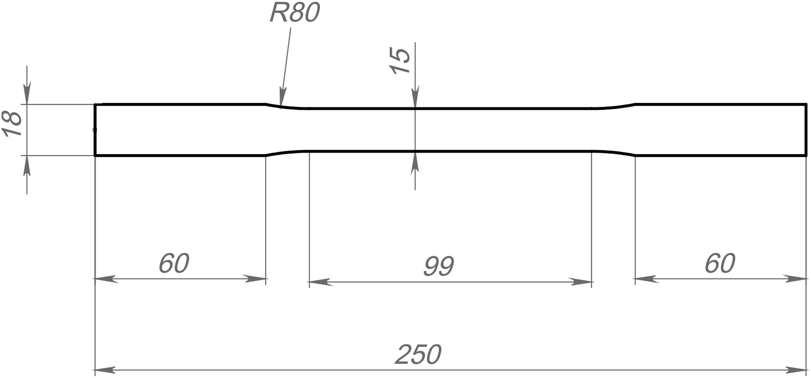
Indentation was performed by a Hysitron TI900 versatile complex designed for nanomechanical testing with the use of a Berkovich indenter. The indentation was performed on planar parallel surfaces, which had been obtained by ion etching enabling the properties of the structural constituents of the composite to be determined without introducing fragments and deformations into the surface as a result of mechanical preparation. Ion etching was performed with Linda SemPrep2 for 30 min at an accelerating voltage of 10 kV at the angle of specimen inclination to the ion beam equal to 7.
A technique for constructing a multilevel fiberglass model
The composite material under study is considered in terms of hierarchically organized systems,4,38–40 which are characterized by an interconnected reaction of adjacent scale levels as a result of external thermal deformation effects. Within the framework of this approach, the polymer composite material is presented in the form of two finite element models at the micro- and macroscale levels. The microscale level includes separate geometrically irregular structures, namely a matrix and reinforcing fibers with different laying directions, sizes, and distributions in volume (see Figure 1). Based on the structure of the material under study, the macroscale level is represented as a multilayer material with homogeneous (averaged) properties in each monolayer determined at the microscale level. In this paper the interconnection of the models implies that the properties of the composite monolayer at the macro level, calculated by the micromechanical model, are transferred to the material model describing the macromechanical behavior, and the stress-strain state determined at the macroscale level can serve as boundary conditions for the micromechanical model.
Construction of a micromechanical model and determination of the elastic modulus at the microscale level
Since the fibers can be misoriented relative to the laying axis (see Figure 1), the micromechanical model was constructed from the possibility of random distribution and misorientation of the fibers (Figure 4). For this purpose, the location of each fiber, its diameter lying in the range from 8.5 to 11 µm, and the deviation from the laying axis within 1°, were randomly set. At the same time, the requirement of equality of the experimental fiberglass volume fraction to the similar fraction in the computational model, which was equal to 0.64, was met. One of the important points in modeling the behavior of a composite at the microscale is the correct choice of a representative volume. The representative volume is the minimum material volume containing the number of the carriers of the process mechanisms that would suffice to describe statistically the state of the body. The polymer composite under study is a structural material; therefore, its main parameters are mechanical properties. For structurally inhomogeneous materials, the size of the representative volume is determined by experimental or computational methods.34,35,41 The essence of the computational method is that the dimensions of the representative volume are selected from the paradigm that there is no influence of increasing the number of the carriers of the process mechanisms on the properties being analyzed. Experimental methods use the same paradigm as computational ones, yet the former analyze either the real distribution of the property carriers or the influence of specimen dimensions on material properties of interest. A solid state model (a, b) of the polymer composite monolayer with the misorientation of fiber laying equal to 1° : the size of the representative volume of the composite is 100×100×100 µm.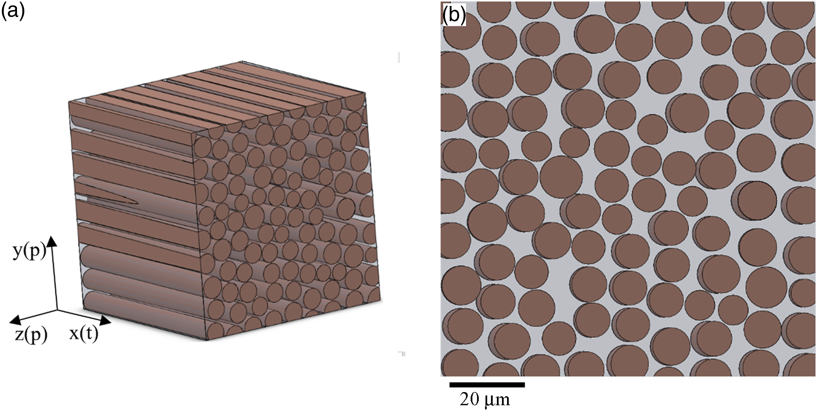
In this study, the experimental approach based on micromechanical testing by instrumented indentation is used to choose the size of the representative volume of the microscopic model of the monolayer. When the indenter is pressed into the polymer composite, both the composite matrix and the fiberglass affect the indentation diagram. At low loads, the indenter penetrates either into the matrix alone or into the fiberglass alone. This leads to a significant spread of indentation diagrams; this spread decreases with a gradual increase in the load and reaches a certain value determined by the spread of the macroscale properties of the specimen, as well as by the measurement error of the device. One of the main properties of the composite under consideration is the normal elastic modulus
The variation coefficient
Figure 5 shows the variation coefficient The effect of the indentation depth on the variation coefficient 
In the statement of the problem of composite monolayer deformation, it is assumed that the fiberglass and the polymer matrix are described by an isotropic elastic medium, whose deformations obey Hooke’s law.43,44 It is assumed that there is a perfect adhesive bond between the matrix and the fiberglass. As a result, the microscale model of the composite monolayer is a cube consisting of glued-together homogeneous regions imitating the structural constituents of the composite, namely the polymer matrix and the fiberglass (see Figure 4). To determine the normal elastic modulus of the composite constituents, the Oliver-Pharr method was applied. This method underlies the ISO 14577 hardness measurement standard.
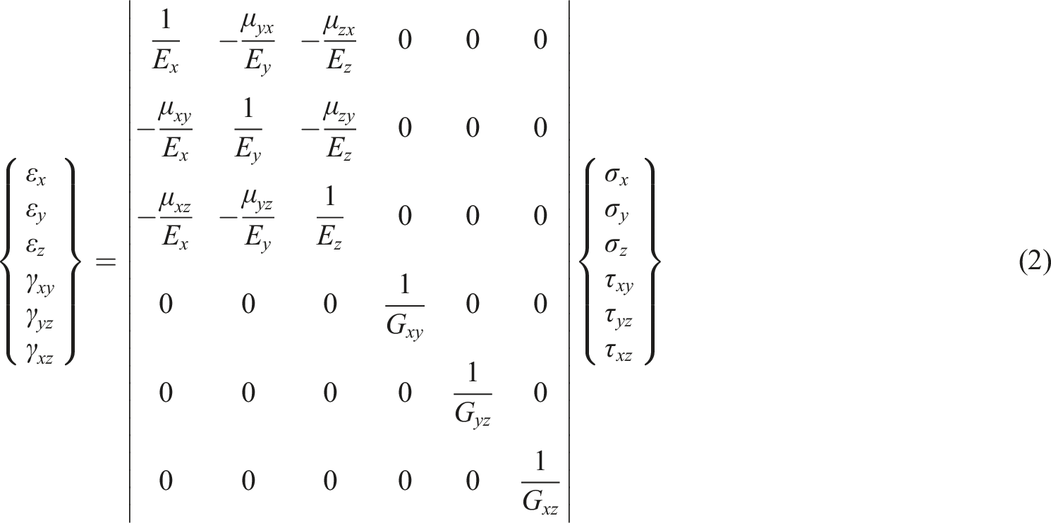
In the statement of the problem of multilayer composite deformation at the macroscale level, it is assumed that the properties of the monolayer are described by a linear elastic orthotropic model.9,45–47 For an orthotropic body, the generalized Hooke’s law can be written as follows 1) for 2) for 3) for Finite element grid (a) and face numbers (b) of the micromechanical model for setting boundary conditions to simulate tension and shear: faces 2, 3, and 4 coincide with the coordinate planes.

Construction of a computational model of fiberglass-reinforced plastic at the macroscale level and the real experimental procedure
In the statement of the tension problem for the cross-reinforced fiberglass plastic at the macroscale level, it is considered that there is a perfect adhesive bond between the adjacent monolayers of the material. 10 layers are used in the finite element model. These layers correspond to 10 monolayers of the fiberglass-reinforced plastic used in the real experiment (see Figure 1). In each layer, the monolayer parameters were specified according to Hooke’s law (2), depending on the location of the fiberglass relative to the tension axis. By analogy with the real experiments, five computational experiments were made with five sets of the parameters in Hooke’s law (2), obtained from the results of micromechanical model calculations. The boundary conditions were set in displacements The numbers of the faces of the macromechanical model for setting the boundary conditions in tension simulation.
Determination of the stress state at the microscale level in the fiberglass-reinforced plastic monolayer at the moment of specimen fracture
In this study, the stress state of fiberglass-reinforced plastic layers at the microscale level at the moment of fracture was determined within the framework of the multilevel approach. For this purpose, from solving the problem of tension of a fiberglass-reinforced plastic specimen, the strain to fracture of the 100×100×100 µm cube was determined during real testing, which corresponded to Setting the boundary conditions for modeling stresses at the microscale level under conditions of the external mechanical loading of the specimen.
Results and discussion
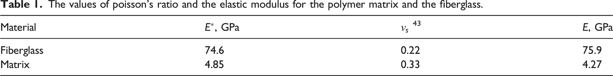
The properties of the constituents of the composite monolayer were determined by the results of the instrumented indentation technique (Construction of a micromechanical model and determination of the elastic modulus at the microscale level). The polymer and the fibers were indented with a Berkovich indenter at loads of 5 and 50 µN, respectively (Figure 9). Table 1 shows the values of the reduced elastic modulus An image of a Berkovich indenter imprint on the fiberglass (a) at a load of 50 µN and the polymer matrix (b) at a load of 5 µN; typical curves of loading by the Berkovich indenter for the fiberglass (c) and the polymer matrix (d). The values of poisson’s ratio and the elastic modulus for the polymer matrix and the fiberglass.
The coefficients of the compliance matrix in law (2), obtained from simulating five micromechanical models.

The simulated results show that the composite has a triple of almost equal paired constants:
As a result, the number of types of experiments for determining the coefficients of the compliance matrix for the fiberglass plastic monolayer can be reduced to three: tension (compression) along the t and p axes and shear in the tp plane (see Figure 4).
Experimental and calculated values of the elastic modulus of the fiberglass-reinforced plastic.

Figure 10 shows the von Mises stress field in the fiberglass-reinforced plastic monolayer with fibers laid along and across the direction of specimen tension. The stress distribution is shown before the moment of fracture of the real experiment specimens under uniaxial tension. In real experiments, the relative elongation of the specimen before brittle fracture is Equivalent von mises stresses before brittle fracture at the macroscale level in the fiberglass-reinforced plastic specimen in the monolayer with glass fibers lying along (a) and across (b) the tensile direction. The fracture pattern of the fiberglass-reinforced plastic specimen during tensile testing at room temperature: the lateral surface of the specimen (a); interlayer fracture (b); fracture of the fibers and the matrix (c, d).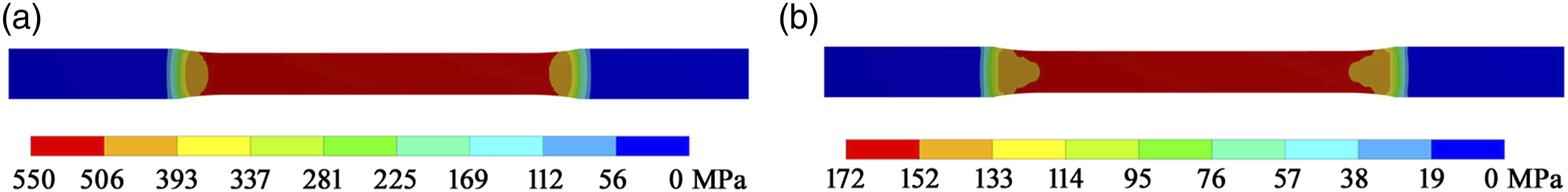

In order to determine the stress state in the structural constituents of the composite at the moment of specimen fracture, the tension of the representative volume of the fiberglass-reinforced plastic monolayer was simulated (see Figure 4) along and across the fiber layout. The applied boundary conditions are given in Determination of the stress state at the microscale level in the fiberglassreinforced plastic monolayer at the moment of specimen fracture, and the calculation results are shown in Figure 12. This figure shows that the maximum von Mises stresses are concentrated in the fiberglass and in the region of the possible location of the interphase zone.49–52 Consequently, these areas have the greatest effect on the conditions of composite fracture and on its elastic constants. Similar conclusions about stress distribution can be made from the results reported in,53,54 which discussed the tension of a representative volume of fiberglass. The interphase zone is not visually observed in an optical microscope. This does not allow the microindenter imprint to be placed in the interphase zone. Most likely, the elastic modulus Equivalent von mises stresses at the micro level in the monolayer tensioned along (a) and across (b) the fiber layout axis at the moment of specimen fracture.
Conclusions
1. A two-level structural hierarchical model of cross-ply fiberglass-reinforced polymer composite has been constructed based on micromechanical tests. The model allows us to simulate the stress-strain state in each monolayer of the composite at the micro and macro levels. 2. Based on the results of simulating the elastic properties of cross-ply reinforced fiberglass, its elastic modulus and Poisson’s ratio have been calculated, which amounted to 31 GPa and 0.11, respectively. The obtained results predict the experimental data with acceptable engineering accuracy, i.e. 27 GPa and 0.10. 3. The results of simulating the stress state at the microscale level in the monolayers of the composite prior to fracture under tensile conditions have shown that the maximum von Mises stresses are concentrated in the glass fiber and in the region of possible location of the interphase zone.
Footnotes
Acknowledgements
The facilities and computing resources of the Supercomputer Center of the IMM UB RAS and the Plastometriya shared access center (IES UB RAS) were used in the study.
Declaration of conflicting interests
The author(s) declared no potential conflicts of interest with respect to the research, authorship, and/or publication of this article.
Funding
The author(s) disclosed receipt of the following financial support for the research, authorship, and/or publication of this article: It was financially supported by the Russian Foundation for Basic Research, project No 19–29-13008.