
Abstract
Synthetic ropes have been used as alternatives for wire ropes owing to their low specific weight and excellent mechanical characteristics. They are essential for offshore mooring in deep water because, at these depths, the weight of steel cables and chains would exceed the forces supported by the platform structure. In addition, they are used in several applications, such as robotics, mountain climbing, fire rescue and lifting loads, sternum closure after medical surgery. They are even used as artificial muscles and active endoscopes because of their high flexibility. These applications are typically characterized by the presence of dynamic loads. Thus, this study aims to experimentally investigate the mechanical behavior of high-modulus polyethylene yarns, supplied by three different manufacturers. The yarns were analyzed after being subjected to impact load and after experiencing fatigue. The interaction between impact load and fatigue was also studied. First, the force, strain, and energy absorbed after the impact load were verified. Subsequently, the influence of the impact load on the fatigue life of the materials was analyzed. Finally, thermal analysis (DSC and TGA) and chemical analysis (FTIR, DRX, and EDS) were performed to compare the materials. It was observed that the mechanical and thermal behaviors of the three materials differed, and there was a reduction in fatigue life, which depended on the impact load due to yarn degradation. Finally, it is concluded that properties such as tensile strength should not be used as the sole parameter for dimensioning polymeric materials, because they exhibit different material properties in several tests despite possessing similar tensile strength.
Keywords
Introduction
Synthetic ropes have been used in climbing for over 120 years. They are an important safety device that is responsible for preventing climbers from falling. This type of rope is usually made of polyamide because they reduce the impact load transmitted to the climber’s body in case of a fall.1–3 Its deformation is mostly elastic, resulting in greater energy dissipation during impact. 3 For their noticeable elastic and cyclic properties, polyamide ropes have also been widely used as mooring lines and hawsers in shallow water and shipping operations.4–8
They are also used in rescue operations, more specifically in firefighters’ activities. These types of ropes have a polyamide core and aramid braided jacket due to its resistance to high temperatures. 9 Polyester ropes are historically used as mooring lines and are also responsible for the sailing controlling system. 1
HMPE (high modulus polyethylene) yarns are currently used in numerous applications, including medical, ballistic protection, offshore mooring/operation lines, sports, cargo lifting and in the robotic field, due to their high strength and low weight, combined with excellent mechanical – for instance, pronounced abrasion and cutting resistance - and chemical properties.10–11 Its fibers are characterized by high strength and high elasticity modulus, producing high stiffness ropes with smaller and lighter diameters, besides its positive flexibility, thus, providing alternative/complementary solutions for traditional polyester mooring lines. HMPE ropes typically have between 2–2.5% strain while polyester has 10–11% at its break. 12
Despite excellent mechanical properties, polymers are highly sensitive to deformation rate, temperature, and to the chemical nature of the environment, 13 being their long-term as well as their elastoviscoplastic behavior full characterization a challenge.14–15
High Modulus Polyethylene (HMPE)
High modulus polyethylene (HMPE) is classified as high-performance fibers. Produced from ultra-high molecular weight polyethylene (UHMWPE), with a molecular mass greater than 106 g/mol, this material is chemically identical to normal high-density polyethylene (HDPE), but its molecular weight is higher.10,12
The UHMWPE has much longer and more flexible molecules. By mechanical processing, these molecules can be forced to assume a longitudinal orientation, providing axial oriented mechanical properties. Presenting weak side bonds (Van der Waals) between the molecular chains, allow transversal resistance and vulnerability to creep become intrinsic characteristics of some grades, although it can be improved, for instance, by the use of a branched base polymer. 10
To manufacture a polymer with improved characteristics, a process called gel-spinning was developed, where UHMWPE molecules are dissolved in a concentrated solvent. In this solution, molecules disentangle and the material is stretched to a very high extent. Based on this, a noticeable high level of macromolecular orientation is achieved, resulting in toughener fiber with high elasticity modulus. The gel-spinning processed fiber is called high modulus polyethylene (HMPE). 10 Gel-spinning fibers, however, usually present a higher cost compared to traditional melt-spinning fibers, which must be taken into account in overall cost–benefit analysis for fiber-based products.
High modulus polyethylene (HMPE) has excellent resistance to abrasion and rupture; high resistance to ultraviolet radiation and high flexibility when compared to other polymeric materials. Material stiffness can be exceptionally high in relation to other fibers, allowing it to be subjected to a higher tension related to the same rope diameter.9,11
Yarn degradation by dynamic loads
Dynamic loads, long-term ones like fatigue or short-term ones like impact, may induce fiber degradation under operation, in correlation or not with chemical reactions. 16 Different types of loads can cause polymer chain rupture at different stages, like solid, molten, or in a solution. The stresses can typically be shear, tension/compression, or a combination thereof. When linear polymeric chains are stretched in the same direction as the applied force, they tend to concentrate the tension mainly in the middle, causing chain splitting. 17
When a polymer is drawn in cold, similarly to an impact load, the chains are aligned in the direction of the stretch. Bonds near the ends of the polymeric chain are much less likely to be broken during mechanical degradation than bonds closer to the center of the chain. 16
Three types of yarn failure mechanisms due to fatigue can be highlighted: creep, external friction and internal friction. The most common fatigue failure is related to creep. If the failure is controlled by fluency and no other mechanism interferes, failure time may be test frequency independent, depending only on the time spent under load.18–20 Thus, models can be used to predict deformation under static load, replacing the constant load for a cyclic one.18–19 For fiber-based products, however, rope design plays a major role regarding rope lifespan under cyclic loading, considering, for instance, aspects related to fiber friction under proposed design. 6 So, friction phenomena between fibers can add to deviations in creep-based fatigue life and frequency must then be taken into account. 19
Unlike metals, where fatigue is characterized by a crack propagation, this phenomenon has different characteristics when related to polymeric materials. In such case, the wear sensitivity is increased by factors such as modulus, rate, load amplitude frequency, temperature, relative humidity and environmental pH, 21 besides fiber conditioning (wet x dry) during the test or operation.
Fatigue failure with small loads and high cycles in polyester and nylon ropes usually occurs due to internal and external fibers friction. In addition, after a certain load amplitude, the ropes may start to rupture due to plastic deformation. 19
In synthetic HMPE ropes, it has already been observed that the greater the tensile amplitude, the smaller is the number of cycles to rupture. In addition, residual stress is found after cyclic load. 23 Fatigue life of the HMPE is directly affected by ambient temperature. As the temperature increases, the number of cycles until rupture decreases, and the failure is induced by abrasion, thereby dictated by the number of cycles, with no influence of frequency. 21 Comparing the most used fibers in ropes, HMPE and aramid show greater tensile strength and fatigue life than others for the same specific mass, 24 being aramid, however, proven particularly sensitive to compression cyclic loads.
When fibers are subjected to a sudden shear prior to a tensile load, a rearrangement of molecules occurs in the rope. At a product scale, an increase in tensile causes an increase in the stiffness of the fibers due to the decreasing angles in relation to the rope axis for different designs. 25 Consecutive impact loads are proven to potentially increase the stiffness of synthetic material ropes,3,11 becoming stable with increasing impacts.11,26 When a preload is applied to the ropes, they may present different responses. As an example, HMPE has a greater stiffness than aramid after preload, using the yarn breaking load as reference. 27
In polyester yarns, it has been observed a reduction in fatigue life after an impact load that depends on its magnitude. 28 In addition, for tensile tests after lower loading impact conditions, synthetic fibers show strength increase. However, as the impact load is increased, the mechanical strength decrease. 29 This can occur due to fibers rupture during the impact at high loads, which must be of attention depending on application.
Another important factor is the impact load study where the ropes are directly connected to the human body, such as fire and climbing ropes. Depending on the energy rate absorption, the values of dynamic loads can exceed the human body limit resulting in bone fracture or even death. It was observed that more stiffness ropes have higher dynamic loads values. 9
A decrease in fiber impact resistance can be observed due to material physical conditioning and/or material degradation. For instance, polyamide fibers tend to have lower impact resistance under wet conditions. 30 This phenomenon can be caused by an increased in the frictional load between the fibers, caused by water absorption. In addition, the photo-oxidative degradation of susceptible fibers may alter the chemical structure of their molecules and consequently decreases the energy rate absorption and the materials elasticity. 1
In order to contribute to the research of related synthetic materials, the present work evaluated the mechanical behavior of three types of HMPE (high modulus polyethylene) yarns from different manufacturers through experimental tensile, fatigue, impact, creep, quasi-static and dynamic stiffness tests. A brief chemical characterization of the materials was carried out by means of X-ray diffraction tests (DRX), scanning electron microscope (SEM) and infrared spectroscopy with Fourier transform (FTIR). Finally, thermal analysis was performed using DSC (differential exploratory calorimetry) and TGA (thermogravimetric analysis) for further comparison of fibers.
Materials and methods
Specimen
The material used was HMPE (high modulus polyethylene) produced by three different manufacturers, codified herein as HMPE #1, HMPE #2 and HMPE #3. A rope design consists on a braided jacket and a core. The core may be formed by sub ropes, which are formed by strands. The strands are made up of yarns in a scale-up approach. For most constructions, the core is responsible for most of the mechanical properties of the rope while the braided jacket would have a primarily protection role, preventing a core environmental mechanical damage and/or abrasion. For other hawser constructions, the cover may also play a mechanical role on overall rope performance, contributing to its strength as proposed by OCIMF (Oil Companies International Marine Forum) guidelines.
In the present work, yarns were used as they represent the basic unit for rope design. Specimens were prepared with a length of 500 mm (as proposed alternatively by ASTM D 885) with tabs on the ends (for improved gripping). Tests were performed in a controlled environment with temperature and relative humidity of 20 ± 2°C and 65 ± 4°C respectively, to which samples were previously exposed for 2 h prior to testing. 31
Material characterization
Yarn breaking load for fibers characterization was obtained through tensile testing according to ASTM D 885 on a machine model INSTRON 3365. A displacement control at a rate of 250 mm/min was adopted 32 for an amount of 30 samples per material, totalizing 90 samples.
After initial characterization, drop-weight impact tests were performed defining an output of failure/not failure from a 300 mm height with a 1% YBL increment to achieve the YBL percentage that provokes rupture in a single drop. For this test, a drop-weight test tower was developed as shown in Figure 1. Drop-weight test tower: (a) load cell, (b) terminals, (c) deformation marker, (d) weight and (e) specimen.
To measure the impact load over time in the samples a ±10 kN load cell. Mounted at the upper end of the equipment with the data acquisition frequency of 5 kHz. 33 The elastic deformation and the absorbed energy are calculated using the ENA methodology.3,26,34
Loading ranges analyzed.

Then, quasi-static and dynamic stiffness tests were performed. As a reference value, the average of three tested samples of each material was used. 30 Test parameters follow the ABNT ISO/TS 14,909:2013 standard. 36 The first section is the Quasi Static: (i) A ramp to 10% YBL in a minute; (ii). 10% YBL for a minute; (iii). A ramp to 30% YBL in 2 min; (iv). 30% YBL for 30 min; (v). A ramp to 10% YBL in 2 min; (vi). 10% YBL for 30 min. The process is repeated three times, to achieve the Quasi-Static data. The second is the dynamic section, with a frequency of 0.1 Hz, 100 cycles at a load between 30% YBL and 40% are applied, then another 100 cycles between 40 and 50% YBL and in the end 100 cycles between 50 and 60% . 36 Finally, creep tests were also performed on an EMIC DL-2000 machine according to ASTM D 885 at loads of 70%, 80% and 90% YBL, through a displacement rate of 450 mm/min. 32
A scanning electron microscope (SEM) model JSM - 6610LV was used to analyze the samples before and after impact at 4 and 5% YBL as well as samples broken by fatigue. Moreover, a spectroscopy in the infrared region (FTIR) analysis was performed to identify the functional groups present in the materials for confirmation purposes.
The samples were submitted to spectroscopic determination in the infrared region (450-4500 cm-1). Using a machine model PRESTIGE 21, 210,045, and the technique of total attenuated reflectance (ATR-FTIR). Finally, an X-ray diffractometer (XRD) model D8 ADVANCE/ DAVINCI was used in the original samples and after impact with 4% and 5% YBL. The diffraction angle varied from 5° to 75° in 0.05 nm intervals. 37
Thermal analysis was performed by differential scanning calorimetry (DSC) analysis and thermogravimetric (TGA) analysis or comparison purposes between fibers. DSC analysis was performed using a Shimadzu DSC – 60 calorimeters, from 25 to 300°C temperature range, at 10°C min−1 heating rate according to ASTM D 3418. 38 Thermogravimetric results (TGA) were obtained on a Shimadzu TGA-60 thermobalance model with a 10°C min−1 heating rate. The samples were placed in aluminum pans and heated from 35 to 550°C in inert atmosphere according to ASTM E 1131. 39
ANOVA analysis was performed to investigate the influence of the effects (main and interaction) of the input factors: (i) material, and (ii) exposure to a previous impact load on the fatigue response of the materials in each interval. A significance level α=0.01 was adopted.40–41 IBM SPSS Statistic 22 commercial software was used.
Results and discussions
Yarn breaking load (YBL)
Yarn breaking load results (ASTM D855).

YBL was found to be similar for the three materials with a smaller scatter for HMPE 3. It can be observed that HMPE 2 has the highest tensile strength, approximately 6% higher than the other two materials. However, the strain values of all three are similar.
Impact load
The post-impact material behavior was analyzed in two phases: (i) verification of load value leading to yarn rupture by experimenting with a free fall weight from a height of 300 mm, and (ii) analysis of the transmitted load versus time. In addition, it was determined that the physical parameters of the yarns post impact (maximum deformation, viscoplastic part of yarn deformation, elastic part of yarn deformation, and stored anergy).
Failed samples out of 20 impact tests for each reference load.
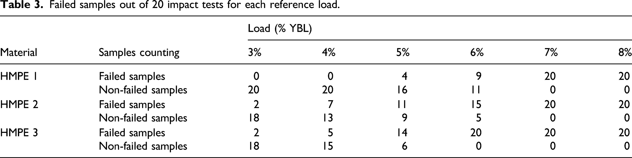
However, the 6% YBL for HMPE one and HMPE 2 (approximately 3.1 kg and 3.3 kg, respectively) and the 5% YBL for HMPE 3 (approximately 2.6 kg), should be considered as critical values because, at these reference loads, more than 50% of the samples failed under impact. Figure 2 (a) presents the impact rupture load versus time curves. On average, 30 samples were used to plot the curve. Impact load curves. (a) Impact rupture load. (b) Impact load - 4% and 5%YBL.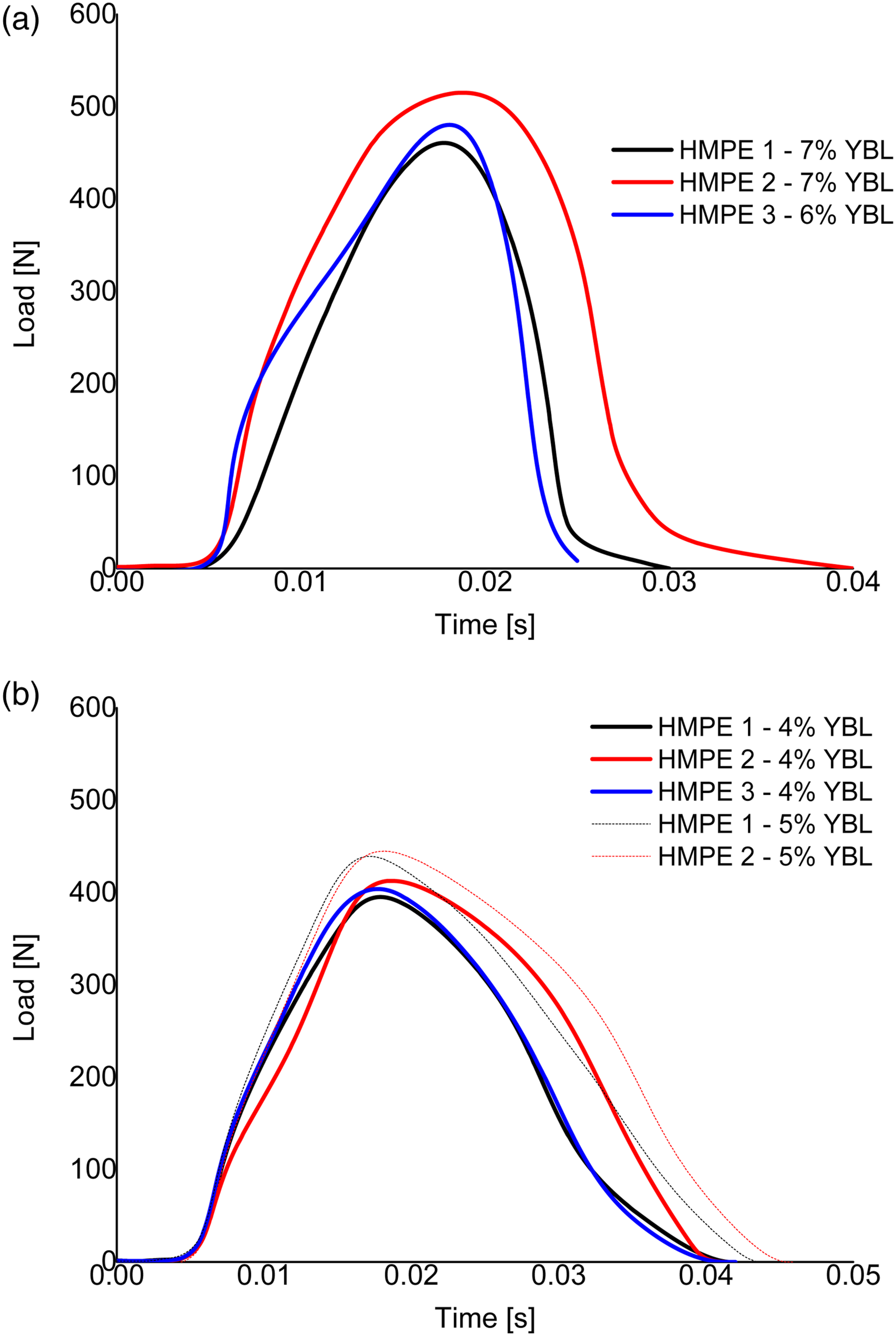
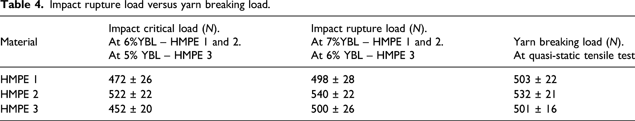
Impact rupture load versus yarn breaking load.
Considering the aforementioned results, loads of 4% and 5% YBL were selected for impact loading prior to the fatigue evaluation. Figure 2 (b) presents the force versus time curves for a free fall of 4% and 5% YBL. The HMPE three curve was not presented because a mass of 5% YBL was already sufficient to induce rupture in approximately 70% of the specimens. On average, 30 samples were used to plot the curve.
Figure 3 presents the maximum elastic and viscoplastic deformations measured using a scale in the impact tests and the energy stored during the application of the impact load.26,34 It must be noted here that the impact tests for were conducted for the same duration for each material since it was conducted in the form of the free weight drop. Physical parameters - 4% and 5% YBL. Structural analysis of yarns.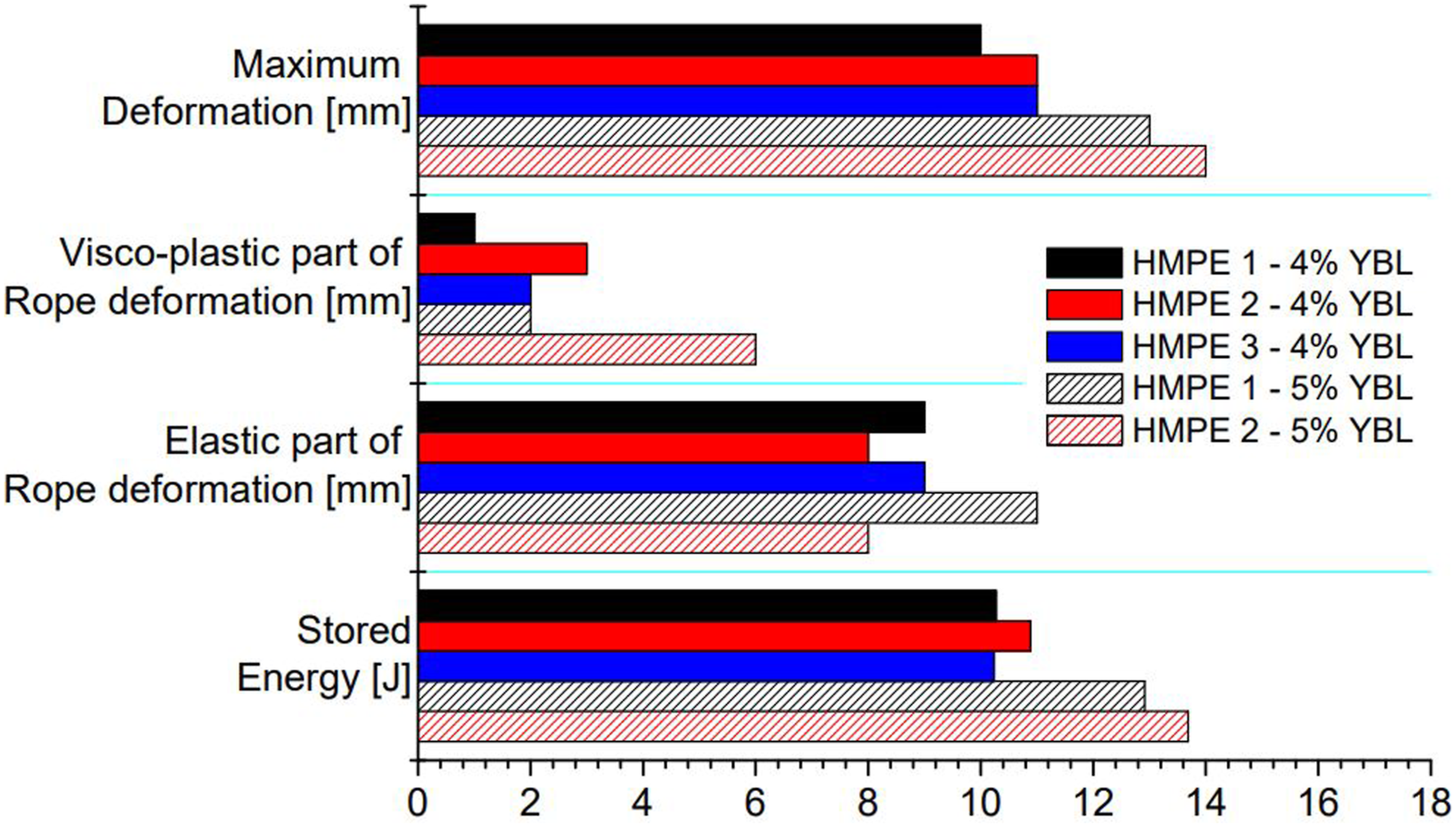
HMPE two stored a marginally greater amount of energy during the application of impact load. This can be attributed to the fact that it experienced the largest mass drop, which was expected considering that the stored energy in the yarns is directly proportional to the mass and the maximum deformation. 34
For the 5% YBL impact load, HMPE one exhibited a slightly lower total deformation compared to HMPE two and three. By analyzing the elastic deformation, it can be observed that HMPE two exhibited slightly lower deformations than HMPE one and HMPE three. This is an important parameter because it is responsible for driving the mass in the opposite vertical direction, causing an undesirable acceleration.
Diameters.

Table 5 shows that the HMPE three yarns exhibit the greatest degradation after 4% YBL impact load. However, SEM analysis fails to clarify the cause of degradation. There are two possible causes: (i) the elongation of the yarn during impact which results in reduction of the filament diameter to conserve volume or (ii) the division of the yarns.
Fatigue
Figure 4 presents a boxplot of the three materials. The y-axis shows the number of cycles up to rupture, and the x-axis represents the load amplitude. The material conditions adopted for the fatigue analysis are presented in different colors. Number of cycles versus amplitude.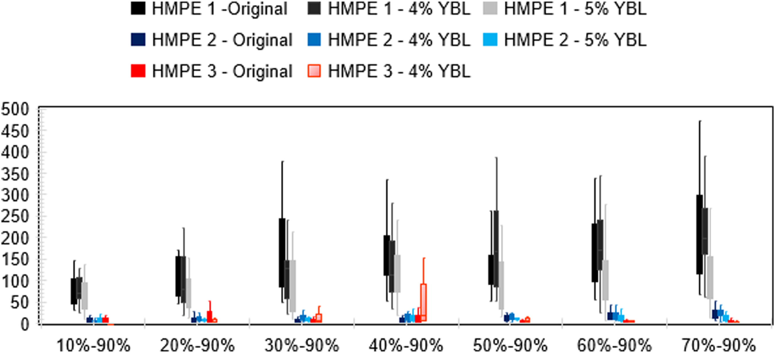
It can be observed that the fatigue life of the original HMPE one and HMPE two increased as the load amplitude decreased. The boxplot analysis demonstrated that the fatigue life of HMPE one and HMPE two did not vary significantly at 4% YBL impact load, and that HMPE one performed considerably better. However, after the application of 5% YBL impact load, both materials exhibited a reduction in the number of cycles.
For HMPE 1 and 2, the fatigue life dependency on the load amplitude is clear for the original 4% YBL impact load sample. However, after the 5% YBL previous impact load, this dependency is no longer evident, owing to the overall reduction of fatigue cycles up to rupture.
HMPE three exhibited completely different behavior. Not only was the number of cycles up to rupture for the original material significantly smaller than that for HMPE 1, but the relation between the fatigue resistance and the decrease in the load amplitude was also not pronounced as in the other materials.
By analyzing the HMPE three box plot, it is possible to infer that the fatigue life tends to increase after 4% YBL impact load for an amplitude of 40–90% YBL. In contrast, for an amplitude of 10–90% YBL, fatigue life decreased significantly post impact. Fatigue life varied also at the other amplitudes. Therefore, to obtain more precise results, an analysis of variance was conducted.
Figure 5 presents the S-N curves for amplitude versus the logarithm of the average number of cycles until rupture. Fatigue S-N curves - (a) HMPE 1, (b) HMPE two and (c) HMPE 3.
Figure 5 shows that the original yarns of HMPE one and HMPE two exhibit an increase in fatigue life when load amplitude decreases. In contrast, HMPE three presents random data and behaves differently from the others. The tendency curves are not presented because the random results do not represent the facts obtained.
Analysis of variance (ANOVA) was conducted for each load amplitude (10–90% YBL to 70–90% YBL) to investigate the effect of the impact load on the material. However, the analysis of variance directly comparing the three materials did not satisfy the criterion of sample equality. Therefore, it was necessary to compare only HMPE one and HMPE 2, considering the original samples and the two levels of impact load (4 and 5% YBL impact load).
Analysis of variance (ANOVA).

Quasi-static stiffness, dynamic stiffness and creep
Figure 6 presents the evolution of the quasi-static and dynamic stiffness of the three HMPE yarns.
36
Evolution of QSS and DS.
Figure 6 shows that HMPE one exhibited a higher stiffness than HMPE two and HMPE 3. Despite this, similar results were obtained in the material mechanical behavior stiffness tests. The first evaluated quasi-static stiffness (QSS #1) was lower than for all three materials. At the measurement (QSS #2), a significant increase in stiffness was observed. Finally, in the third measurement (QSS #3) the increase in stiffness was reduced to a range where the trend and rigidity remained constant.
In terms of dynamic stiffness, HMPE one exhibited the highest stiffness. The first dynamic stiffness evaluated (DSS #1) was lower than 14 for all three materials. Similar to QSS #2, DSS #2 showed a significant increase. Finally, in the third measurement (DSS #3), each material exhibited a different behavior. HMPE one continued to exhibit a significant increase in stiffness; HMPE two exhibited a smaller increase in stiffness; and HMPE three exhibited a slight decrease in stiffness from DSS #2 to DSS #3 but did not fall to the initial low value.
Figure 7 shows the average of the results obtained in the creep tests for the 70, 80, and 90% YBL loads of the three HMPE yarns. It must be noted that the time scale was reduced during the load increase, thereby making it necessary to present the creep curves separately. Creep – (a) 70% YBL, (b) 80% YBL and (c) 90% de YBL.
The creep curves clearly present the differences between the materials. HMPE one obtained the best results in the creep tests, whereas HMPE three obtained the worst. In general, these results show that the creep rate decreases with time in the primary stage, and then stabilizes to a constant rate in the secondary stage. The lifetime, which is the time required for a sample to break, decreases with the increase in loading levels.
It can be inferred from the instantaneous deformation observed in the creep curves that HMPE three suffered the highest deformation, confirming the results of the tensile tests. However, HMPE three exhibited unexpected behavior in the 80% YBL creep test, as shown in the creep curve. This can be attributed to the nonuniformity of the material, resulting in dispersion and low structural reliability.
Material characterization
Figure 8 (a) presents the X-ray diffraction results. It was possible to identify the crystalline regions of the three materials based on the appearance of narrow and intense peaks. The degree of crystallinity of the samples was determined using equation (1).
42
(a) X-ray diffraction (XRD) analysis result; (b) Infrared Spectrum – FTIR (Fourier Transform Infrared Spectroscopy).

The degree of crystallinity
Figure 8 (a) shows that the diffraction crystalline peaks of the three materials are found in similar positions, i.e. 2θ= 21.52° and 24.09°, indicating similar crystalline structures. In addition, the diffractogram enabled the determination of the degrees of crystallinity for each material. HMPE one exhibited the highest crystallinity at 60.61%, followed by HMPE 2 with 54.39% and finally, HMPE 3 with 36.50%. This difference in crystallinity can be considered as the cause of differing mechanical behavior of the materials since crystallinity affects the mechanical properties of polymers. 43
The spectra of the three materials showed similar absorption bands in the infrared region, as shown in Figure 8 (b): The bands at 2924 and 2851 cm−1 correspond to the asymmetric and symmetric CH2 stretches, respectively. Those at 1462 and 1365 cm−1 correspond to the scissor-like angular deformation of CH2 and CH3 groups, respectively and finally, the 720 cm−1 band is related to the out-of-plane deformation of the CH2 group. 44
Figure 9 shows the thermogravimetric (TGA) and differential exploratory calorimetry (DSC) curves. The tests were conducted in an inert atmosphere for the three materials: HMPE 1, HMPE 2, and HMPE 3. Thermogravimetric (TGA) and differential scanning calorimetry (DSC) curves.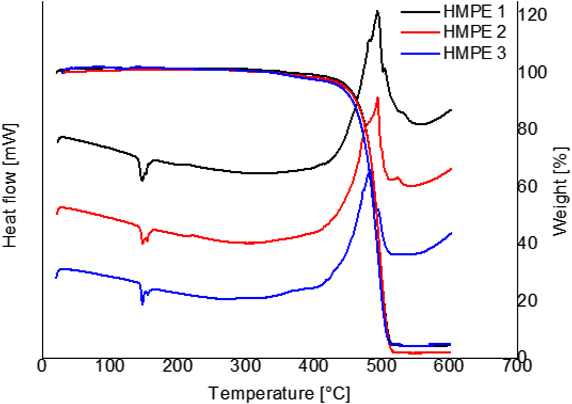
As shown in Figure 9, the thermogravimetric curves (TGA) demonstrated that all the three materials retained residual mass after the thermal degradation of the polymer (above 500°C). HMPE one exhibited a smaller residual mass (approximately 1% of initial mass) compared to the other two materials (approximately 4.5% of the initial mass). In addition, the TGA curves show that the degradation of organic matter at lower temperatures can be verified in the case of HMPE 3.
The differential scanning calorimetry (DSC) curves showed endothermic peaks in the temperature range of 150°C, indicating melting. Here, the energy of the system reduces the secondary intermolecular loads between the crystalline phase chains. Changing from the rubbery state to the viscous (fluid) state. In addition, exothermic peaks at 500°C, indicating the degradation of the polymer chain, were observed. This behavior was also observed in the mass loss shown in the TGA curves.
Therefore, we can conclude that HMPE one also differs thermally. This is because degradation occurs later in HMPE two and HMPE 3, which do not exhibit any significant differences in behavior.
Conclusions
In this study, three HMPE yarns from different manufacturers were studied considering their cyclic performance after several impact loads. First, tests were performed to analyze the dynamic behavior of the yarn materials. Subsequently, mechanical, chemical, and thermal characterizations were conducted with the objective of corroborating the results obtained in the dynamic tests.
The YBL for the three groups of materials was greater than 500 N. HMPE one exhibited the least elongation at rupture with 14 mm. HMPE two and three stretched to a length of approximately 16 mm. It can be observed that HMPE 2 has the highest tensile strength, approximately 6% higher than the other two, despite similar strain values. These YBL results have previously been validated by other researchers, who have established that HMPE has a high linear tenacity [N/tex] compared to other fibers. For example, HMPE yarns have a linear tenacity [N/tex] four and 1.5 times greater than that of polyester yarns and Aramid yarns, respectively.14,45
Rupture of the samples was achieved by using them to drop a weight from a height of 300 mm, for which all three groups of materials were tested for the same duration. The results showed that rupture occurred at 3.6 kg (7%YBL) for HMPE 1, 3.8 kg for HMPE 2 (7%YBL) and approximately 3.1 kg (6% YBL) for HMPE three at loads of 498 N, 540 N and 500 N respectively, similar to the quasi-static tensile break loads. However, these tests are not conclusive Since a majority of the samples ruptured at smaller loads. For instance, HMPE three exhibited a critical impact load of 10% less than its YBL.
Moreover, the mechanical behavior of the impacted materials showed that HMPE two had the highest impact resistance, as can be observed in the stored energy graphics. The HMPE two material stored a slightly greater amount of energy during impact load, which can be attributed to it receiving the largest mass drop in the impact test. Considering that stored energy in the yarns is directly proportional to the mass and maximum deformation , 34 this was an expected result.
Furthermore, in the impact load to rupture tests, HMPE one showed greater resistance to consecutive impact. Thus, it is not possible to conclude which material is more resistant to impact because successive impact loads affect the behavior of the material.
In addition, the yarn structure was analyzed. Considering 4% and 5% YBL, it was observed that HMPE three exhibited the greatest degree of degradation before rupturing. The diameters were reduced owing to the yarn elongation, indicating the structural behavior represented by Poisson’s ratio. 13
Another important parameter that was tested was the fatigue resistance. According to the tests, this is primarily influenced by the intrinsic properties of the material itself. Both the original and post-impact samples of HMPE one exhibited excellent resistance at all amplitudes; HMPE two and HMPE three generally showed similar resistances. However, after impact with 4% YBL, only HMPE three presented a variation in fatigue life. Similarly, HMPE one and HMPE two exhibited decreased fatigue life after impact with 5% YBL. It must also be noted that the tests on HMPE three resulted in a large amount of random data, in contrast to the other two materials.
The quasi-static and dynamic stiffness tests resulted in similar curves, which showed a tendency to stabilize. The first measured stiffness (QSS#1 and DS#1) was the lowest for all the materials, followed by a considerable increase when measured for the second time #2 (QSS#2 and DS#2), and finally, a smaller increase in terms of the quasi-static stiffness at the third measurement.
In these stiffness tests, HMPE one performed best in contrast to HMPE 3, which performed worst, corroborating the findings of the previous tests. This confirmation was possible primarily because the tests evaluated both the static and dynamic behaviors of the material. It is important to note that a distinct QSS and DS drop was observed after several repetitions of the test cycle, indicating that stiffness diminishes with time. This represents a significant problem in terms of design and application.
HMPE three exhibited the highest instant deformation, as shown by the creep curves, despite tensile tests results to the others. Furthermore, the creep test results of HMPE three were unexpected, as shown by the 80% creep curve. This can be attributed to the nonuniformity of the material. For all three materials, a greater load value, resulted in lesser elongation until rupture. In addition, HMPE one exhibited the highest creep resistance, which is interesting considering that the YBL results were similar for all three materials. However, discrepancies were found in the fatigue test results, with HMPE one exhibiting higher resistance.
XRD analysis demonstrated that the materials possessed different crystallinities, with HMPE one exhibiting a crystallinity approximately four and 1.5 times higher than HMPE 3and HMPE 2, respectively. The difference in mechanical behavior between the materials can be attributed to this difference in crystallinity, which, was observable in the fatigue and creep tests but not the tensile tests.
In addition, the thermal characteristics were analyzed using TGA and DSC. which showed that HMPE one differed in its thermal behavior since its degradation begins later compared to the others.
Therefore, it is concluded that fatigue life decreases depending on the impact load. This is because yarn degradation causes the material to lose resistance. However, in the absence of load-induced yarn degradation, the resistance might increase due to the plastic orientation of the molecules caused by the shear stress induced by the applied load.
HMPE has a high resistance compared to other fibers owing to its high level of orientation. HMPE 3 has the lowest orientation among the studied materials, which explains the increase in fatigue life at certain amplitudes in the post-impact samples of HMPE 3.
Finally, it is concluded that parameters such as tensile strength should not be used as the sole point of reference for dimensioning in projects. This is because polymeric materials perform differently in several tests, despite having a similar tensile strength.
Footnotes
Declaration of conflicting interests
The author(s) declared no potential conflicts of interest with respect to the research, authorship, and/or publication of this article.
Funding
The author disclosed receipt of the following financial support for the research, authorship, and/or publication of this article: This work was supported by the Coordenação de Aperfeiçoamento de Pessoal de Nível Superior (88882.444114/2019-01).