
Abstract
Nanoclay added cyanate ester resin (Type I) composites were fabricated by adding different weight percentages (0,1,2,4 & 6 wt%) of organo-modified Montmorillonite (o-MMT) and tested for dispersion by Small angle X-ray scattering(SAXS), thermal stability using Thermogravimetric analyser (TGA) and curing behavior using Differential scanning calorimeter (DSC). This data was correlated with the thermomechanical properties of nanoclay added carbon fiber reinforced cyanate ester resin composites (C-CE composites /Type II). Interlaminar shear strength (ILSS), flexural strength of type II composites increased by about17%, 21% respectively at 2 wt% addition of nanoclay although at this loading nanoclay was found to show intercalation.Thermal stability of type II composites got reduced whereas the ablation rate has increased for type II composites with increased loading of nanoclay. However, percentage increase in ablation rate was found to be lower when type II composites were tested at 5000 kWm−2as compared to the ablation testing carried out at 1250 kWm−2. Scanning electron microscopy studies indicates significant melting of nanoclay at high flux resulting in additional protection mechanisms for the composites at high flux. Present study indicates the possibility of using o-MMT nanoclay for improved mechanical properties of C-CE composites used in thermal protection systems (TPS).
Keywords
Introduction
Phenolic resin based ablative composites are more popular in aerospace applications due to its low cost, ease of availability raw materials. 1 However, phenolic resin suffers from low shelf life and out life due to easy crosslinking of methylol groups present in the aromatic structure leading to variation in properties of the resultant components as function of storage life. One of the alternate choice as ablative matrix is cyanate ester (CE) resin, which is an addition cured thermoset polymer synthesized by the reaction of phenolic resin with cyanogen bromide. 2
It was reported that, the CE resin has higher decomposition temperature and char yield than phenolic resins.3,4 Moreover CE undergoes addition curing without releasing any gaseous by products which enables easy processing. 5 However, there is limited literature available on the processing, properties of the fiber reinforced cyanate ester resins for ablative applications.
On the other hand, researchers have explored addition of various nano materials like nanosilica, carbon nanotube, nanoclay, polyhedral oligomer silsesquioxane, nanozirconium tungstate to neat cyanate ester resin for enhancing their thermomechanical performance.6-8 Among all these fillers, organic treated nanoclay is more popular due to its low cost and compatibility with the organic resin systems. Improvements in strength and stiffness for the polymeric systems with the addition of a small amount of nanoclay particles was reported earlier. 9 This is mainly attributed to the higher modulus and surface area of nanoclay. 10 In general it is believed that, the exfoliation of nanoclay is essential to get improved thermo mechanical properties for the composites. 11 However, intercalated nanoclay platelets also should contribute as fillers in improving the properties of the composites by virtue of their high surface area, good bonding with the matrix. So far no systematic studies were carried out on this aspect. It is reported that the nanoclay as filler imparts improved thermal stability and reduced thermal conductivity for host composites which are intended attributes for TPS applications. 12 For instance, Bershtein et al. prepared amino functionalised nanoclay–cyanate resin composite with different clay loadings and reported that ultra-low nanoclay content (0.025 to 0.1 wt. %) improves modulus, thermal stability and creep resistance of cyanate ester resin. 13 Various researchers have reported that the nanoclay has shown positive effect on cure kinetics, glass transition temperature, crack resistance, flame resistance for host matrices.14-17 Thus nanoclay has become a preferred nano filler to improve the performance of C-CE based TPS.
Limited research work was reported in the area of nanoclay added C-CE composites. Doherty et al. prepared carbon fiber/cyanate ester resin composite with high temperature organo modified nanoclay and reported that the nanoclay improved thermal stability of resin, marginally improved short beam shear strength and decreased open hole compression strength. 18
Nanoclay is known to form glassy phase at high heat flux as compared to low heat flux. 19 Thus its performance as an ablation inhibitor may be higher at high heat flux. So far there are no studies reported on the effect of heat flux on the ablation performance of the nanoclay added polymer matrix composites. In this paper, it is aimed to address this gap.
Therefore, the objectives of the current work are preparation of carbon fiber-cyanate ester resin composites reinforced with different weight percentages addition of o-MMT nanoclay and understanding the thermomechanical behavior of the resultant composites, to study the effect of heat flux on ablation rate and to find out optimum percentage of nanoclay for TPS applications.
Materials
Novolac phenolic based cyanate ester resin (PT 30 S) was procured fromM/s Lonza Pvt Ltd.Cyanate ester resin has solid resin content of about 75 wt % and methyl ethyl ketone solvent content of about 25 wt%. PAN based Carbon fabric (Torayca Carbon Fiber T 300, 3 K) was used as the primary reinforcement because of its good mechanical properties. Nanoclay used in this study (Nanomer 1.31 PS, M/s Sigma-Aldrich) was surface-modified Montmorillonite (o-MMT) with 0.5–5 wt% aminopropyl triethoxysilane, 15–35 wt % octadecyl amine.
Experimental work
Dispersion of o-MMT nanoclay in cyanate ester resin
Approximately 200 g, cyanate ester resin was taken in to a 500 ml stainless steel (SS) bowl. Required quantity of o-MMT nanoclay was added to the resin at room temperature.This mixture was initially stirred with a glass rod for approximately 5 min. Then this mixture along with the bowl was placed in to a planetary ball mill (M/s Insmart Systems) and ball milled for 2 h at 250 rpm using SS balls. Ball to charge ratio was maintained at 0.5:1. Thus four different types of o-MMT nanoclay CE resin compositions were prepared by adding 1%, 2%, 4% and 6 wt% of nanoclay to CE resin. Viscosity changes of the resin due to the nanoclay addition were measured using Brookfield viscometer at 30°C.
Preparation of type I composites
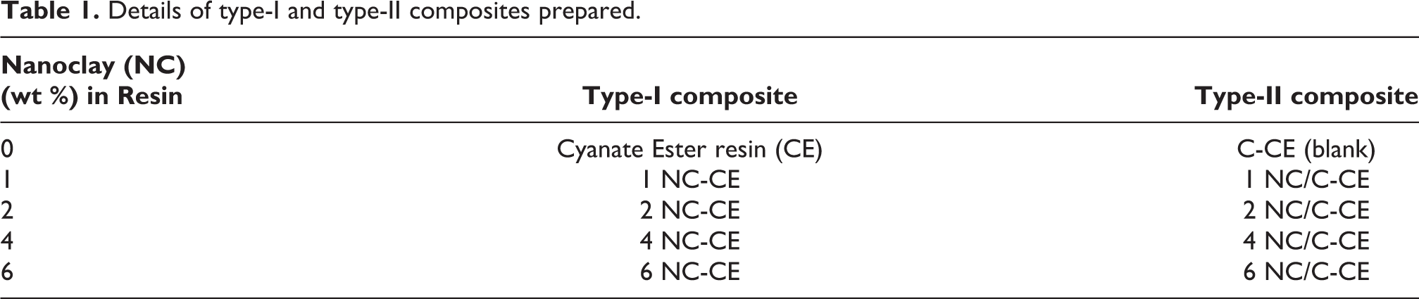
Nanoclay added cyanate resin was poured into a petri dish and the volatiles were allowed to evaporate by heating the mixture to 60°C for1 h. Subsequently nanoclay resin was cured in a hot air oven by heating resin to 120°C for 1 h, 150°C for 1 h and 177°C for 3 h and then cooled to room temperature.This was post cured at 100°C for 30 min, 150°C for 30 min, 200°C for 30 min and 250°C for 3 h. Post curing was carried out to obtain complete polymerisation. Thus, four different variants of type I composites were made along with the blank cyanate ester resin matrix sample. Details of the prepared type I composites are given in Table 1.
Details of type-I and type-II composites prepared.
Preparation of type II composites
Carbon fabric (thickness 0.38 mm) layers having a size of 300x300 mm were cut and impregnated with nanoclay dispersed cyanate ester resin. Twelve such layers were stacked on a flat metal plate by hand lay-up process. These stacked layers were subjected to vacuum bagging, followed by curing in the autoclave. Curing was carried at 120°C for 1 h, 150°C for 1 h, 177°C for 3 h under a pressure of five bar and vacuum of one bar and then cooled to room temperature. Cured composites were again post cured to get complete polymerization as per post cure cycle mentioned for type I composites. Thus five different variants of the type II composites were prepared along with the blank C-CE composite. Details of the prepared type IIcomposites are given in Table 1.
Characterisation and testing
Curing behaviour of type I composites
Differential scanning calorimetry (DSC: M/s TA instruments, Q200) was used to monitor the curing reaction of the neat resin and type I composites. DSC runs were carried out from30 to 400°C with a sample mass of 10 ± 2 mgat a heating rate of 10°C/min under nitrogen flow of 50 mL/min.
Dispersion studies of nanoclay in resin
Type I composites were evaluated for the dispersion of the nanoclay in resin using small angle X-ray scattering (SAXS: Antonpaar, Model: SAXS Point 2.0) by scanning the samples from 1° to 10°. Dispersion is also evaluated using Scanning electron microscope (SEM) (Table Top SEM, Make: SEC, Korea, Model: SN4500 Plus). Prior to SEM studies, surface of the samples was coated with a thin gold film with a sputtering unit (Make: M/s Hind HiVacuum India, Model: Scancoat Six).
Density, fiber volume fraction (%Vf)
Density and fiber volume fraction of type II composites were determined as per ASTM D792 & ASTM D 3171 respectively.
Thermal stability test
Thermal stability of as received nanoclay, type I and type II composites in nitrogen atmosphere were evaluated using TGA upto 900°C at a heating rate of 10°C/min.Weight of the carbonaceous char (CR) and temperature at which 5% weight loss (T
Interlaminar shear strength (ILSS) & flexural strength
ILSS and flexural strength tests for type II composites were carried as per ASTM D 2344, ASTM D 790 respectively using UTM (M/s ADMET, Model 2505).
Oxyacetylene flame test
Oxyacetylene flame test was carried out as per ASTM E285 for type II composites by collecting samples having size of 100 ± 1 mm × 100 ± 1 mm x 4.2 ± 0.1 mm. One set of samples of type II samples were subjected to the heat flux of 5000 kWm−2 for period of 60 s, whereas the other set of samples were subjected to the heat flux of 1250 kWm−2 for a period of 60 s. Mass ablation rate for these samples were calculated as mass loss per second. Two samples were tested at each flux and the average ablation rate was reported.
Characterisation
Samples exposed to Oxyacetylene flame were tested for the changes in the microstructure using SEM.
Results and discussions
Effect of nanoclay content on curing behaviour of cyanate ester resin
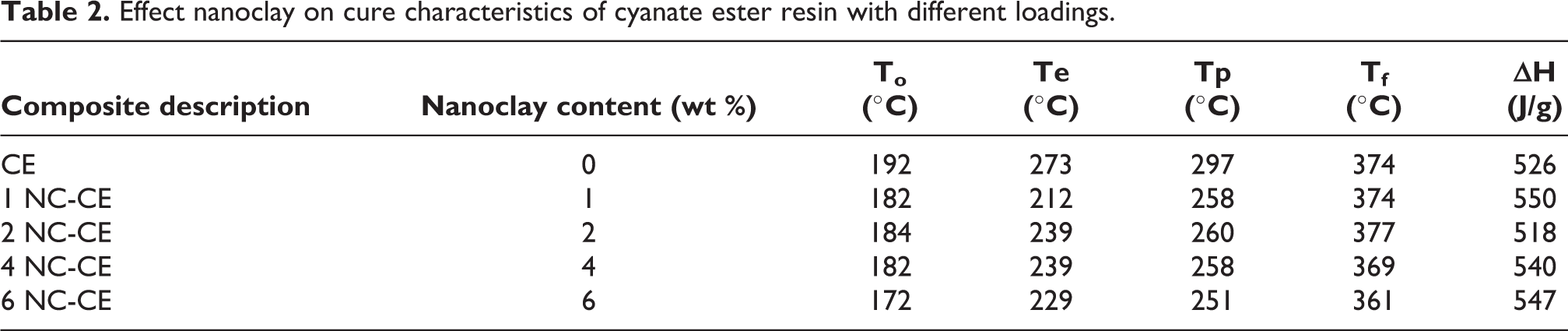
Figure 1, shows the curing behaviour of the neat CE resin and type I composites.Table 2, shows the cure initiation temperature (Ti), cure onset temperature (Te) and Peak cure temperature (Tp), end set of cure exotherm (Tf), heat generated during curing (ΔH). In the o-MMT nanoclay, active hydrogen groups (amine) present on the surface of nanoclay is showing catalytic effect on the curing of the CE. 6 This effect can be evidenced from the data shown in Table 2, where Ti, Te, Tp values shifted to lower temperatures with increase in heat of polymerisation (ΔH) for type I composites as compared to that of neat CE resin. From increase in ΔH, it can also be inferred that, cross link density increased due to addition of nanoclay to cyanate ester resin matrix. This can be attributed to amino functional groups present on the nanoclay that can react with cyanate ester resin. 16 However, change in ΔH is not uniform with the increased amount of addition of nanoclay. It can be seen that, ΔH value increased significantly for 1 wt% addition of nanoclay as it got exfoliated and thus interacted with more volume of matrix. At 2 wt% addition of nanoclay, as the intercalation started restricting the availabilityof nanoclay, ΔH value decreased marginally as compared to the reference sample. At 4 wt% and 6 wt% addition of nanoclay, by virtue of more amount of nanoclay, more interaction of amine groups of nanoclay takes place which increased ΔH.

DSC thermograms of neat cyanate ester resin and resin–nanoclay mixtures.
Effect nanoclay on cure characteristics of cyanate ester resin with different loadings.
Dispersion of nanoclay in type I composites
SAXS is choosen for dispersion studies considering its ability to probe the large area of material with subnanometer resolution. 20 It is reported to give useful insight on dispersion of partly ordered structures like intercalated, exfoliated clays. 21 Figure 2, shows the SAXS patterns of the as received nanoclay and cured type I composites.The results of d spacing values are shown in Table 3. It can be seen from Figure 2, that the characteristic peak observed for the pure nanoclay (o-MMT nanoclay) got subsided at 1 wt% nanoclay addition in type I composites, indicating that, clay platelets got exfoliated in the resin. 2 wt %, 4 wt %, 6 wt% of nanoclay filled cyanate ester resin composites have shown intercalation patterns. This can be attributed to the ability of organic part of o-MMT nanoclay which catalyses the curing of CE resin, leading to rapid gelation. This is known to retard the diffusion of the resin molecules into the galleries of nanoclay there by inhibiting extensive layer separation in 2 wt %, 4 wt %, 6 wt% of nanoclay filled cyanate ester resin composites. 22
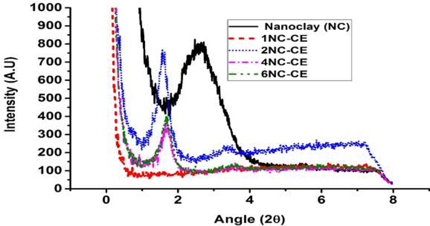
SAXS scans of nanoclay and type I composites.
d spacing of nanoclay and cyanate ester resin–nanoclay composites.

SAXS data indicates clay platelet segregation, whereas the SEM shows macroscopic distribution of clay in the matrix. Figure 3 shows SEM images of nanoclay dispersed in type I composites. The white spots highlighted in Figure 3, images are associated with silicon molecule, one of the main o-MMT nanoparticle constituents. Thus, the larger amount of white spots with uniform spread over the exposed area suggests the presence of o-MMT nanoclay in the matrix uniformly. 23
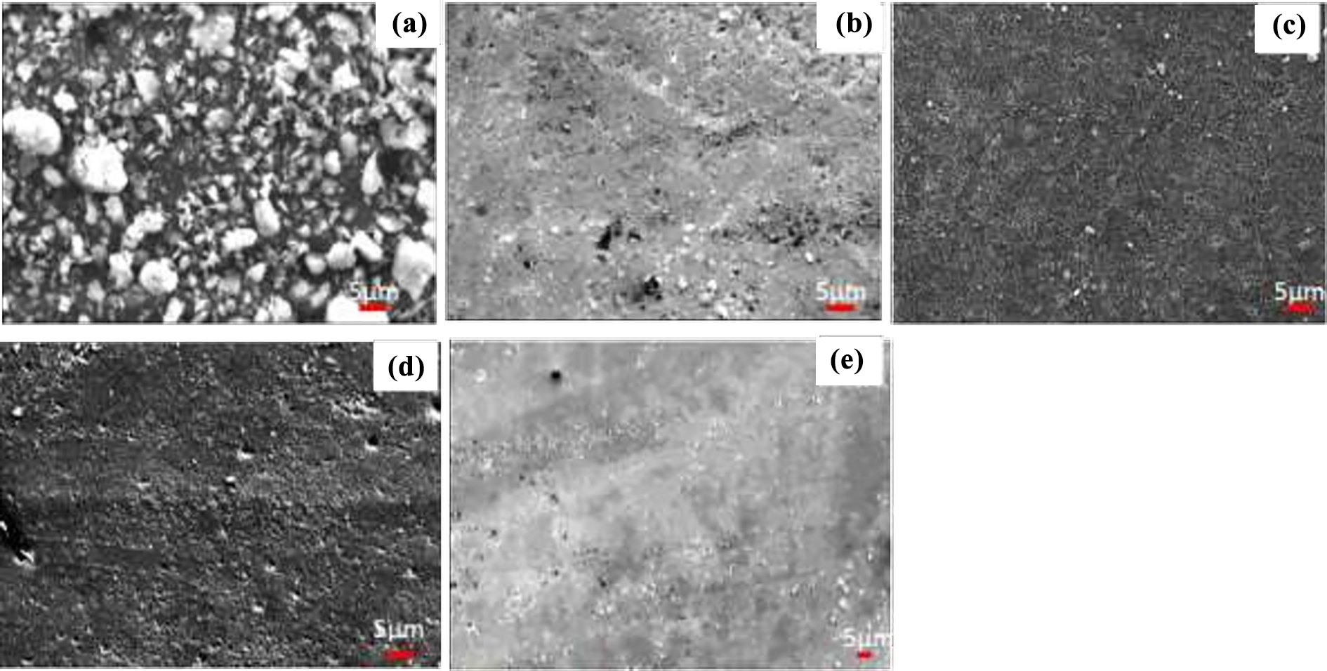
SEM images (a) As received o-MMT nanoclay (b) 1 wt% o-MMT nanoclay added cyanate ester composite (c) 2 wt% o-MMT nanoclay added cyanate ester composite (d) 4 wt% o-MMT nanclay added cyanate ester composite (e) 6 wt% o-MMT nanoclay added cyanate ester composite.
Effect of nanoclay content on viscosity of cyanate ester resin
The changes in viscosity of the cyanate ester resin due to different loadings of nanoclay is shown in Figure 4. The viscosity of pure cyanate ester resin is 30 cP which increased by around 50% at 1 wt% loading of o-MMT clay, which further increased to 420cP at 6 wt% addition. As o-MMT nanoclay is showing good interactions with the cyanate ester resin, a significant swelling of the clay galleries by the monomer would have lead to high relative viscosity. 24 Higher viscosity of the nanoclay modified resins, can reduce the resin extraction of the bleeder during the processing, resulting in a higher resin content for the fabricated composites. 9

Effect of nanoclay content loading (wt%) on viscosity of cyanate ester resin.
Density, fiber volume fraction (%Vf) of type II composites
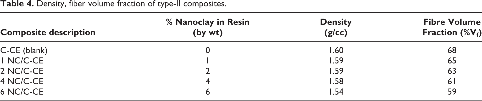
It can be seen from Table 4, that the density, fiber volume fraction of the composites decreased as the nanoclay content in cyanate ester resin increased. This is because of the poor resin squeeze out of the high viscous compositions as compared to the blank C-CE.4,9 This has resulted in reduced fiber volume fraction for the nanoclay added cyanate ester resin composite. As the fiber volume fraction is coming down density of the composites is also coming down.
Density, fiber volume fraction of type-II composites.
Thermal stability of the type I and type II composites
Figure 5, shows the thermo grams of as received nanoclay, type I and type II composites. Char residue at 900°C and temperature at 5% weight loss (T
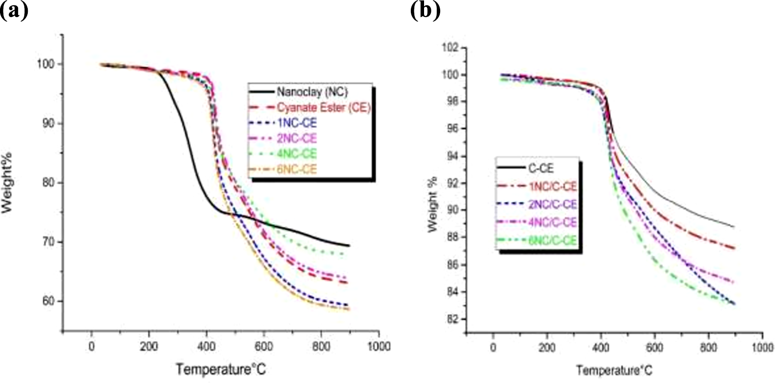
(a) TGA of nanoclay and type I composites, (b) TGA of type II composites.
Thermal stability of type-I and type-II composites.

The degradation of the CE resin in the composite under inert atmosphere can undergo as per reaction shown in equation-1. 3

On the otherhand, simultaneously along with the reaction (1), degradation of organic part of the nanoclay takes place as per equation-2. 4

However the oxygen species formed in the reaction (2) can trigger the degradation of the matrix further as per equation-3.

Thus o-MMT nanoclay reduces the thermal stability of the host matrix.
ILSS of type II composites
Figure 6, shows the effect of weight percentage of nanoclay on ILSS which increased by 17% at 2 wt % addition of nanoclay as compared to the blank C-CE composites. It can be observed from the SAXS data, that upto 1 wt% nanoclay got dispersed in CE resin, whereas from 2 wt% onwards, intercalation of nanoclay was observed. But the ILSS got improved significantly upto2 wt%. Even at 4 wt% nanoclay addition to CE resin, ILSS is better than the blank C-CE composite indicating that, intercalated nanoclay platelets can impart increased ILSS upto a critical concentration due to higher interface area and strong chemical bonds that they form at interface. 25 In the present study at 6 wt% of o-MMT nanoclay, ILSS has come down due to significant reduction in the fiber volume of the resultant composites.

ILSS of type-II composites.
Flexural strength of type II composites
Figure 7, shows that flexural strength increased upto 2 wt % nanoclay addition by about 21%. At 2 wt% addition of nanoclay, (even with low %Vf) the similar flexural strength as that of the 1 wt% nanoclay added composite were observed. At 4 wt% nanoclay addition, Vf of the composite is significantly lower as compared to the blank C-CE composite, yet it has displayed similar degree of flexural strength. This indicates, nanoclay platelets under intercalated conditions could impart significant positive influence on the overall flexural properties of the composites. This is because of the fact that, flexural failure is a combination of shear, compression, tensile failure. Intercalated nanoclay galleries offer significant resistant to tensile strength/compression of the matrix around them due to strong chemical bonds of the organic part of the nanoclay with the CE resin system which resists the change in the bond length. Thus additional chemical bonds adds to the overall strength of the composites. 26 However, beyond a critical reduction in Vf of the composite (6 wt% in present study), overall flexural strength has come down due to poor contribution from the fibers to the overall strength of the composite.

Flexural strength of type-II composites.
Effect of nanoclay content on ablative performance of type II composites
The results of the mass ablation rate of type II composite are presented in Table 6. The mass ablation rates have increased with increasing weight percentage of nanoclay content in type II composites as compared to blank type II composites at both heat fluxes (1250 kWm−2 and 5000 kWm−2). During the oxyacetylene torch ablation, several degradation processes operate simultaneously. The first one is chemical degradation of composite which involves endothermic pyrolysis of cyanate ester resin matrix into char with gaseous byproducts as shown in Eq. (1). The second one is mechanical erosion and removal of the char and fibers. Microstructure of the ablated surface gives inference on the mechanisms operated during the ablation. Ablation mechanisms are discussed in the light of microstructure of the ablated surface in the subsequent sections.
Mass ablation rate of type-II composites.
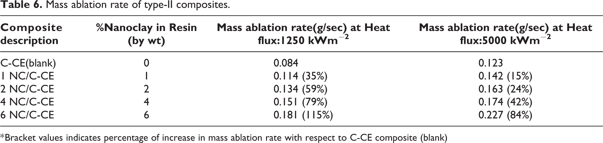
* Bracket values indicates percentage of increase in mass ablation rate with respect to C-CE composite (blank)
Microstructural behaviour of ablated surface of type II composites
Microstructures of ablated surfaces (tested at heat flux 1250 kWm−2) were shown in Figure 8. It can be seen that, in case of blank C-CE composite (Figure 8 (a)), there is no appreciable damage to the fibers. Highlighted zones of Figure 8 (a), indicates that, the traces of matrix are still present on the surface of the ablated composite. Even with low concentration (1 wt %) addition of nanoclay to C-CE composites, fiber breakage can be seen as indicated with arrows (Figure 8 (b)). As the clay content got increased in the C-CE composite, severe damage of the fibers was noticed with the damage spreading to the next ply across the thickness (encircled zone in Figure 8(c) & 8 (d)) of the composite. It is interesting to note that, in case of blank C-CE and 1 wt% C-CE, trace amounts of charred matrix is visible on the ablated surface (encircled zones in Figure 8 (a) and 8(b)), whereas in case of higher amount of nanoclay added composites (Figure 8(c) & 8 (d)), matrix vanished completely though the ablative flux levels for the test are same, indicating that, the species formed due to the degradation of organic part of nanoclay are reacting with char formed from the matrix and converting it into the gaseous states on the lines of the reaction 3 shown previously. Since the interfaces of the tows on the fiber becomes the matrix rich zones in the fabricated composites, degradation along the depth of the interface of between the tows will be maximum (reaction3 will be maximum) as highlighted in the encircled zones of the Figure 8 (c) & 8 (d). This leads to large craters and increased ablation rate.

Microstructure of samples tested at 1250 kWm−2 (a) Blank C-CE, encircled zones showing traces of matrix (b) 1 wt% nanoclay C-CE, arrows indicating fiber breakage, traces of matrix can be seen in encircled zones (c) 4 wt% nanoclay C-CE, arrows indicating fiber breakage, encircled zones indicating severe damage to fiber upto the next ply (d) Arrows indicating fiber breakage, encircled zone indicating severe damage across resin rich tow interface.
Microstructures of ablated surfaces (tested at heat flux 5000 kWm−2) are shown in Figure 9. It can be seen that, the ablative patterns at the higher flux of 5000 kWm−2 are different from the low flux of 1250 kWm−2. It can be seen that, there is deep damage to the matrix and fibers at high flux (Figure 9(a)). This is in contrast to almost uniform matrix removal for the nanoclay C-CE composites tested at a low flux of 1250 kWm−2. For 1 wt% nanoclay added C-CE composite, retained matrix can be seen to have porous openings indicating a gaseous products release during ablation (Figure 9 (b)). However, as the nanoclay amount has increased, more amount of molten clay/silica would have melted on the ablation surface (as per reaction 2) there by covering entire surface of ablating material. However, the reactions that are releasing gases (as per the equation 2&3) will try to lift the molten silica upwards and escape out, forming porous surface. This gives a ball like structure for the molten clay. The size of molten clay balls keep increasing with increasing clay content (Figure 9 (c) & 9 (d) 9(e) & (f)). This mechanism becomes more prominent at reasonably good amount of addition of nanoclay which is 4 wt% in this study. Large balls of molten clay formed on the surface of ablated fibers indicates liquid clay which was about to evaporate has condensed back in the form of liquid (Figure 9(d) & (e)). Thus continuous melting of the nanoclay protects the fibers from erosion. It can be seen that, as the fibers got protected, there is minimum damage to the fibers as seen in Figure 9(e). However, on the other hand, alternate mechanism operates, which involves reaction of oxidising species evolved from the organic part of o-MMT nanoclay, there by opening the craters for direct exposure of the fibers beneath the flame leading removal of fibers. These two mechanisms (melting of clay and protection of fibers, opening of the protective layer of clay and exposure of the composite beneath for the flame) compete with each other. Upto 4 wt% addition of nanoclay, clay melting and protection mechanism plays significant role. This can be evidenced from the fact that, upto 4 wt% addition of nanoclay, though ablation rate has increased, overall increase in the percentage ablation with respect to its blank is less as compared to the same samples tested at low heat flux (Table 6). At low heat flux, mechanism (i) is absent and only mechanism (ii) operates which lead to higher rate of ablation. However, at higher flux of 5000 kWm−2, for 6 wt% loading of nanoclay, mechanism (ii) dominates leading to complete removal of char with significant exposure of the fibers and removal of fibers (Figure 10(a)&(b)). Hence, at this loading there is abrupt raise in the rate of ablation as compared to the trend of ablation rate observed upto 4 wt% loading.

Microstructure of samples tested at 5000 K W/m2 a) Blank C-CE with significant amount of matrix present (b) 1wt% Nanoclay added C-CE with bubble like zones on the matrix (c) 1wt% nanoclay C-CE, with fiber breakage, traces of matrix can be seen (d) Molten clay balls on surface of 4 wt % nanoclay C-CE (e) Minimum damage to fibers due to continuous melting of nanoclay protect fiber from erosion in 4 wt% nanoclay C-CE (f) Large size molten nanoclay ball formed in 4wt % nanoclay added C-CE.

Both (a) & (b) shows the microstructure at different locations for 6 wt% nanoclay added C-CE tested at 5000 kWm−2.
Conclusions
Results obtained are summarized as below. Nanoclay in cyanate ester resin got dispersed upto 1 wt%, intercalated at 2 wt%, agglomerated at 4 wt% and 6 wt%. Even with intercalation, at 2 wt% nanoclay addition in type II composites, ILSS was found be maximum. Overall, 17%, 21% improvement in ILSS and flexural strength respectively were obtained. 2 wt% nanoclay addition can be considered as optimum for better mechanical properties for the C-CE composites with minimum compromise in the thermal stability and ablation performance. Thermal stability, char yield of C-CE composites have marginally decreased due to nanoclay addition. Mass ablation rate of type II composites, increased at all concentrations of nanoclay addition as compared to the blank. Though absolute mass ablation rate is higher for type II composite samples tested at 5000 kWm−2, percentage increase in mass ablation rate is lower as compared to mass ablation rates of same samples tested at low flux (1250 kWm−2). This is attributed to the additional protection from the molten clay at higher flux.
Footnotes
Declaration of conflicting interests
The author(s) declared no potential conflicts of interest with respect to the research, authorship, and/or publication of this article.
Funding
The author(s) received no financial support for the research, authorship, and/or publication of this article.