
Abstract
This manuscript presents an experimental and modeling approach in order to characterize the stiffness loss of bioabsorbable polymer filaments due to hydrolysis. In this regard, bioabsorbable suture yarns (poly(lactic-co-glycolic) acid—PLGA) were chosen as a representative material for the present investigation. The observed mechanical response was characterized by means of a thermodynamically consistent constitutive variational framework. Usually, two different damage variables are assumed to take place in this class of materials: a hydrolytic damage (long-term degradation) and a strain-driven damage (short-term degradation). This work concerns the proposition of a constitutive model that only considers the hydrolytic damage, in which a specific strain energy and a proper dissipation damage potential were tailored to model the tested material. A nonlinear curve fitting procedure based on Particle Swarm Optimization was performed to identify the constitutive parameters. A set of numerical simulations demonstrates the effectiveness of the proposed constitutive model to predict damage-induced creep and damage-induced stress relaxation, behaviors that can be used as design criteria in absorbable implants. The main achieved results show that the proposed constitutive approach leads to a simple but effective model capable to drive the first steps in the design of absorbable biomedical devices. The present variational framework can be extended to study the constitutive response of other bioabsorbable polymers, accounting for viscous and/or plastic behaviors.
1. Introduction
Over the last years, researches related to biodegradable/bioabsorbable polymers have increased considerably, ranging from studies concerning synthesis, processing and manufacturing to works focused on the mechanical characterization and constitutive modeling of these materials.1-7 Particularly in biomedical applications, absorbable polymers are broadly applied, covering from simple sutures yarns to complex orthopedic and vascular implants, such as screws, suture anchors, maxillofacial plates, vascular stents, among others.4,8-16 Concerning previously mentioned applications, the motivation that leads to the usage of bioabsorbable implants are manifold: to avoid complications resulting from a further surgical intervention to remove the implant; to reduce the so-called stress-shielding, i.e. bone re-absorption due to new load transfer paths; to act as a drug delivery vehicle during degradation; among others.
Focusing on the mechanical integrity and function of such polymeric devices, several issues have been reported concerning the loss of strength and stiffness in comparison to the metallic implants.14,15 In other words, the synthesis, design and manufacture of these polymeric devices must ensure that they are capable of withstanding the loads imposed during the period required to perform the mechanical stabilization function. On the other hand, the mechanical integrity (stiffness, strength, etc) of many of the bioabsorbable polymers used in biomedical applications is directly associated with the biomechanical and biochemical environment. These materials are well recognized to degrade by different chemical and physical mechanisms, such as hydrolysis, enzymatic degradation, oxidative degradation and mechanical degradation. Since the mechanisms that couples those chemical and physical effects at smaller scales are quite complex, the modeling of their constitutive behavior at the macroscale (device scale) is not trivial.
Within this context, Rajagopal et al. 17 presented a general constitutive framework for modeling degradation of polymers due to scission of the polymer chains. Based on the previous work, Soares et al. 1 proposed a continuum damage model to shed light on the interplay between deformation and hydrolytic degradation aiming at further numerical analyses of biodegradable stents made of poly(L-lactic acid) (PLLA). Employing three-dimensional finite element simulations, Vieira et al. 2 investigated the effect of the hydrolytic damage on the mechanical behavior of fibers composed of a blend of polylactic acid (PLA) and polycaprolactone (PCL) for ligament repair. Hayman et al. 10 contributed in this field investigating to what extent the mechanical behavior of PLLA stent fibers are prone to degrade under static and dynamic loading . In this case, fibers were modeled by a simple hyperelastic incompressible damage equation. Based on a sound variational constitutive approach within a finite element framework, de Castro et al. 3 developed a thermodynamically consistent coupled ductile-hydrolytic damage model for numerical simulations of bioabsorbable polymer implants. More recently, de Castro et al. 7 approached experimentally and numerically the non-homogeneous compression behavior of poly(lactic-co-glycolic) acid (PLGA). In such a study, the large strain mechanics of the material, the strain rate sensitivity and the effect of a heat-treatment procedure were investigated.
It is important mentioning that medical-grade polymers must fulfill several standards imposed by regulatory bodies in order to be approved for medical purposes, leading to proper manufacturing processes that directly impact on the overall costs of the device. Accordingly, it becomes clear that a better understanding about the ways degradation mechanisms affect the mechanical behavior of these polymers, certainly constitutes relevant information to both material analysis and design.
Motivated by these facts, this manuscript presents an experimental and modeling approach based on a simple constitutive damage model to characterize the stiffness loss of bioabsorbable polymer filaments due to hydrolysis. The hydrolytic degradation is modeled in a phenomenological way within the theoretical framework of the Continuum Damage Mechanics, where the material degradation is taken into account by means of a scalar variable, namely, damage.18,19 Briefly, this is generally quantified by values that range from 0 (undamaged material) to 1 (fully damaged material), and modulates the loss of stiffness due to degradation observed in experiments. In the present investigation, it is assumed that two major damage mechanisms occur in such materials. The first one is related to the degradation due to hydrolysis, i.e. chemical degradation of the material within an aqueous environment and with no mechanical loading. This damage source usually presents a long-term effect on the material integrity. The second one concerns to the damage induced by mechanical effects. Generally, this damage is driven by elastic and/or plastic strains, and it evolves in short-term periods. Based on this, only the first damage mechanism is considered in the present work.
As a representative of bioabsorbable polymers, PLGA-based suture yarns were chosen for the present investigation. When exposed to an aqueous environment, the PLGA degrades by hydrolysis into lactic and glycolic acids due to scission processes of the polymer chains, where two resulting monomers are then metabolized and eliminated from the body as carbon dioxide and water (Krebs cycle). 4 It have been reported that the degradation rate depends on the composition of lactic and glycolic acids, the molecular weight, the degree of crystallinity and the glass transition temperature. 20 This polymer have been successfully employed in biomedical devices, e.g.: sutures, scaffolds, basis to drug delivery systems and implants in general.4,7,20,21 In this regard, the experimental procedure is based on mechanical tensile tests performed after the yarns were subjected to predetermined periods within a temperature controlled bath in the absence of mechanical loads. This bath corresponds to a phosphate-buffered saline solution aiming to emulate the intracorporeal environment.
Regarding the constitutive modeling approach, a thermodynamically consistent variational framework well-established in literature was employed herein.3,22-27 A specific strain energy and a proper dissipation damage potential are proposed to model the tested material. Moreover, a nonlinear curve fitting procedure based on Particle Swarm Optimization (PSO) was used to identify the constitutive parameters in view of the experimental data. 28 In addition, a set of numerical results are presented in order to investigate the responses of the model to simulate local stress and strain behaviors that a bioabsorbable polymeric device could experienced within an intracorporeal environment.
Based on the aforementioned context, the main contributions of the present work to this research field are twofold: a) to present an experimental protocol to exclusively assess the influence of the hydrolytic damage on the mechanical response of the material, disregarding the mechanical damage; b) to propose a specific strain energy and a proper dissipation damage potential—and related modeling approach—to model the tested material and, consequently, to characterize the hydrolytic damage.
It is important to state that, although chemical and micromechanical phenomena rule the degradation processes of such polymers, this study intends to investigate the mechanical responses within a phenomenological (macroscopic) point of view. The present approach should be considered as the proposition of a simple constitutive model for practical purposes of analysis and design of bioabsorbable implants.
2. Material and methods
2.1. Experimental procedure
2.1.1. Samples
The tested samples were obtained from absorbable suture yarns widely used in many surgical procedures, which are commercially available as
2.1.2. Hydrolytic degradation procedure
The hydrolytic degradation procedure employed in this work consists in submitting the suture yarns to a temperature controlled (isothermal) bath. In order to emulate the intracorporeal environment (blood), right after removed from their packages, the yarns were placed in a phosphate-buffered saline solution (PBS, pH 7.4) at temperature of 37°C. 30 The temperature of the bath was controlled by a thermostatic incubator (Logen Scientific, LSTH-070A). Prior to mechanical tests, sets of 10 samples were kept in the aforementioned environment during the following periods: 0 h; 170 h (7 days); 340 h (14 days); 510 h (21 days); 680 h (28 days); 850 h (35 days); 995 h (41 days).
2.1.3. Mechanical test setup
Tensile tests were performed in air at room temperature using a universal mechanical testing machine (Shimadzu, AG-X Plus). In order to avoid technical issues concerning the use of conventional clamps—e.g.: slippage or premature rupture of the yarns close to the clamping site—a custom made gripping device was build for these experiments. This device is illustrated in Figure 1 and it was inspired by many commercial grips used for testing yarns, ropes, wires, etc.
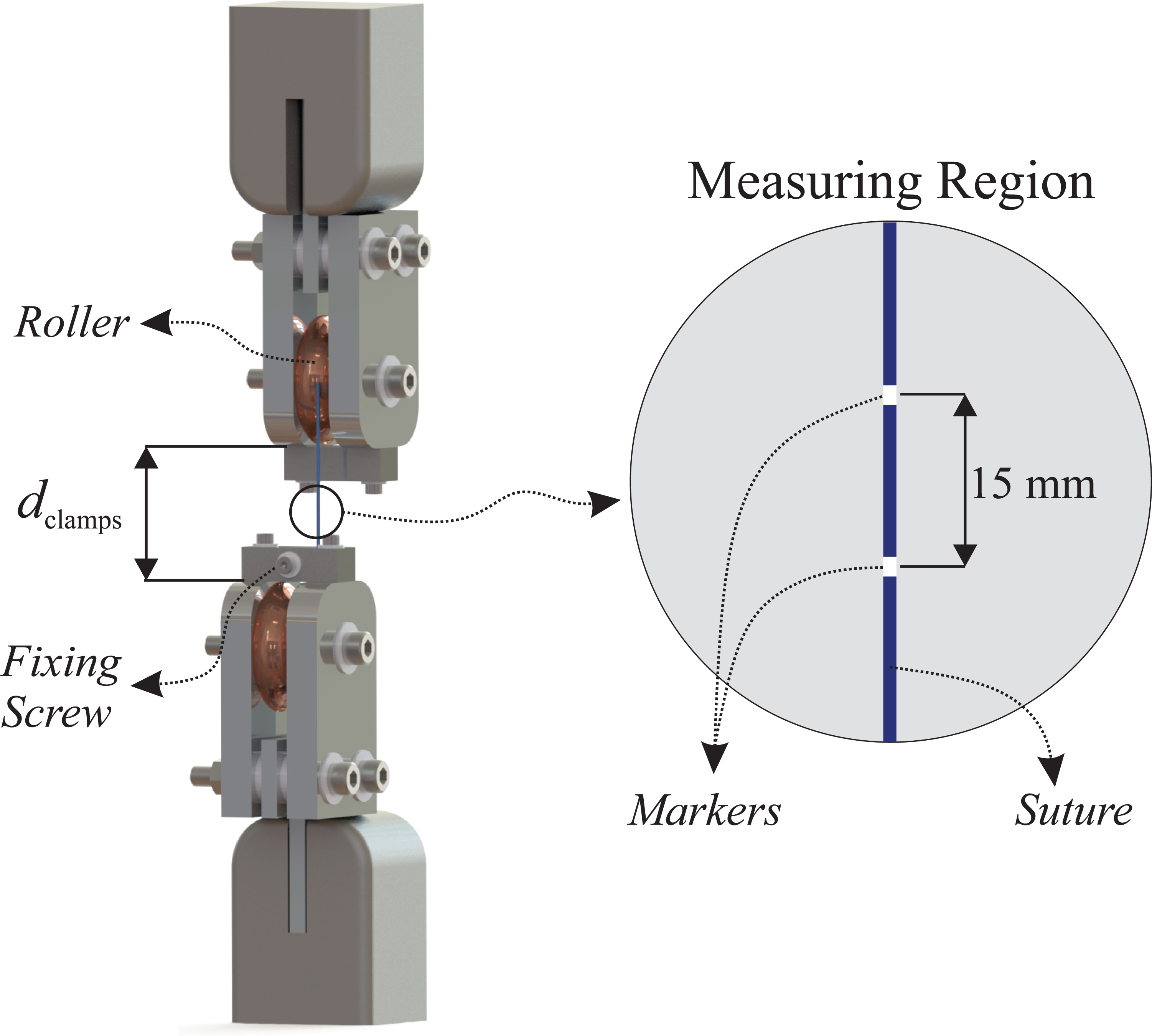
Illustrative representation of the custom made gripping device built for tensile tests of suture yarns. The relative displacement between markers were measured with the aid of a CCD camera.
The clamps were manufactured in chromed steel presenting U-shaped guide rollers (diameter of 50 mm), over which the yarn is rolled and fixed by screws (Figure 1). The smooth surface of the rollers acts preventing premature rupture of the samples in the clamping region. It is worth mentioning that, the clamping system was designed in order to ensure a correct alignment between the axial axis of the yarn and the loading axis of the machine, preventing then inaccurate measurements.
2.1.4. Testing protocol
The mechanical test protocol used in the present study is discussed as follows. After elapsed a predetermined bath time (see Section 2.1.2), a set of 10 samples was removed from the bath and submitted to tensile tests. Each sample was fixed with a distance between clamps of 50 mm (variable dclamps shown in Figure 1) and a pre-loading of 1.0 N was imposed in order to hold the yarn straight.
The yarns were marked with two white ink dots spaced 15 mm apart from each other and placed symmetrically in relation to the midpoint of the yearn (Figure 1). These markers were used to calculate the local stretch of the yarn during the test (further discussion in Section 2.1.5).
Thereafter, the tensile experiments were performed, consisting of displacement controlled monotonic tests at a displacement rate of 3 mm/min. All specimens were tested with this same—and relatively small—rate, since the present study does not investigate rate-dependent (viscous) effects.
2.1.5. Measured data
The measured data from the tensile tests are twofold: the force F and the relative axial displacement ua between markers. The latter data was obtained with the aid of a high-accuracy CCD camera device (Shimadzu, TRViewX500 S).
The axial stretch
As previously mentioned, the length L0 is predefined in 15 mm. Related to area A0, it was assumed that yarns have circular cross-sections at the measuring region limited by the markers. The cross-section diameter of each tested yarn were obtained from optical microscopy images (Figure 2). Five diameter measurements were performed throughout the observed region and the mean value was used to define the nominal transverse area A0.
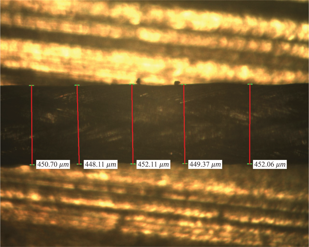
An example of the optical microscopy images used to measure the cross-section diameters of each tested yarn.
2.2. Numerical procedure
2.2.1. Constitutive modeling approach
The constitutive modeling approach employed in the present study is framed within a thermodynamically consistent variational framework well-established in literature.3,22-27 Based on this constitutive theory, the first Piola-Kirchhoff stress tensor

where
In the present modeling approach, the dissipated energy results only from hydrolysis. In this case, an internal variable named damage accounts for the dissipative behavior. Further details about this variable are discussed in the sequence.
2.2.2. General assumptions on damage
In the theory of the Continuum Damage Mechanics the material degradation is taken into account by an internal variable known as damage.18,19 This variable is generally quantified by a real number that ranges from 0 (undamaged material) to 1 (fully damaged material), and modulates the loss of stiffness due to degradation observed in experiments. Although the damage could be an anisotropic tensorial variable, an isotropic assumption—governed by one scalar damage variable—is generally suitable to capture a broad range of mechanical degradation phenomena.3,18,32-35 Moreover, this damage theory is consistently grounded within the Continuum Thermodynamics, 36 providing then a sound constitutive formulation.3,18,19,32
Within the present context, the degradation of the material is represented by a total damage variable D that is a function of two other damage variables, i.e.:

In Eq. (2), Dh accounts for the damage produced by the phenomenon of hydrolysis within a PBS solution and with no mechanical load. This type of damage is considered long-term, as it occurs in periods of time of days or months. The variable Dm represents the damage produced by mechanical action, usually driven by elastic and/or plastic deformations and occurring in short periods of time compared to those of hydrolysis. The function F as well as the evolution laws of Dh and Dm are in charge of coupling both effects, that is, how the mechanical damage Dm interacts with the hydrolytic Dh by changing the mechanical behavior of the material, and vice-versa.
This work is limited to study exclusively the influence of the hydrolytic damage Dh on the mechanical response of the material, disregarding the mechanical damage Dm. To this end, the following strategy was carried out: The degradation of the yarns due to immersion in aqueous solution was performed in the absence of mechanical loads (Section 2.1.2). The mechanical damage Dm usually starts after strains reach a critical value known as damage threshold.
18
Although this threshold is material dependent, in the present case is assumed that no mechanical damage occurs for strain values lower than 50% of the failure strain. The failure strain value clearly depends on the level of the achieved hydrolytic degradation (see Figure 4a, for example).

Evolution of the undeformed diameters of the sutures measured with the aid of optical microscopy images (see Figure 2). The time scale represents bath periods evaluated.

a) Experimental stress-stretch curves (symbols) and related constitutive predictions (lines) for each degradation period evaluated. The constitutive modeling was performed up to particular stretches at each degradation period in order to minimize strain-driven (short-term) damage effects (see discussion in Section 2.2.2). b) Hydrolytic damage evolution that models the mechanical degradation shown in a). The time scale represents bath periods evaluated.
2.2.3. Specific constitutive functions
According to the variational approach described in Section 2.2.1, one can note that the constitutive modeling is fully defined by the Helmholtz free energy ψ and the dissipation potential ϕ. Therefore, specific expressions are defined for these functions in the sequence.
Helmholtz free energy
Since the present work concerns the modeling of yarns under tensile states, the following classical transversely-isotropic hyperelastic form is proposed:

where ψiso is the isotropic strain energy potential and ψa is the fiber-reinforced (anisotropic) strain energy potential that takes into account the strains projected in the axial direction of the yarn. The use of an anisotropic reinforcement term is justified due to the strong axial stiffness resulting from the manufacture of the yarns. For this reason, it is considered that the contribution of the potential ψa is considerably greater than that of ψiso for axial strains, being the latter disregarded for the present model, allowing for simpler scalar mathematical expressions.
Differently from classical damage formulations, where the damage variable acts linearly on an undamaged strain energy, 18 a nonlinear expression is proposed:

where
From Eq. (4), one can see that the damage variable not only changes the linear stiffness of the model (ruled by the parameter κ), but it also modifies the stiffness shape modeled by the exponential function. Moreover, non zero strain energy is only possible for positive (tensile) strain states.
Dissipation potential
As previously stated in Section 2.2.2, it is assumed herein that changes in the mechanical integrity of the sutures only occurs by hydrolysis. Based on this, it is proposed that the hydrolytic damage in the axial direction of the yarn is ruled by the following dissipation potential:
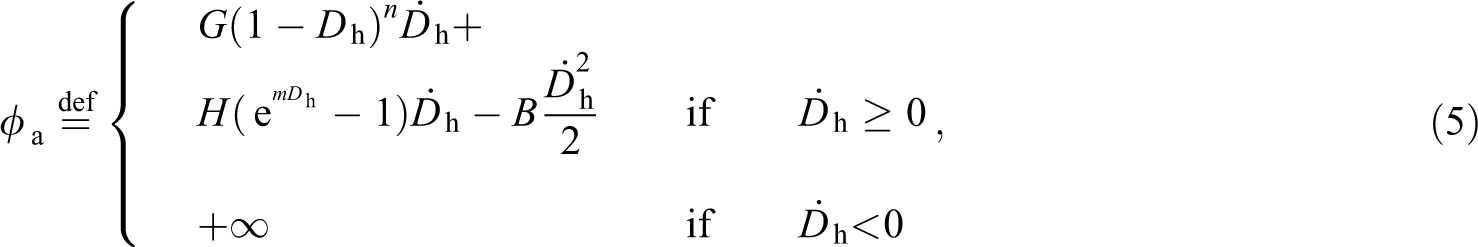
where
2.2.4. Identification of the constitutive parameters
The identification of the constitutive parameters follows the classical nonlinear curve fitting procedure between the experimental data and the theoretical predictions. In this regard, the resulting optimization problem is solved by the Particle Swarm Optimization (PSO), which is a heuristic algorithm with non-local characteristics. 28
Specifically, the proposed identification strategy seeks to find the set of constitutive parameters {κ, α, β, G, n, H, m, B}, associated with the functions (4) and (5), that better fits the numerical responses to the experimental axial stress-stretch mean curves. It is important to emphasize that only the hydrolytic damage is considered in the present study. Moreover, to be consistent with the assumed hypotheses of item 2 (Section 2.2.2), the numerical simulations are restrained to strain values lower than the threshold of 50% of the failure strains.
3. Results
The undeformed diameters of the yarns, measured with the aid of optical microscopy images (Figure 2), are shown in Figure 3.
The axial stress-stretch curves and the corresponding numerical predictions for each tested degradation period are shown in Figure 4a. The corresponding hydrolytic damage evolution is plotted in Figure 4b.
All the numerical curves presented in Figure 4 depend on the same set of model parameters identified according to the procedure described in Section 2.2.4. These parameters are listed in Table 1.
Constitutive parameters retrieved from the identification procedure.

The time history of the stresses at failure, retrieved from the experimental curves of Figure 4a, is depicted in Figure 5.

Evolution of the stresses at failure obtained from Figure 4a. The time scale represents bath periods evaluated.
Finally, in order to better evaluate the performance of the proposed constitutive model, two classical mechanical conditions are simulated. The first one corresponds to creep tests for three stress values: 15, 25 and 50 MPa (Figure 6a). The second one corresponds to stress relaxation tests performed for three stretch values: 1.02, 1.05 and 1.10. These results are shown in Figure 6b.
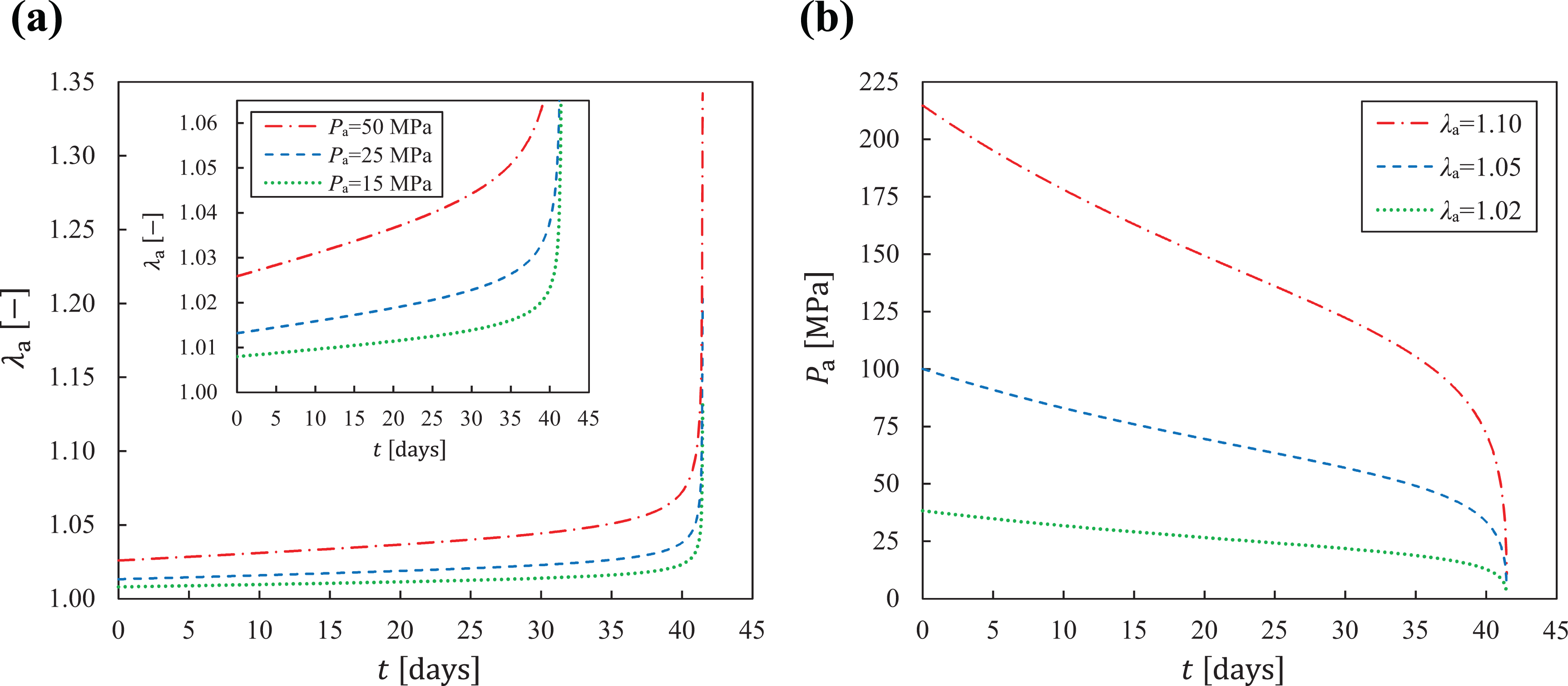
Constitutive behavior of the proposed model under different mechanical conditions. a) Creep tests for three constant stress values: 15, 25 and 50 MPa. The inside graph is constrained up to
4. Discussion
4.1. On the experimental results
An important variable needed to calculate the axial stress is the undeformed diameter of the yarn, whose evolution for different periods of bath immersion is shown in Figure 3. Some polymers could experience mass loss due to diffusion mechanisms resulting from degradation processes.2,4 Based on this, it was expected that diameters would reduce when time spans. Conversely, the mean diameters slightly increased up to 15 days, keeping almost constant afterwards. Since tested sutures are braided, they are likely to experience a small amount of swelling in the first days within the bath. Based on this behavior, one can concluded that the observed loss of stiffness results exclusively from the hydrolytic degradation process and not from geometry changes.
As can be seen in Figure 4a, both stiffness and strength of yarns reduce their values proportionally to the period of bath immersion, behavior that was already expected and clearly indicates mechanical degradation.1,3,7 Nevertheless, due to the nonlinearities involved—both material and geometrical—the understanding of how much the hydrolytic degradation changes the stiffness over time is not straightforward in the present case.
Regarding the strength of the sutures, Figure 5, one can see that, up to 25 days, the failure points decay at an almost constant rate, followed by a significant decrease until no more strength is verified at 41 days. This material response is in line with other experimental tests in absorbable sutures reported in literature.13,30,41 Despite stress at failure concerns an important quantity to be taken into account in mechanical design, biomedical devices could consider other design criteria, such as deformation level and stiffness.1,3 For the present application, if at a certain time of degradation the surrounding tissue is not properly healed, the load continues to be fully supported by the suture which, if degraded, can deform more than is necessary to fulfill its function. Such mechanical behavior, namely, damage-induced creep, is better explored in the numerical results discussed in Section 4.2.
4.2. On the constitutive modeling
One can see in Figure 4a that the proposed constitutive model presents a satisfactory fitting to the experimental stress-stretch mean curves. The constitutive parameters that model these curves, which were retrieved from the identification procedure, are listed in Table 1.
It is important to note that the parameters α and β within the Helmholtz free energy expression model the exponential character of material stiffness (see Eq. (4)). Therefore, they are extremely relevant to the curve fitting. In this regard, particular discussion concerns the parameter β. One can see in Eq. (4) that the parameter β was introduced to couple the hydrolytic damage variable in a nonlinear manner with the stiffness. Since its identified value is not null (0.43044 in the present case), it showed to be important for a better characterization of the material behavior.
Once the identification of the material parameters is performed, one can verify how the hydrolytic damage evolves on modifying the material responses. One of the major points to be achieved with the present approach consists of finding this damage pattern. The hydrolytic damage evolution of the studied cases is plotted in Figure 4b. This curve is ruled by the dissipation potential (5) with the parameters listed in Table 1. Up to 30 days of degradation, the damage curve evolves in slightly nonlinear shape, presenting approximately 40% of mechanical degradation. This behavior is mainly ruled by the power law expression of Eq. (5). Afterwards, the remaining 60% of degradation occurs in the last 10 days. Throughout this period, one can verify that the hydrolytic degradation increases considerably at a high rate. This abrupt changes on the damage pattern can not be proper modeled only by the power law function. For this reason that an exponential contribution was included in the potential (5).
With the identified parameters at hand, it is possible to investigate the characteristics of the model to predict other mechanical states, in addition to those of tensile tests. In view of this, two classical local mechanical conditions are proposed for these simulations: creep and stress relaxation, which are shown in Figure 6a and Figure 6b, respectively. These mechanical states are usually found in bioabsorbable polymeric medical devices.1,3 It is worth mentioning that the terms creep and stress relaxation are commonly employed in the context of viscoelastic materials. On the other hand, continuum damage formulations, as the present one, can induce creep and stress relaxation, even if no viscous effects are accounted for. This is known in literature as damage-induced creep and damage-induced stress relaxation. 42
Two aspects can be drawn from the creep results shown in Figure 6a. Firstly, for the three constant stress values simulated, the overall deformation histories follow analogous paths, i.e. up to the first 30 days, damage induces an increase of stretch at an almost constant rate, followed by a larger deformation between days 31 and 41. This constitutive behavior clearly reflects the degradation pattern shown in Figure 4b. The second issue concerns the manner in which the stretch evolves for different stress values, as highlighted in the inset graph of Figure 6a. Although all predictions are ruled by the same degradation pattern, when the stress value increases, the rate in which the stretch evolves also increases. These two described behaviors in the creep tests occur, analogously, in the relaxation tests of Figure 6b, but in terms of stress.
Based on the aforementioned mechanical behaviors, one can extend the previous discussion from simple suture yarns to more complex polymeric implants (with intricate geometries). As clearly reported in previous works,1,3 biodegradable medical implants are likely to experience non-homogeneous deformation fields. This means that some regions of the device will degrade faster than others due to coupled damage sources, which in turn can lead to failure prior to expected.
It is worth emphasizing that mechanical (strain-driven) and coupled hydrolytic-mechanical damage effects are not considered in the present investigation (see Section 2.2.2), which are likely to speed up degradation. Moreover, experimental studies 10 show that both static and dynamic loading increase degradation rates of poly-l-lactic acid (PLLA) fibers, corroborating with previous mentioned hypothesis. Moreover, viscoelastic-viscoplastic effects are observed in the constitutive behavior of these materials. 3 In this way, depending on the desired application, such behaviors must be accounted for in the final design of the device.
On the other hand, due to the several and complex material behaviors observed in bioabsorbable polymers, a fully constitutive characterization requires not only a large amount of experiments, but also the development of complex mathematical models, increasing time and costs spent with the project. In this regard, it is important reinforcing that the present strategy provides an initial design criteria for bioabsorbable medical-grade polymers. In other words, if the chosen material meets a certain design criteria, where only the hydrolytic damage is taken into account,—e.g.: maximum acceptable strains under creep, as those shown in Figure 6a—one can give a step further into the project in order to consider other phenomena. Otherwise, the selected material could be disregarded for that application.
In addition, it is worth to highlight that, if the studied polymer presents more complex mechanical behaviors, such as viscoelaticity, viscoplaticity and other damage effects, the variational constitutive framework employed herein (Section 2.2.1) could be extended (in a thermodynamically consistent way) to consider these phenomena. Further details on this subject are addressed in Appendix A.
5. Conclusions
The main achieved results show that the proposed constitutive approach leads to a simple but effective model capable to drive the first steps in the design of absorbable biomedical devices. Particularly for the material investigated, a nonlinear behavior was verified coupling the hydrolytic damage variable with the Helmholtz free energy in an exponential manner. Moreover, the damage history retrieved from the modeling procedure shows a considerable increase on the mechanical degradation as a consequence of the exponential term included in the model. In the present case, 60% of the total material stiffness was degraded within the last 10 days in an overall test of 40 days. The functional form of the proposed dissipation damage potential was crucial to model such behavior. A set of numerical simulation demonstrated the effectiveness of the proposed constitutive model to predict damage-induced creep and damage-induced stress relaxation, behaviors that can be used as design criteria in absorbable implants. The present constitutive framework can be consistently extended to study the material response of other bioabsorbable polymers filaments, accounting for viscous and/or plastic behaviors.
Footnotes
Acknowledgments
The authors would like to thank the following agencies and personnel: National Council for Scientific and Technological Development (CNPq); Coordination for the Improvement of Higher Education Personnel (CAPES); the staffs from the Laboratory of Multifunctional Materials and the Laboratory of Manufacturing Processes, both located within the Community University of Chapecó Region facilities.
Declaration of conflicting interests
The author(s) declared no potential conflicts of interest with respect to the research, authorship, and/or publication of this article.
Funding
The author(s) received no financial support for the research, authorship, and/or publication of this article.