
Abstract
A highly accurate X-ray damage characterization technique was used in this study to investigate the correlation between hole damage, tool wear and thrust force in drilling of carbon fibre reinforced laminates. Woven carbon/epoxy panels were drilled with a twist tool for 592 holes and the internal damage induced by drilling was investigated by high-resolution penetrant-enhanced X-radiography for comparison with damage evaluated by visual inspection. The study shows that the dominant damage mode induced by drilling is delamination and that tool wear has a significant effect on the size of the delaminated area. The analyses also show that the delaminated areas estimated by visual inspection are much smaller than those identified by X-radiography. This finding indicates that visual observation techniques may provide dangerously unconservative indications and should be used in association with more reliable damage evaluation methods to assess the hole quality of drilled carbon fibre reinforced composites.
Keywords
Introduction
Polymer-matrix composites are increasingly used to replace conventional metallic materials in many structural applications, owing to their excellent mechanical properties, such as high specific strength and stiffness, good fatigue behaviour, low thermal expansion and outstanding corrosion resistance. Even though composite components with complex geometries can be often obtained by single-step integral manufacturing processes, most composite structures generally require fastened or bonded joints to assemble individual components and transfer loads across structural parts. Mechanical fastening, in which the components are joined using bolts, rivets or screws, is still the dominant way of joining laminated composites because of several advantages over adhesive bonding: fastened joints do not require special surface preparation, permit disassembly for inspection or maintenance and are not greatly affected by thermal or humidity degradation. 1 The structural performance of composite joints is however heavily influenced by the quality of the machined holes, as drilling defects may act as sources for damage initiation and propagation under static and fatigue loads and may thus seriously degrade the strength properties of composite structures. An accurate assessment of the damage introduced by drilling in composite materials is therefore of crucial importance in order to identify the drilling procedures and the tool wear conditions that ensure the hole quality required for a reliable use of drilled composite components.
Different types of damage can be introduced by the drilling process in laminated composite materials. Damage modes include delaminations, intralaminar cracks, spalling (where small parts of the outer layers are peeled off from the laminate surface), fibre fuzzing (uncut groups of fibres protruding to the interior of the hole). 2 Delamination, i.e. the separation between adjacent layers due to the failure of the interply resin interface, is generally considered the most critical defect that can be produced by drilling operations, because of its key role in controlling the strength and the service life of the machined component.3-5 Delaminations are generated at the entry or exit sides of the workpiece by two distinct mechanisms, 6 which are schematically shown in Figure 1. Peel-up delamination develops at the interfaces close to the hole entry as a consequence of the upward axial force exerted on the cut layers by the drill flute; this force tends to move the upper layers apart from the uncut layers, thus introducing a peeling action that is responsible for the initiation and growth of the delamination at the hole edge. Push-out delamination occurs between layers near the hole exit when the drill approaches the bottom surface of the workpiece; the intact region of the laminate deflects under the force applied by the drill and delaminations initiate when the thrust force reaches a critical value corresponding to the condition of crack propagation at the interface between the layers. Push-out delaminations have been generally observed to be more extensive, and therefore more detrimental to the structural performance of the component, than peel-up delaminations.3,7

Schematic mechanisms for entry (peel-up) and exit (push-out) delaminations.
The severity of delamination damage occurring at the hole during drilling is therefore greatly dependent on the magnitude of the axial thrust force exerted by the tool on the workpiece, which is generated by the contact of the cutting and chisel edges with the composite. Continuous monitoring of the thrust force as a function of drilling time may thus provide valuable information on the interaction between the tool and the material and on the current quality of the cutting surfaces during the drilling process.
A strong correlation also exists between the wear that inevitably initiates and grows in the tool as a consequence of the drilling operations and the damage introduced around the hole by drilling.3,8 Significant increases in delamination size with growing tool wear were for example observed in different classes of fibre-reinforced polymer composites when subjected to sequences of successive drilling operations.8-16 The increase in delamination damage was attributed to the rise in thrust force associated with the accumulation of wear in the drilling tool. Tool wear, which is caused by the high contact pressure and the associated temperature conditions occurring at the surface of the tool during drilling, results in a progressive loss of tool material that modifies the geometry of the original profile of the cutting edge and therefore reduces its efficiency for material removal. The heat generated during drilling of fibre reinforced polymer composites is however significantly less than that generated when drilling metal parts, as a consequence of the brittle chip formation in reinforced plastics as opposed to the more ductile and energy-absorbing chip formation in metals. 17 The maximum temperatures developing within the tool during drilling of polymer composites are therefore substantially reduced with respect to those reached in metals and this is especially true for carbon fibre reinforced plastics, which ensure an efficient heat dissipation due to the good thermal conductivity of carbon fibres. 18 Tool wear generated by drilling of carbon reinforced polymers is therefore typically dominated by the mechanical actions of abrasion and indentation exerted by the hard carbon fibres on the tool surface, while thermo-chemical phenomena usually play only a minor role on tool degradation.17,19
Because of their brittle behaviour, drilling of fibre reinforced polymers results in segmented or powder-like chips, characterized by a series of progressive fractures across the fibres or at the fibre/matrix interface. 20 The lack of a continuous chip decreases the chance of significant abrasive wear on the rake face, and tool wear generated by polymer composites mainly consists of flank wear and rounding or micro chipping of the cutting edge, while rake wear is usually negligible or absent.10,11,21-23 For these reasons, the wear developing on drilling tools when machining composite materials is generally quantified by parameters measured on the flank surface (such as the width of the wear land VBB or the length of removed material at the outer tool corner VBC) 20 or by quantities characterizing the sharpness of the cutting edge, such as the cutting edge radius (CER). 10
Different techniques have been proposed to assess the extent of the delaminations induced by drilling in composite materials.4,7,24 The usual approach is that of evaluating the delaminations at the entry and exit sides of the workpiece by optical inspection methods, where the image of the workpiece surface is acquired through optical microscopy or with the use of digital scanners or high magnification CCD cameras.4,7 Alternative and more advanced techniques, which include X-ray projectional or tomographic radiography,14,25-27 ultrasonic C-scans, 28 moiré interferometry, 29 have been also employed to reveal drilling damage. These methods have been however very rarely applied in practice, mainly because of the increased complexity involved in their use in comparison to visual inspection approaches.
In this regard, it is important to remark that on translucent composites such as glass fibre reinforced polymers the full size of the internal damage can be indeed accurately measured by simple visual observation, which may be aided by the infiltration of a suitable dye into the material or by the use of a light source placed at the back side of the drilled workpiece. 30 In contrast, the characterization of damage by optical methods is much more problematic in carbon fibre composites, which, because of their opaqueness to visible light, make the detection of subsurface defects extremely difficult, if not impossible. As a matter of fact, while damage modes occurring at the surface, such as spalling, fibre fuzzing or matrix cracking, can be visually observed and characterized, the presence of internal delaminations may be only inferred by the analysis of surface features, such as matrix cracks or out-of-plane displacements of the external layers, which are assumed to be indicators of some underlying interlaminar damage. It is therefore evident that the assessment of delamination damage performed by optical inspections may only provide a qualitative, more than a quantitative, estimate of the actual damage extent and may lead to largely unconservative indications on its severity. To the best of authors’ knowledge, however, all published investigations aimed at characterizing the relationship between tool wear and drilling damage in carbon composites over significantly wide ranges of tool wear conditions have been carried out using visual methods to quantify hole damage.8,10-13,15,16,31 This lack of accurate and reliable damage data is particularly critical since, as shown by the findings of this study, the discrepancy between the actual size of the delaminated area and that estimated by direct observation may become very large with increasing tool wear levels.
The aim of the experimental analyses presented in this paper is, therefore, that of investigating, by means of a very accurate technique for damage assessment, the correlation between drilling damage and quantitative flank wear and thrust force parameters that can be measured during drilling operations to indirectly monitor the degradation of hole quality. Very detailed pictures of damage induced by drilling on a carbon/epoxy laminate were obtained by high-resolution penetrant-enhanced X-radiography, and the information on delamination size provided by X-ray images was compared to that obtained by optical analyses.
The acquired data are examined and discussed in the paper to assess the influence of the accumulation of tool wear on the quality of the drilled holes and to highlight the importance of the adoption of appropriate techniques for the evaluation of drilling-induced damage.
Experimental
Material and drilling procedures
Laminated panels made of plain weave carbon/epoxy prepreg layers (Texipreg T300/ET442 supplied by Seal, Italy) laid up with a [0]6 stacking sequence and with a thickness of 2.1 mm (Figure S1) were used in this study to investigate the relationship between the wear of the drilling tool and the damage induced by drilling in the material. The composite panels (500 mm × 500 mm in size) were cured under vacuum in autoclave at a pressure of 6 bar and a maximum temperature of 120°C. After consolidation, strips 80 mm wide and 400 mm long were cut from the panels for the drilling tests.
A solid carbide two-flute twist drill (supplied by Emmedue Euro Tools, Italy), with a diameter of 6 mm and an overall length of 66 mm, was selected for the experiments. The tool, shown in Figure 2, has a flute length of 25 mm, with a helix angle of 20° and a point angle of 144°. It should be pointed out that even though special tool geometries or materials, such as coated carbides and polycrystalline diamond, have been specifically developed for drilling fibre-reinforced composites, 31 solid carbide twist drills are still largely used in the current industrial practice, because of their general availability and much lower cost as compared to more specialized tools.
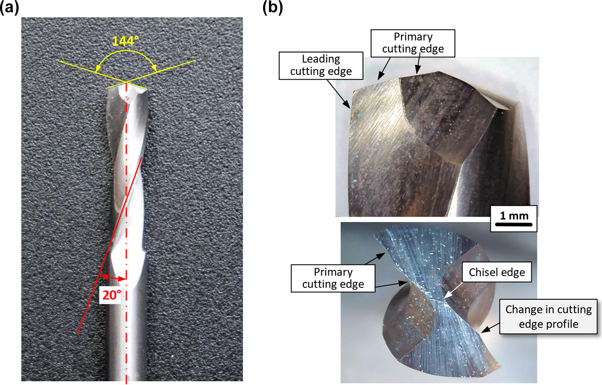
Main geometric parameters (a) and features (b) of the drill used in the study.
The drilling tests were conducted on a universal machining centre (DMG Mori DMU 60P) at a rotation speed of 18,000 rpm and a feed rate of 2400 mm/min. During the operations, the composite strips were clamped to a specially designed fixture and a quartz dynamometer with built-in charge amplifiers (Kistler 9765A) was used to measure the thrust force generated by drilling (Figure S2). The analogue signals from the dynamometer were digitized by an A/D board (National Instruments NI USB 6251) at a sampling rate of 20 kSamples/s and finally recorded on a personal computer controlled by an in-house developed LabView acquisition package. A total number of 592 holes, corresponding to a cutting length of almost 1250 mm, were drilled during the testing program.
Characterization of drilling damage and tool wear
As described in the introduction, penetrant-enhanced X-radiography was used to achieve the highest possible accuracy in the characterization and quantification of the damage induced by drilling in the workpiece. To this aim, the drilled composite strips were immersed for 5 h in a radio-opaque zinc-iodide penetrant solution (60 g zinc-iodide, 10 ml water, 10 ml isopropyl alcohol and 6 ml Kodak Photoflo) to infiltrate the damaged regions at the hole. Zinc-iodide is commonly used to investigate damage in composite laminates 32 because of its good opacity to X-rays and low toxicity as compared to other radio-opaque substances such as diiodomethane and tetrabromoethane. Moreover, zinc-iodide solutions were shown not to affect existing damage modes, unless applied for prolonged periods and under high stress levels. 33 After immersion, the specimens were carefully cleaned with acetone and radiographed in a Faxitron 43855A cabinet system provided with a 500 µm micro-focus X-ray tube. The composite samples were placed directly above the radiographic film at a distance of about 60 cm from the X-ray tube and exposed to radiation for 2 min using 20 kV and 3 mA tube voltage and current respectively. The use of a micro-focus X-ray source and of a radiographic film characterized by ultra-fine grain and very high contrast (Agfa Structurix D4) allowed to obtain highly detailed pictures of the drilling damage. The exposed films were then processed and digital images of the developed films were acquired for observation and measurement of hole damage using a digital scanner with a resolution of 47 pixel/mm. An image analysis software was finally used for measuring the delaminated areas in the digitized radiographs.
It is worth recalling that conventional X-ray images show the projection on the laminate plane of the damage modes occurring at all interfaces and layers within the laminate. In order to acquire additional information on the through thickness distribution of internal delaminations, separate radiographs of the drilled laminates were taken at different angles (+10° and −10°) and stereoscopic observations were performed on the acquired X-ray stereo pairs to visualize a three-dimensional map of internal damage and identify delaminations at specific interfaces. 34
Images of the holes at the entry and exit sides of the composite panels were also acquired with the same scanner used for the X radiographs and examined to reveal surface damage mechanisms and to estimate delamination damage for subsequent comparison with delamination extents obtained by X-radiography.
The evolution of tool wear with drilling was characterized by monitoring the flank wear length VBc at the outer corners of the two cutting edges, as defined in the standard ISO 3685:1993 35 and schematically illustrated in Figure 3. The VBc length was measured on digital images of the profile edges captured at predefined intervals of the drilling tests (ranging from 6 to 16 holes) with the aid of a Canon EOS 650D digital camera mounted on a Nikon SMZ-2 T optical stereomicroscope. In addition to being relatively easy to measure, the VBc parameter is a sensitive 36 indicator of flank degradation as it provides information on wear occurring at the periphery of the cutting tool, where the cutting speed is the highest and the largest amount of wear may thus be expected. The same parameter was used to monitor tool wear in a number of investigations into the response to drilling of laminated composite materials.13,20,37,38

Flank wear length VBc.
Results and discussion
Tool wear and thrust force
Figure 4 shows typical thrust force histories measured during drilling at various numbers of holes. The force-time curves consist of three main stages, which include the entry of the drilling tool into the material, the full engagement of the primary cutting edges, and the exit of the drill from the back surface of the workpiece. It is seen that the initial rising portion of all force histories, irrespectively of the number of drilled holes, exhibits two characteristic discontinuities (marked by the arrows 1 and 2), which are due to the involvement in the drilling process of specific geometrical features of the tool point; point 2, in particular, was observed to signal the entry in the workpiece of the primary cutting edges in correspondence to the sudden change in the profile shape indicated in Figure 2.
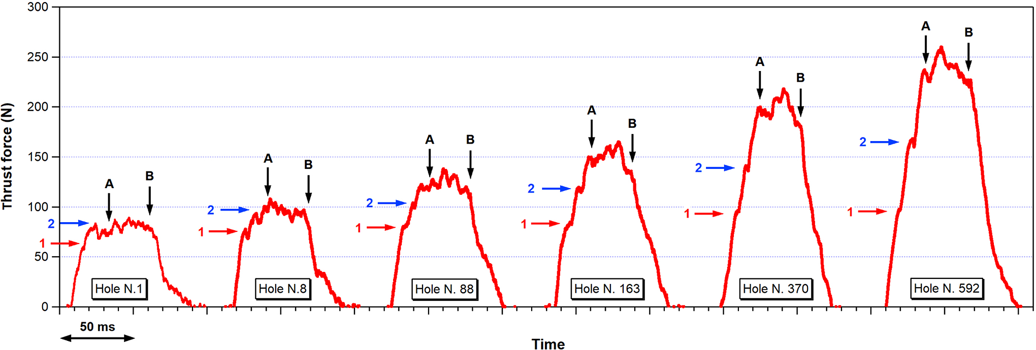
Histories of thrust force measured for different numbers of holes.
The second stage, which begins with the full engagement of the primary cutting edges within the workpiece (point A), is characterized by a force level that remains approximately constant as the tool progresses through the laminate thickness; the oscillations that can be seen in the force signal are mainly due to the heterogeneity of the material and to the effect of the continuously varying angle between fibre orientation and cutting direction. 39
In the third stage, the thrust force starts decreasing as soon as the chisel edge reaches the back surface of the laminate (point B), followed by the gradual exit of the primary cutting edges from the workpiece. The force drops finally to zero when the corners of the primary cutting edges exit the hole and reaming starts taking place, with the contact between the drilling tool and the workpiece only occurring between the leading cutting edges and the hole wall.
The force-time histories plotted in Figure 4 show that the peak force increases significantly with the number of drilled holes. As an example, the maximum force rises from about 90 N for the first hole to more than 250 N for hole number 592, with an increase of almost three times. The peak values of the thrust force histories measured during drilling are reported in the graph of Figure 5 as a function of the number of the drilled holes. After an increase from 89 N to 100 N from the first to the second hole, the peak force grows at a much lower rate, which remains approximately constant over the entire range of drilling operations performed in the study. It is well known that the rise in force with drilling time is associated with the accumulation of tool wear, which leads to the deterioration of the surface quality of the cutting edges and to changes in their geometry that result in a less efficient removal of material.3,7 In particular, the rise in the cutting force observed after the first hole may be attributed to initial phenomena of microchipping at preexisting weak points, 11 while the region of constant rate is associated with the rounding of the originally sharp corners of the cutting edges and to the gradual progression of abrasive wear that accumulate at the flank of the drill with drilling operations. 20

Peak values of thrust force as a function of the number of drilled holes.
The flank wear VBc measured at the outer corner of the cutting edges was selected as a tool wear indicator for a quantitative assessment of the degradation of the drilling tool. The choice of characterizing tool wear by a local measurement at the periphery of the cutting edge is also suggested by an analysis of the force-time curves, which show that the thrust forces measured at the discontinuity points 1, 2 and at point A (corresponding to the whole engagement of the main cutting edge) grow at different rates with the number of drilled holes, as noticeable in the traces of Figure 4 and summarized in the graph of Figure 6. As the three points identify the entrance in the workpiece of geometrical features of the cutting edges located at increasing diameters, this shows that the most severe drill wear, signalled by its effect on the value of the thrust force, actually takes place at the periphery of the tool. This pattern of wear distribution was also qualitatively confirmed by visual observation of the flank surface during the tests.

Values of thrust force measured at different characteristic points of the force histories as a function of the number of drilled holes.
The progression of tool wear described by the VBc parameter is reported as a function of the number of drilled holes in the graph of Figure 7. Since similar VBc values were measured at the corners of the two cutting edges, their average will be used to describe wear evolution in the following analysis. The growth of tool wear illustrated in Figure 7 shows a trend analogous to what observed in other studies,10,12,15,40 where a first stage, characterized by a high wear rate (stage I), is followed by a second stage exhibiting a much slower and substantially stable accumulation of wear with increasing numbers of holes (stage II). The fast increase in tool wear occurring in the first stage may be attributed to the initial blunting mechanisms taking place at the corner of the cutting edges, while the region of constant rate corresponds to the gradual and steady progression of abrasive wear at the flank surface with drilling time.36,41 It is interesting to note that the presence of the two different stages of wear progression cannot be identified from the trend of the peak force data versus the number of drilled holes reported in Figure 5. In particular, if we examine the relationship between the peak force and the corresponding wear parameters VBc, illustrated in Figure 8, we immediately see that the peak force is almost unaffected by changes in tool wear up to a VBc threshold of about 45 µm (stage I), while above this threshold (stage II), the drilling force rises sharply with small increments in VBc. As an example, while within stage I a change in VBc of about 30 µm results in an increase in the maximum drilling force of less than 20 N, VBc growths of only 10 µm lead to increments in peak force of about 100 N across stage II. These data indicate peak force as a very sensitive indicator of flank wear growth, but only for wear levels above a certain characteristic VBc threshold.

Progression of flank wear VBc as a function of the number of drilled holes.

Peak thrust force as a function of flank wear VBc.
Characterization of hole damage
Pictures of damage at the hole as observed from the entry and exit surface of the laminate and visualized through X-radiography are compared in Figure 9 for different numbers of holes. We may immediately see that the hole quality is rather good up to 60 holes, with almost no surface or delamination damage after the first hole, and only very small spalling areas and minor delaminations immediately after the hole number 60. Much more extensive damage, characterized by matrix cracks, significant spalling damage and large delaminated area (as revealed by X-radiography) can be observed for high hole numbers. The analysis of X-ray stereo pairs shows that the delaminations mainly grow at the interface closer to the exit side of the laminate, while delaminations close to the entry side are very small even for large hole numbers. Similarly, as observed by simple optical examination, surface damage mechanisms such as spalling and matrix cracks mainly affect the exit surface of the laminate. No, or extremely limited, fibre fuzzing can be seen at the hole boundary across the entire sequence of holes drilled during the tests.

Damage at the hole as observed by visual inspection at the entry and exit side of the laminate and by X-radiography for different numbers of holes.
The delamination areas measured by X-radiography and those estimated by visual inspection at the entry and exit sides of the laminate are compared in the graph of Figure 10. Because of the typical large scatter generally exhibited by the delaminated areas,15,42 the data were smoothed by replacing groups of seven adjacent data points by their average, which was assigned to the central point for graph plotting.

Delamination area at the hole as measured by X-radiography and estimated by visual inspection as a function of the number of drilled holes.
Restricting our attention to the values of the delamination areas assessed by visual examination, the data plotted in Figure 10 confirm that while entry delaminations remain very small across the whole range of the drilling tests, exit delaminations grow progressively with increasing numbers of holes, up to reaching, for high hole numbers, area values more than an order of magnitude larger than those at the entry side. For example, an average value of 8 mm2 was visually observed for the exit delamination over the last eight holes as compared to a delamination area of about 0.5 mm2 at the entry side. Similar trends were reported in other studies on the effect of tool wear on entry and exit delaminations in laminated composite materials.8,12
If we broaden the analysis to include X-ray measurements, the graph of Figure 10 shows that the delamination areas measured by X-radiography are between two and three times larger than the delamination areas identified by visual inspection on the exit side, thus confirming the qualitative indications immediately suggested by the pictures of Figure 9. These data clearly demonstrate that the delamination areas estimated by visual inspection are not representative of the actual internal damage induced by drilling and seriously underestimate its actual extent. As an example, direct comparisons between the external damage visually observed on the exit side of the hole and the delaminated area revealed through X-radiography is illustrated in Figure 11 for the holes n. 316 and n. 592 drilled during the testing program. This large discrepancy suggests that extreme caution must be taken when assessing hole quality and machinability of composite materials under drilling operations on the basis of simple optical inspections of the hole surface.

Comparison between damage at the exit side of the hole as observed by visual inspection and delaminated area as revealed by X-radiography (yellow line) for the holes n. 316 and n. 592.
The values of the delaminated areas measured with the radiographic method and those obtained by visual inspection are finally plotted as a function of the peak force in the graph of Figure 12, with the aim of highlighting the key role played by the maximum thrust force in controlling the amount of delamination damage. While no or extremely little damage develops when the peak force is below the threshold value of about 100 N, the delaminated area grows following an approximately linear relationship with the thrust force as soon as this critical value is reached. Since the level of thrust force is strongly related to the wear of the drilling tool, a two-stage correlation analogous to that visible in the graph of Figure 8 can be expected between damage amount and flank wear. The plot of Figure 13, which reports the delamination areas as a function of VBc values, shows indeed that only minor delamination damage develops at the drilled hole within stage I of wear evolution (VBc < 45 μm), while a linearly growing trend exists between delaminated area and flank wear across stage II (VBc > 45 μm). The threshold value of VBc = 45 µm can be therefore identified as the critical flank wear above which the final outcome of the drilling process becomes very sensitive to the tool condition, with small increases of tool wear giving rise to strong degradations of machinability in terms of internal damage and quality of the drilled hole. Graphs such as those of Figures 12 and 13 may be used to estimate the degradation of hole quality by monitoring thrust force or tool wear indicators during drilling operations and further highlight the critical importance of an accurate experimental assessment of internal drilling damage for guiding decisions over the acceptance/rejection of the machined component or the replacement of the tool.

Projected delamination area revealed by X-radiography as a function of peak thrust force.

Delamination areas revealed by X-radiography and estimated by visual inspection at the exit side as a function of flank water VBc.
Conclusions
An extensive series of drilling tests and detailed damage analyses were carried out in this study to characterize the correlation between hole damage, tool wear and cutting force during drilling of a carbon fibre-reinforced composite. A total number of 592 holes were machined in plain weave carbon/epoxy panels and the delamination induced by drilling at the hole was visualized and measured with high accuracy by penetrant-enhanced X-radiography. Surface damage mechanisms occurring at the entry and exit sides of the drilled hole were examined by external inspection, while the progression of tool wear was directly assessed by measuring the flank wear length VBc at the corner of the cutting edges.
The main findings of the study can be summarized as follows: The progression of tool wear with increasing numbers of holes exhibits an initial stage characterized by a high rate (stage I), followed by stage with a much slower wear growth (stage II), which initiates when the flank wear VBC reaches a threshold value of about 45 μm. The drilling force is not significantly affected by the accumulation of tool wear during stage I, whereas large increases in drilling force are observed with growing tool wear in stage II. Delaminations, which mainly develop at the interface close to the exit side, are the dominant damage mode induced by drilling at the hole. No or negligible fibre fuzzing occurs at the hole edge, while significant spalling damage is only observed at the exit side for high numbers of holes. Delaminations initiate when the thrust force exceeds a critical value and then grow in size with an approximately linear dependence on the thrust force. The delamination areas estimated by external inspection of the hole region are much (typically two to three times) smaller than actual areas measured by penetrant enhanced X-radiography. This key finding of the study clearly shows that visual inspection, which is usually adopted to assess the hole quality of carbon fibre composites in industry and laboratory settings, is not capable of providing a reliable quantification of hole damage in drilled carbon fibre composite components. Experimental characterizations based on more accurate damage assessment techniques would be required if indirect parameters such as thrust force or tool wear features are adopted for automatic monitoring of hole quality during drilling operations.
Supplemental material
Supplemental Material, sj-pdf-1-ppc-10.1177_09673911211023057 - Assessment of drilling-induced delamination and tool wear in carbon fibre reinforced laminates
Supplemental Material, sj-pdf-1-ppc-10.1177_09673911211023057 for Assessment of drilling-induced delamination and tool wear in carbon fibre reinforced laminates by SA Arhamnamazi, F Aymerich, P Buonadonna and M El Mehtedi in Polymers and Polymer Composites
Footnotes
Acknowledgment
The authors thank Gianluca Marongiu and Daniele Lai for their valuable help during the testing program.
Declaration of conflicting interests
The author(s) declared no potential conflicts of interest with respect to the research, authorship, and/or publication of this article.
Funding
The author(s) received no financial support for the research, authorship, and/or publication of this article.
Supplemental material
Supplemental material for this article is available online.
References
Supplementary Material
Please find the following supplemental material available below.
For Open Access articles published under a Creative Commons License, all supplemental material carries the same license as the article it is associated with.
For non-Open Access articles published, all supplemental material carries a non-exclusive license, and permission requests for re-use of supplemental material or any part of supplemental material shall be sent directly to the copyright owner as specified in the copyright notice associated with the article.