
Abstract
In this study, a continuous glass fiber-reinforced composite is manufactured using the vacuum assisted resin transfer molding (VARTM) process. The composite is manufactured from an S-glass fiber acting as reinforcement and an epoxy resin as matrix. Unlike a traditional E-glass fiber reinforcement, S-glass fibers give higher stiffness and provide easier manufacturability due to the value of the refractive index of S-glass lying within the range of refractive indices of the epoxy resin. The epoxy resin is synthesized Epon 826, Epalloy 5200, and hexahydropthalic anhydride and tailored to match refractive indices of the S-glass fibers. After synthesis of the resin, composite panels are manufactured from the synthesized epoxy resin and S-glass fibers with a bi-directional [0°/90°] 8-harness satin weave. VARTM process was utilized to manufacture the composite panels. Composite panels are visually inspected for transparency, and tensile, flexural, and impact testing is performed. Mechanical tests showed consistent results for tensile modulus, tensile strength, flexural modulus, flexural strength, and impact damage resistance.
Introduction
The most common transparent material utilized today is glass. While glass can be used for its hardness, strength, chemical resistance, and abrasion resistance, its primary disadvantages are the catastrophic or brittle nature exhibited upon failure and the weight of a pure glass material. Composites offer a lighter and often stronger alternative to glass and similar materials for applications in which weight of material can greatly impact the performance of a structure. However, composites are traditionally heterogeneous, and therefore are difficult to make transparent. The idea of manufacturing a transparent composite relies heavily on matching and maintaining the refractive index match between both the fiber and the matrix.1,2 The applications of an optically clear composite include ballistic armor, strengthened windows for vehicles, aircraft, or buildings, and visors for eyewear.3,4
Recently researches have approached transparent composites in several different ways, but the main driving force for successful manufacturing of a transparent composite is for armor applications. Strassburger et al. 5 studied projectile impact on several types of transparent armor materials currently in use. Sun et al. 6 modeled different projectile impacts on various transparent armor systems. While maintaining the goal of transparent armor, several researchers have been investigating thermoplastic polymers rather than thermoset polymers. Stenzler and Goulbourne 7 investigated the impact properties of PMMA and PC multilayered composite laminates. A more common topic in transparent composites is transparent nanocomposites. Nanocomposites benefit from increased transparency when compared to short fiber or continuous fiber composites. Retegi et al. 8 created an all-renewable resource transparent nanocomposite using epoxidized soybean oil and bacterial cellulose nanofibers. Rai and Singh 9 combined both thermoplastic and nanocomposite materials through the manufacture and evaluation of the impact behavior of the composite panels.
However, the ideal goal of transparent composite is to manufacture a continuous fiber composite to maximize the possible structural properties. Krug et al. 10 manufactured a high-performance composite using a UV cure for an epoxy-resin system and S-glass fibers. Results showed high strength due to the S-glass, but transparency became an issue with yellow and blue dispersion occurring on final samples. Velez et al. 11 manufactured transparent panels as well but utilized a special rectangular cross-section fiber to reduce dispersion in the composite panels. Additionally, a finite element model was developed to study the impact behavior of the transparent panels. Zobeiry et al. 12 examined the feasibility of manufacturing transparent composites using similar methodology but did not produce material testing. Ahmed and Khanna 13 manufactured transparent polyester-styrene composites and examined the composite properties at extreme conditions.
In the current study, a continuous fiber-reinforced transparent composite is manufactured from S-glass woven fibers and a specially tailored resin with a matching refractive index. The S-glass woven fabric is selected due to the high strength of fibers, high impact resistance of the weave, and better refractive index matching with the epoxy resin system. The resin system is composed of several commercially available epoxies that cure to match the refractive index of the fibers. Composite panels are manufactured with VARTM, and the panels and neat resin samples are tested for both tensile and flexural properties following ASTM standards. Impact analysis of the composite panels is also performed.
Materials
Fiber reinforcement selection
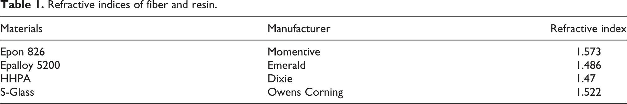
An S-glass woven fabric manufactured by BGF Industries is used as the fiber reinforcement in the transparent composites. The reinforcement consists of a bi-directional [0°/90°] 8-harness satin weave. The fabric has a weight of 303.5 g/m2 (8.95 oz/yd2) and thickness of 0.23 mm (0.009) in. The refractive index of the fibers is reported by BGF Industries to be approximately 1.522 (Table 1).
Refractive indices of fiber and resin.
Epoxy selection and synthesis
To synthesize a compatible resin with a matching refractive index equal to the fiber refractive index, a resin system needs to consist of at least two parts to tailor a refractive index based on the volume of each of the constituents. In order to maintain a stoichiometric balance between both epoxy and cure hardener, a second epoxy is introduced. The two epoxies chosen for the resin system are Epon 826 from Momentive Performance Materials and Epalloy 5200 from Emerald Performance Materials. The cure hardener selected for the resin system is hexahydrophthalic anhydride (HHPA) from Dixie Chemical. The refractive index of the liquid epoxies and cure hardener are shown in Table 1. A transparent catalyst is also utilized to initiate the chain growth but is ignored in regard to the refractive index due the minimal amount of catalyst needed compared to other constituents.
The synthesis of the resin consisted of varying the amount of the two epoxies to modify the refractive index of the resulting resin. All samples were composed of a constant amount of HHPA and catalyst. The HHPA was held constant according to a 1:1 stoichiometric balance between total epoxy and cure hardener. The total amount of epoxy was varied between 100% Epon 826 and 100% Epalloy 5200. Resins were manufactured with these epoxy ratios and narrowed incrementally until a refractive index was matched with the S-glass fibers. The refractive index is matched to the S-glass fibers by curing a small amount of a resin formulation and S-glass fibers in aluminum pans. The cure cycle of the resin system is a 110°C cure for 1 h and is further discussed in Section 3. Upon curing, the aluminum pans are peeled, and the resulting sample is inspected for visible fibers to determine refractive index matching. The resulting resin system is shown in Table 2.
Resin system.

Manufacturing
To manufacture the transparent composites from the S-glass fibers and epoxy resin system, the vacuum assisted resin transfer molding process (VARTM) was selected due to the ease of manufacture of the composite panels. The process is similar to a typical autoclave process in which the composite is manufactured under a sealed vacuum bag for the given cure cycle. The major difference of the two processes is lack of a pressurized atmosphere for the VARTM process. The VARTM process operates entirely at atmospheric pressure (101 kPa).
After preparation of the molds, four layers of the S-glass woven fabric are laid up in between the two molds as shown in Figure 1. Sealant tapes are positioned around the edges of the glass mirror mold and around the composite layup. The resin inlet is placed on the side of the fibers and the vacuum outlet is positioned farther away on the opposite side of the composite. Release fabric and breather fabric are used to connect the vacuum outlet to the edge of the layup. This is done to encourage a slow resin infiltration to maximize fiber wetting and to minimize the voids in the part. The glass square mold is placed directly on the fibers, and the glass mirror mold is prepared for infusion (Figure 2). A vacuum bag is applied, and a vacuum is connected to the layup before infusion to check for any leaks in the layup.
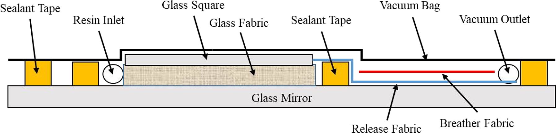
VARTM process schematic for transparent composites.
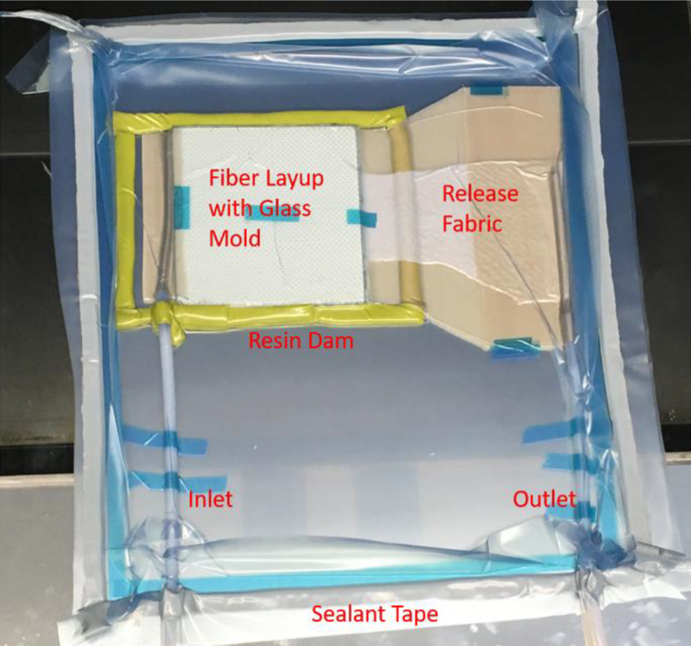
VARTM layup for infusion.
The infusion process for VARTM consists of applying a vacuum to the mold and heating both the layup and epoxy resin to 50°C. Once the resin system has fully reached 50°C, the inlet line is opened to allow the epoxy resin to flow into the layup. Throughout the entirety of the infusion, both the layup and resin are maintained at 50°C to keep a low resin viscosity. With the resin open to the atmosphere, the resin is pushed through the layup which is under vacuum. The resin flows from the inlet into the fibers and across the mold toward the outlet. Once the resin has fully infused the part, the inlet and outlet are sealed to prevent any air from entering the layup. The layup is then placed under the resin cure cycle of 110°C for 1 h (Figure 3). After curing, the transparent panel is examined for visible voids, microscopic voids, surface finish, and refractive index matching. If the sample contained few or no visible (non-microscopic) voids, the sample was cut and prepared for additional testing.

Transparent composite cure cycle.
Experimental methodology
Tension test specifications
All tension tests were conducted according to ASTM D3039-17 Standard Test Method for Tensile Properties of Polymer Matrix Composite Materials 14 and ASTM D638-14 Standard Test Method for Tensile Properties of Plastics. 15 Five composite samples are cut to approximate dimensions of 152.4 mm × 12.7 mm × 1.14 mm (6 in. × 0.5 in. × 0.045 in.). Neat resin samples are manufactured in a dog bone mold with test cross-section of 13.0 mm × 3.2 mm (0.5 in. × 0.125 in.) for tensile testing. Precise dimensions for each sample are recorded before each test. For the video extensometer, the gauge length is marked as two black dots approximately 1 in. apart on all samples (Figure 4). The tensions tests are conducted on an Instron 5985 universal testing machine with 10 kN load cell. Load and deflection are recorded along with strain from the video extensometer. Stress is determined after testing from load and sample dimensions.
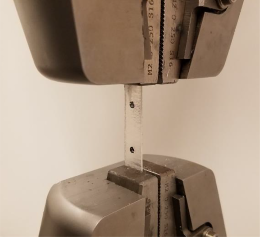
Tension test setup for transparent composites.
Flexure test specification
All flexure tests were conducted according to ASTM D7264-15 Standard Test Method for Flexural Properties of Polymer Matrix Composite Materials 16 and ASTM D6272-17e1 Standard Test Method for Flexural Properties of Unreinforced and Reinforced Plastics and Electrical Insulating Materials by Four-Point Bending. 17 The four-point bend test is used due to heterogeneous materials composing the composite. Four composite samples are cut to dimensions of 152.4 mm × 12.7 mm × 1.52 mm (6 in. × 0.5 in. × 0.06 in.). Five neat resin samples are cut to 76.2 mm × 12.7 mm × 3.0 mm (3 in. × 0.5 in. × 0.12 in.). In accordance with ASTM D7264, composite samples are tested with a 60:1 span-to-thickness ratio due to the thickness of the transparent panels so the four-point bend fixture was set to provide a support span of 91.44 mm (3.6 in.). The test speed is 1 mm/min calculated as

where R is test speed in mm/min, Z is rate of straining of the outer fiber (provided as 0.01 mm/mm/min), L is the span in mm, and d is the width of the beam in mm. The test setup is shown in Figure 5. Neat resin samples are tested in accordance with ASTM D6272 with a 16:1 span-to-thickness ratio. The four-point bend fixture support span was set to 40.5 mm (1.59 in.). The test speed is 1 mm/min calculated as

Four-point flexure test setup for transparent composites.

where R is test speed in mm/min, Z is rate of straining of the outer fiber (provided as 0.01 mm/mm/min), L is the span in mm, and d is the thickness of the beam in mm.
Impact test specifications
All impact tests were performed using ASTM D7136/D7136M-15 Standard Test Method for Measuring the Damage Resistance of a Fiber-Reinforced Polymer Matrix Composite to a Drop-Weight Impact Event. 18 Impact testing was conducted on an Instron Dynatup 9250 HV frame. The samples were impacted by a 6.435 kg drop weight with a 12.7 mm diameter impactor pin with a rounded tip. The drop height was adjusted to generate 2 and 5 J/mm impact forces. Samples were held during the impact tests by two clamping plates.
Results
Tension test results
All five tension samples were successfully tested. Of the five samples, four broke within the gauge section, and the fifth sample’s tensile modulus and strength were within the standard deviation of the other four samples. The tensile samples had a tensile modulus of 17.86 ± 1.32 GPa and tensile strength of 624.6 ± 32.8 MPa. The tensile stress-strain curves for the transparent composite samples are shown in Figure 6.
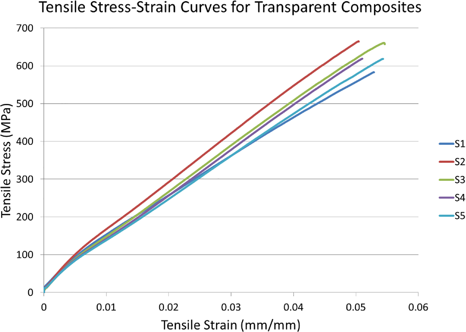
Tensile stress-strain curves for the transparent composite.
The five neat resin tension samples were also successfully tested. The neat resin tensile samples had a tensile modulus of 2.611 ± 0.074 GPa and the tensile strength was 27.31 ± 1.55 MPa. The tensile stress-strain curves for the neat resin samples are shown in Figure 7.

Tensile stress-strain curves for pure resin.
Flexure test results
All four flexure samples were successfully tested. The four samples did not fail, but the tests stopped due to the stagnation of the flexure stress with increasing strain. The flexural samples had a flexural modulus of 19.69 ± 1.23 GPa and flexural strength of 155.7 ± 3.8 MPa. Due to a low load (40 N) on a 10 kN load cell, the samples displayed some fluctuation in the values of flexural stress near the yield point. However, the results show a consistent value for both flexural modulus and strength. The neat resin flexural samples were tested until failure. The neat resin samples exhibited a flexural modulus of 6.303 ± 0.096 GPa and flexural strength of 154.6 ± 14.4 MPa.
Impact test results
Two identical plates (A and B) were prepared to supply six samples per energy level. Samples were hit with a nominal 2 and 5 J of energy and the reactions were recorded. The low energy impact had a peak load of 1.325 ± 0.103 kN. This generated an impact energy of 2.383 ± 0.018 J. The low energy impact produced some visible internal delaminations within the transparent plate (Figure 8 on left). The transparent composites absorbed 0.919 ± 0.341 J of energy (Figure 9). The results are compiled in Table 3.
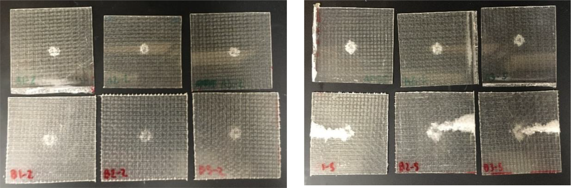
Samples after impact (2 J left, 5 J right; A top, B bottom).

Energy vs time for 2 J impact of transparent composites.
Impact results for 2 J impact test on transparent composite.

The high energy impact had a peak load of 2.084 ± 0.293 kN. This produced an impact energy of 5.639 ± 0.046 J. The high energy impact produced visible internal delaminations and cracks accompanied by some fiber breakage which was particularly evident within the B samples (Figure 8 on right). The average absorbed energy was 3.515 ± 1.081 J (Figure 10). The results are compiled in Table 4.

Energy vs time for 5 J impact of transparent composites.
Impact results for 5 J impact test on transparent composite.

Conclusions
An epoxy resin system was synthesized from epoxy systems Epon 826 and Epalloy 5200, and cure hardener HHPA. The resin system was tailored to match the refractive index of an S-glass woven fabric upon cure. VARTM layup was used to produce transparent composite panels by infusing the epoxy resin into an S-glass continuous fiber mat. The VARTM layups were then cured at 110°C for 1 h. Samples were examined for visual transparency upon curing. The panels were tested for tensile, flexural, and impact properties. The resulting tensile modulus was 17.86 ± 1.32 GPa with a tensile strength of 624.6 ± 32.8 MPa. The resulting flexural modulus was 19.69 ± 1.23 GPa, and the flexural strength was determined to be 155.7 ± 3.8 MPa. The impact behavior of the panels showed fair damage resistance with 0.919 ± 0.341 J of 2.383 ± 0.018 J impact energy absorbed and 3.515 ± 1.081 J of 5.639 ± 0.046 J of impact energy absorbed.
Supplemental Material
Supplemental Material, sj-pdf-1-ppc-10.1177_09673911211023031 - Development of fiber-reinforced transparent composites
Supplemental Material, sj-pdf-1-ppc-10.1177_09673911211023031 for Development of fiber-reinforced transparent composites by Robert Meinders, David Murphy, Gregory Taylor, K Chandrashekhara and Thomas Schuman in Polymers and Polymer Composites
Supplemental Material
Supplemental Material, sj-pdf-2-ppc-10.1177_09673911211023031 - Development of fiber-reinforced transparent composites
Supplemental Material, sj-pdf-2-ppc-10.1177_09673911211023031 for Development of fiber-reinforced transparent composites by Robert Meinders, David Murphy, Gregory Taylor, K Chandrashekhara and Thomas Schuman in Polymers and Polymer Composites
Supplemental Material
Supplemental Material, sj-pdf-3-ppc-10.1177_09673911211023031 - Development of fiber-reinforced transparent composites
Supplemental Material, sj-pdf-3-ppc-10.1177_09673911211023031 for Development of fiber-reinforced transparent composites by Robert Meinders, David Murphy, Gregory Taylor, K Chandrashekhara and Thomas Schuman in Polymers and Polymer Composites
Footnotes
Declaration of conflicting interests
The author(s) declared no potential conflicts of interest with respect to the research, authorship, and/or publication of this article.
Funding
The author(s) received no financial support for the research, authorship, and/or publication of this article.
References
Supplementary Material
Please find the following supplemental material available below.
For Open Access articles published under a Creative Commons License, all supplemental material carries the same license as the article it is associated with.
For non-Open Access articles published, all supplemental material carries a non-exclusive license, and permission requests for re-use of supplemental material or any part of supplemental material shall be sent directly to the copyright owner as specified in the copyright notice associated with the article.