
Abstract
A centrifugal mixing method was developed to disperse ceramic particles inside a thermosetting polymer. Horizontal centrifugal equipment was used to fabricate cylindrical rods from epoxy reinforced with silicon carbide particles. Silicon carbide particles (SiC) are used for the outer coating of epoxy to increase wear resistance. In the centrifugal mixing process, there are three important variables: rotational speed, ceramic percentage and, ceramic size which affect ceramic particle distribution. This paper aims to find the relationship between these variables and the distribution of ceramic particles then determine the optimum conditions to get maximum wear resistance and hardness. From the experiment and analysis, it can be concluded that when mixing speed was greater than 600 rpm, the possibility of air bubbles formation was increased especially for ultrafine particles. Otherwise, the maximum wear resistance and hardness values were found in ultrafine size SiC samples reinforced with 30 wt% which were mixed at a low speed of 300 rpm.
Introduction
The rapid growth in industrial applications leads to increased demand for new material. Polymer composites can be an excellent alternative to meet that growing need, for their excellent characteristics. However, polymers are subject to wear especially in the contact area outer surface such as biomedical joint, so the need has increased to improve the outer surface of polymers to increase the wear resistance and hardness. Wear resistance surface and coating thickness have attracted much attention due to the extensive variety of modern applications.1-3 There are different techniques applied to the material to improve the wear resistance property, such as using lubricating film; Making the wearing surface hard; Making the wearing surface resistant to fracture or to corrosion; to fatigue. Ceramic materials can provide superior properties such as corrosion resistance and high hardness for the original base metal. 4 Today, silicon carbide (SiC), alumina (Al2O3) and zirconia (CZ) based ceramics have the highest industrial applications. 5 Ceramic surfaces can be successfully produced on several different substrates, many of the fabrication operations are complicated and not appropriate for quick, huge scale manufacture. 6 Furthermore, these surfaces can be corrupted or harmed rapidly under severe situations because of the ingrained properties in low surface energy organic material.7,8 Epoxies were made by polymerizing a mixture of two compounds (resin and hardener) with a specified amount. At this point, the curing is started to produce hard material. 9 Epoxy resins have good mechanical properties, epoxy resins have a poor wear resistance. 10 Silicon carbide particles were used to improve the wear resistance of epoxies by several researchers. Basavarajappa and Ellangovan 11 studied dry sliding wear characteristics of glass/epoxy composite filled with graphite and silicon carbide particles and concluded that applied load has much more effect comparing with sliding distance. Chauhan et al. 12 studied the tribological performance of Vinyl Ester composite under different wear sliding conditions. The researchers reported that SiC reinforcement improves the wear behaviour in all conditions. Formisano et al. 13 found that wear resistance improves with the increases in the dimensions and the content of the filling particles. Rong et al. 14 found that the small filler content of nano-sized SiC reduced the wear rate and friction coefficient of epoxy even under severe conditions. Mohan et al. 15 reported that the wear resistance of SiC filled glass epoxy composites decreases with a decrease in applied load and in temperature. Suresha et al. 16 investigated the wear behaviour of SiC filled glass-epoxy composites. The results of their investigation showed a promising trend for the SiC/epoxy composites. For the excellent properties of SiC, it has been chosen for the present investigation. One of the conventional mixing techniques is centrifugal mixing, which is used to obtain the cylindrical parts.
Centrifugal casting has two types according to axis rotation: horizontal type and vertical type. In the vertical type, the rotation happens about a vertical axis, and in the horizontal types, the rotation happens about horizontal axis. 17 Centrifugal mixing is a suitable method for casting Functionally Graded Materials (FGMs). 18 Functionally graded casting is used to cast composites with different densities in different phases. 19 Anyway, there are no researches emphasizing the assumption that centrifugal mixing can be effectively used for obtaining outer layer for the cylindrical bodies. In this paper, the centrifugal technique was used to produce a polymer rod with hard ceramic content. Furthermore, the present work has been undertaken to study effect of the ceramic content over wear resistance behaviour and hardness values of the epoxy.
Experimental methods
Materials
The polymer used in the investigation is a Kemapoxy 150 JM, its density at room temperature is 1.15 ± 0.02 kg/l, supplied from Modern Chemicals for Modern Building, Egypt. The fillers used were silicon carbide particles obtained from Sigma Aldrich, Germany. Its particle size is less than 25 µm and the ultrafine particles are less than 90 nm.
Method
The outer hard layer was produced by a centrifugal mixer apparatus (Figure 1). In this apparatus, a plastic tube (20 ml size) was filled with a mixture from the matrix and ceramic powder to produce the samples. This tube was placed inside a special Teflon container attached to the pulley, which gets its rotation from the AC motor, by rotating this tube with a speed proportional to horizontal axis speed. The gravitational force produced by horizontal axis spinning was used to distribute the ceramic powder inside the epoxy to produce the uniform ceramic outer layer. The centrifugal mixer apparatus was designed and built to perform the required tests. The mixer was equipped with an inverter drive (ATV45075N Altivar 5) to control the motor rotational speed in the range of 0–1500 rpm. Figure 2 shows a description of the techniques used in the investigation. The Sample obtained by using the horizontal centrifugal mixer was cylindrically rod as shown in Figure 3 with 130 mm length and 15 mm diameter.

Horizontal centrifugal mixer apparatus used in the investigation: (1) inverter, (2) AC motor, (3) sample holder and (4) test tube.

Sequence of steps to prepare samples.
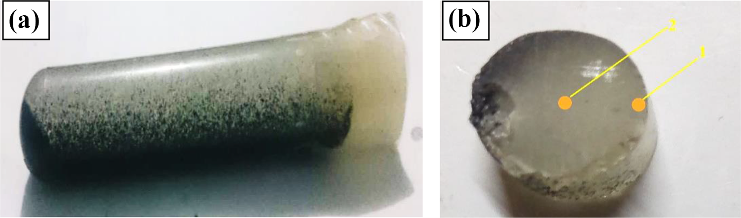
Obtained sample with the horizontal centrifugal mixer: (a) side view and (b) top view (Red arrows refer to locations of the microstructure study).
Mechanical properties
The effects of different parameters on mechanical properties including weight percentage and size of SiC were investigated under 300, 600 and 900 rpm of rotor speed. Then the samples were cut using a cutter machine in directions parallel to the solidification direction. Each cross-section was polished with an emery paper and examined under an optical microscope. The ceramic distribution was studied in the cross-section perpendicular to the solidification direction using an image analyser (Image Pro Plus; Media Cybernetics Co., USA). Microstructure photomicrographs were taken at two locations as shown in Figure 3(b).
The hardness Shore D type was measured according to the standard CSN EN ISO 868. All lengths of test specimens were 5 mm. Wear behaviour of the obtained samples were conducted using a pin on disc wear testing apparatus under various loads and rotating speeds after 100 m distance at room temperature for the outer surface of the sample. The device was described previously in the work of Sharma et al. 20 In the test, the flat end of cylindrical samples (13 mm in diameter and 90 mm in length) were weighed before the test and after it to calculate losses on the weight. Then wear rate calculated by the following equation. 21

Where,

Results and discussion
Microstructure
SEM photomicrographs were used to confirm the dispersion of the particles inside the matrix. Figures 4 and 5 show the microstructure photomicrographs and the particle size distributions for the two locations at different conditions. It is clear from the figure that the SiC particles in the micro and in the ultrafine size are completely dispersed inside the epoxy, and the maximum number of particles were on the outer surface (location no. 1) .The figures show also that a huge amount of ceramic coating was found on the outer surface. It can be observed also from photomicrographs that SiC particles flow towards the outer layer due to the action of centrifugal force. As shown in Figure 5(a), a small number of microparticles are observed at the centre (location no. 2). Also, an appreciable concentration of particles was taking place in the outer surface (location no. 1). The other major observation in the SEM photomicrographs is the presence of a large amount of SiC particles ultrafine size without making any agglomeration at the outer surface (Figure 4(c)). This enhancement may be due to that the SiC particle’s density is higher than the epoxy, which makes the particles move towards the outer layer. On the other hand, the ultrafine particles do not have the tendency to concentrate, this is due to the small particles having higher terminal velocity compared with the large size particles and the fluid velocity. 22 In addition to that, the ultrafine size of SiC has a much larger surface to weight ratio for large particles which leads to an increase in the surface free energy.

SEM photomicrograph of cross-section (30 wt% and 600 rpm) at different size in location 1: (a) micro size, (b) ultrafine sizes and (c) A mixture of ultrafine and micro sizes.

SEM photomicrograph of cross-section (30 wt% and 600 rpm) at different size in location 2: (a) micro size, (b) ultrafine sizes and (c) mixed of ultrafine and micro sizes.
Hardness measurement
Hardness was measured on the outer surface at different conditions. Hardness values for all samples are shown in Figure 6, values are the average of three readings. The largest hardness values have been found for ultrafine size samples. The hardness measured at 300, 600 and 900 rpm showed an average hardness of 79 (Shore D), the results show that the hardness decreases with decreasing weight fraction of ceramic particles from 30 wt% to 10 wt%. However, the ceramic size shows a lower increase in hardness compared with SiC weight fraction. At 10 wt% SiC and 300 rpm, the hardness values were 68, 66 and 63 for ultrafine, ultrafine/micro and micro size, respectively. It can be noticed that the hardness values increase with increasing the mixing speed. This enhancement may be due to the structural alterations as a result of the increase in the speed of mixing. 21

Hardness values versus mixing speed at different wt% of sic: (a) ultrafine size SiC, (b) mixed of ultrafine and micro size SiC and (c) micro size SiC.
Wear rate
Figures 7 to 9 presented wear rate results at different loads for the samples with different content and size of SiC. It has been found that the wear resistance of all samples was improved by using the ceramic particles. This can be related to the fact that the hard outer layer protects the surface from severe contact. The results illustrated also, that the wear rate of the sample decreases when increasing the weight % of SiC and the size of the ceramic. This due to the epoxy can easily remove at the contact area but in the composite case the SiC particles act as a rough surface compared to the counter surface against which they slide. Many researchers14,23–25 had shown the effect of the weight percentage on the wear rate of the composites. They proved that the wear rate decreases with the increasing of the weight percentage of the SiC particles.

Effect of load on wear rate for ultrafine size at mixing speed: (a) 300 rpm, (b) 600 rpm and (c) 900 rpm.

Effect of load on wear rate for mixtures of ultrafine and micro sizes at mixing speed: (a) 300 rpm, (b) 600 rpm and (c) 900 rpm.
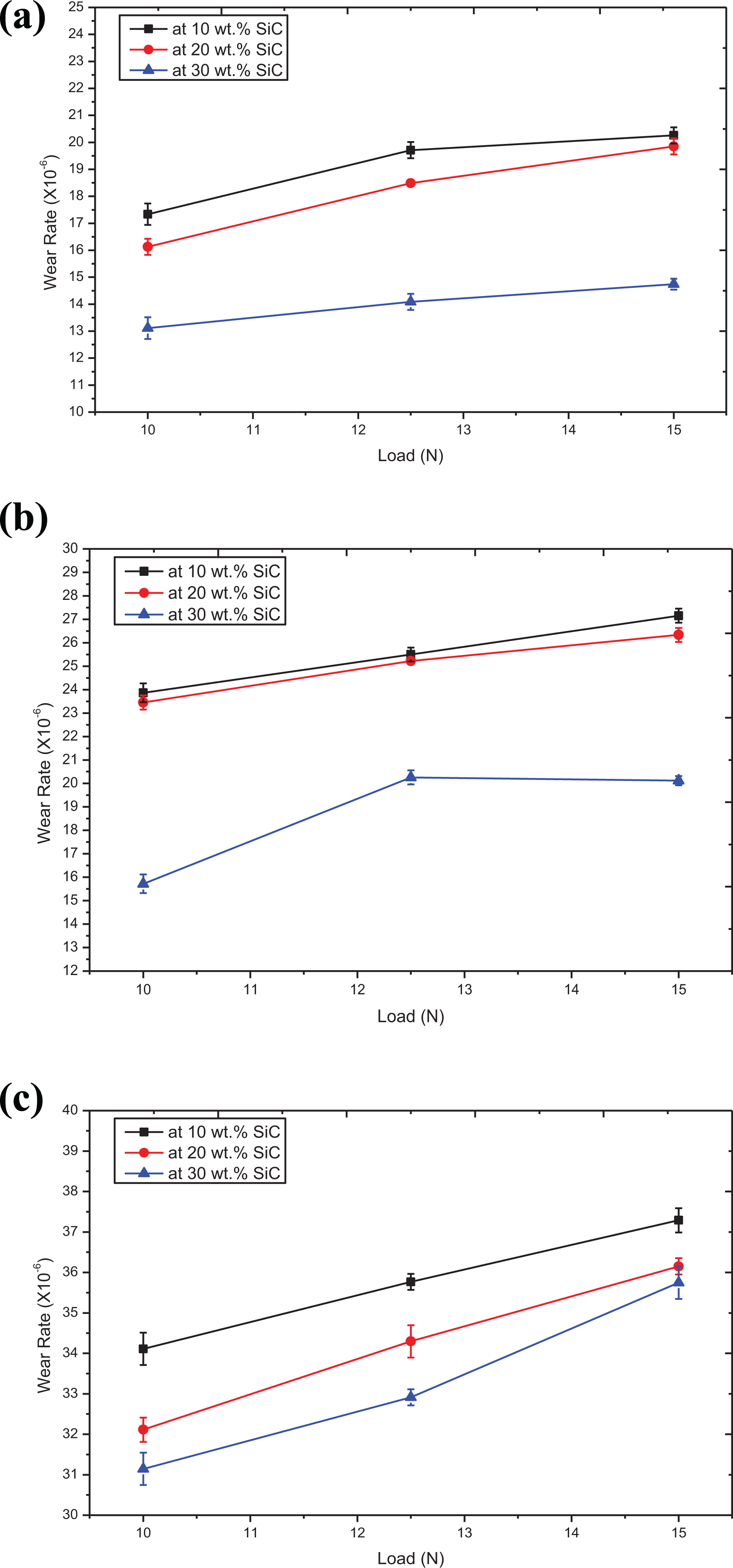
Effect of load on wear rate for micro size at mixing speed: (a) 300 rpm, (b) 600 rpm and (c) 900 rpm.
Maximum wear rate values were found in the micro size samples, the results show also that wear resistance enhanced at low mixing speed. The range of wear rate results at 10 wt% of SiC and mixing speed 900 RPM were varying from 31.14 × 10⁻⁶ to 32.74 × 10⁻⁶ at 10 N, from 32.91 × 10⁻⁶ to 35.76 × 10⁻⁶ at 12.5 N and 35.74 × 10⁻⁶ to 37.28 × 10⁻⁶ SiC at 15 N. In other words, about 4% enhancement in wear resistance of composite samples at 15 N caused by the SiC existent, higher SiC concentrations can produce significant effects. Therefore, the addition of the hard ceramic makes the outer surface of epoxy harder. Enhancement in wear resistance at higher wt% of SiC concentrations is due to the perfect distribution of SiC particles because they boost the resistance to abrasion. However, wear rate increases for all samples with the increasing in load which increases friction and abrasion on the outer surface of the composite. Increasing in the wear rate at high mixing speed was happened due to air bubbles formed inside the composite, these bubbles reduce the bonding power between particles and epoxy. In general, during the sliding process, the material is transferred from the sample to the surface of the steel disc, and the transferred material is covering the abutting surface with a thin and uniform film, which helps reduce friction and wear of the composite epoxy.
Worn surface morphology
To study the wear mechanism for composites filled with different amounts of SiC particles, the worn surfaces of samples were examined using scanning electron microscope SEM. The effects of the SiC content on the wear rate of epoxy composites can be explained as follows: The epoxy with no amounts of SiC particles behaved as a brittle material and the cracks were perpendicular to the direction of sliding. So, material waves were formed, and debris created (Figure 10(a)). On the other hand, epoxy with the content of SiC particles leads to waves finer compared with the waves generated in the pure epoxy (Figure 10(b)). In the case of uniform distribution of SiC particles (10, 20 and 30 wt%), the generation of the cracks into the composite samples were hindered by the ceramic particles on the surface. Cracks and grooves on the wear surface refer to a severe abrasive wear mechanism, in case of the low content of SiC particles (Figure 11(a) and (b)). As a result of weak bonding between particles and resin and voids formation due to high mixing speeds (600 and 900 rpm). Increasing the amount of SiC to 30 wt% of the ultrafine particles, mixing with low speed (300 rpm) and well distribution of particles on the wear surface, leads to the following: – Increasing the contact area between the wear pin and the hard particle, and – reduce the possibility of voids in the surface.

Wear mechanism: (a) wave development on wear surface of the low amounts of sic particles and (b) finer wave on the wear surface of the uniform content of ceramic particles.
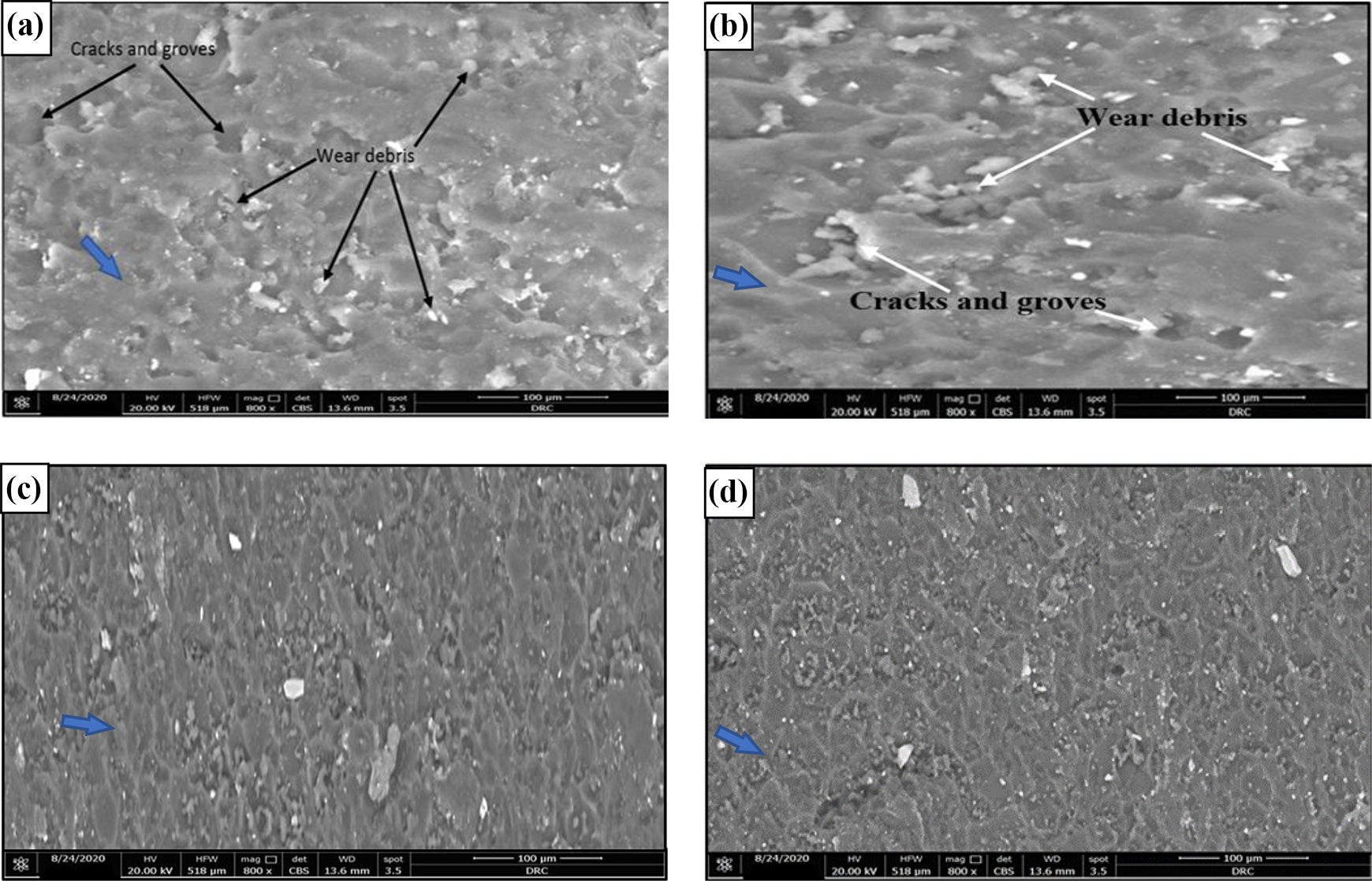
SEM photomicrograph of worn surface at: (a) 10 wt% and 900 rpm (micro size), (b) 10 wt% and 900 rpm (ultrafine and micro sizes), (c) 20 wt% and 600 rpm ultrafine size and (d) 30 wt% and 300 rpm ultrafine size. Note: Blue arrow refers to the sliding direction.
So, the surface refers to a mild abrasive wear mechanism, due to the high wear resistance of the composite sample.
Figure 11(c) and (d) show SEM photomicrograph at high wear resistance. It is clearly shown that SiC content helps in producing smooth wear surface, this is due to the good dispersion for ultrafine SiC inside the epoxy resin (Figure 11(d)). As a result, the epoxy composite material shows better wear resistance than the epoxy resin reinforced with a small amount of SiC particles (Figure 11(a) to (c)). Also, these results can be due to the difference in bonding power between SiC particles and epoxy matrix at each mixing case.26,27
General comments
Mixing with low speed (300 rpm) gives higher hardness and higher wear resistance as compared to mix with high speed (900 rpm) may be to the following reasons: the strength of the ‘weak, reversible’ crosslinks will be influence with mixing speed. 28 Also, the air bobbles and coarse aggregate content will be affected by mixing speed. At low mixing speed cross-link densities become very high, therefore the polymer composite become very rigid or glassy. 29 Ultrafine particles showed higher wear resistance as compared with micro size, this improvement may be due to the excellent distribution for ceramic particles and voids absences as shown in the microstructure study.
Conclusions
Ceramic coatings with different wt% and size of SiC and mixing at different speeds were successfully fabricated by horizontal centrifugal mixer. Analysis of their mechanical properties and microstructure has led to the following conclusions Microstructure study shows that the ceramic particles with all sizes are uniformly distributed in the outer surface of epoxy matrix for all selected mixing speeds. SiC particles as micro and as ultrafine size were completely dispersed inside outer surface of epoxy but, they failed in reaching to the inner surface specially at low mixing speed. which makes this method is suitable to enhance the outer surface of polymer and suitable to produce low weight product with hard outer surface. Hardness increases with 5% with the increasing in weight fraction of ceramic from 10 wt% to 30 wt%. Hardness decreases with 12% with the increasing in mixing speed from 300 to 900 rpm. Wear rate increases up to 75% for all samples with the increasing in load from 10 N to 15 N and decreases with 17% when increasing the wt% of SiC from 10 wt% to 30 wt%. and when decreasing the size of the ceramic. Wear resistance decreases with 15% in the micro size compared with the ultrafine size of SiC.
Footnotes
Declaration of conflicting interests
The author(s) declared no potential conflicts of interest with respect to the research, authorship, and/or publication of this article.
Funding
The author(s) received no financial support for the research, authorship, and/or publication of this article.