
Abstract
The present work verified the capability of a solid state self-healing system for retarding or arresting fatigue cracks in epoxy materials subjected to cyclic loading at room temperature. A solid state self-healing material is demonstrated using a thermosetting epoxy polymer which was modified by incorporating a linear thermoplastic polydiglycidyl ether bisphenol-A (PDGEBA) as a healing agent. The stress-controlled constant amplitude (CA) tensile fatigue behavior at stress ratio, R = 0.1 and frequency 10 Hz for both the neat and the modified epoxy was investigated. Fatigue life and residual strength degradation were continuously monitored during the fatigue tests. The modified epoxy fatigue life was shown to be increased by ∼50% after healing periods. The fatigue-healing process was proven through the surface and cross-section resin morphology analyses using microscopy optic and scanning electron microscope (SEM). On the whole, the solid state self-healing system has proven to be very effective in obstructing fatigue crack propagation, effectively improved the self-healing polymeric material to achieve higher endurance limits.
Introduction
Fatigue and fatigue failure are critical for polymeric materials used in structural applications. Fatigue and the associated slow accumulation of damage and deterioration in performance plague all materials, particularly those that fail in a brittle manner. Therefore, imparting self-healing capability to polymers and polymer composites is an effective way to solve the problem.1-3 The concept of self-healing polymeric materials was proposed as a means of healing invisible micro-cracks. 4 This self-healing concept or basic mechanism has been inspired from biological systems.5,6 Intrinsic systems of self-healing materials possess a latent self-healing functionality that is triggered by damage or by an external stimulus; i.e. heat or intense photo illumination.7-9 These materials rely on chain mobility and entanglement, reversible polymerizations, melting of thermoplastic phases, hydrogen bonding, or ionic interactions to initiate self-healing.10-12 Because each of these reactions is reversible, multiple healing events are possible.
A solid state healable system was identified as an alternative technology for the intrinsic self-healing system.13-16 This system employs a thermosetting resin as a matrix of which a thermoplastic is dissolved. The efficiency of healing damage was examined through impact and compact tension tests. Upon healing a fractured resin system, the thermoplastic materials can become mobile above a particular temperature and diffuse throughout the thermosetting matrix. Some chains bridging closed cracks and thereby facilitating healing. These intrinsic healing mechanisms are thermally reversible for multiple healing events; even upon damage at the same site, and able to heal the cracks of different sizes and shapes (limited to small damage volumes).7,8,10
Characterization of fatigue response is more complex than monotonic fracture because it depends on several factors such as the applied stress intensity range, the loading frequency, the ratio of applied stress intensity, the healing kinetics, and the rest periods employed.17,18 So far, only a few papers of healing of fatigue failure have been reported in the literature for polymeric materials. Earlier studies have shown that imparting self-healing capability to polymers and polymer composites leading to the retardation or permanent arrest of further fatigue crack propagation.19,20
Daniel and Kim 21 investigated fatigue damage in asphalt by evaluating the changes in the stiffness gain under high temperatures during the rest period. Hamilton et al. 17 studied the fatigue response of an epoxy matrix containing vasculature for the delivery of liquid healing agents. Fatigue crack growth in an epoxy matrix was impeded by infiltrating the cracks with liquid healing agents via a simple vascular system consisting of two micro-channels and external pumps. Meanwhile, Sang et al. 22 demonstrated a fatigue loading response toward self-healing laminate composites based on polyurethane/poly (urea-formaldehyde) microencapsulated healing agents. Self-healing for 24 h at room temperature led to 52.4% recovery of Young’s modulus after 15,000 fatigue cycles; which was 2.7 times higher compared to control composites, which led to higher endurance limit and life extension, or even complete arrest of cracking. Kostopoulos et al. 23 investigated a novel self-healing carbon/epoxy composite based on the Diels–Alder reaction mechanism in critical regions. The activation of the healing functionality of self-healing composites at a certain number of fatigue cycles significantly extends their fatigue life of about 75%. Also, Yuan et al. 20 work verified the capability of epoxy/mercaptan/tertiary amine system for retarding and/or arresting fatigue cracks in epoxy materials via manual infiltration. The effects of hydrodynamic pressure crack tip shielding, polymeric wedge and adhesive bonding of the healing agent were revealed.
Although some fatigue crack propagation studies have been undertaken on autonomic systems, studies on the cyclic fatigue response toward non-autonomic systems are limited. Hence, the main aim of this investigation was to study the response of solid state self-healing material toward fatigue failure.
Experimental procedures
Materials and specimen fabrication
The healing matrix system was produced using a base thermosetting resin consisting of diglycidyl ether of bisphenol-A (DGEBA) with

The chemical structure of (a) repeat unit resin (from the curing of the anhydride (NMA) with the epoxy (DGEBA) under catalyst) and (b) PDGEBA (healing agent) with glycidyl end-caps.
The modified resin or the solid state self-healing resin was prepared by adding a thermoplastic material (act as a healing agent (HA)) to this blend that was selected to be closely compatible with the main constituent, diglycidyl ether of bisphenol-A based resin.
13
The selected thermoplastic was poly(bisphenol-A-co-epichlorohydrin) (PDGEBA) with
Mechanical testing and characterization
There were two types of tests conducted in this study; namely, the tensile test and fatigue test. The tensile tests were performed to determine the tensile properties of the material, namely, the ultimate tensile stress and Young’s modulus, which were then used to design the fatigue test of the same material.
Tensile test
The tensile properties of the bulk epoxies were determined according to ASTM-D638 24 and ASTM-D3479M 25 test standard specifications, respectively. The schematic diagram showing the dimensions of the tensile test specimen is shown in Figure 2. All the tensile tests were performed using a 100 kN computer-controlled screw-driven test machine, with a constant crosshead speed of 1 mm/min. Five replicate tests were conducted for each material with the average tensile properties determined for all materials.
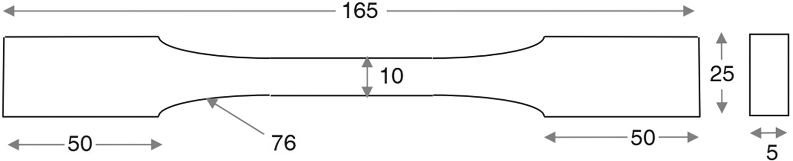
Schematic diagram showing the dimensions of the tensile and fatigue test specimens of bulk epoxy polymer.
Fatigue test
The fatigue test specimens were prepared with the same specific dimension as shown in Figure 2. The sharp edges of the bulk epoxy test specimens were smoothed with emery paper, before testing, to avoid any stress concentration effects. All the fatigue tests were performed according to the ASTM-D3479M 25 test standard specifications, using a 25 kN computer-controlled servo-hydraulic test machine (Instron 8874). The tests were run at constant load amplitude (CA). A sinusoidal waveform of frequency 10 Hz was applied with stress (S) ratio, R, of 0.1 (R = Smin/Smax, where Smin and Smax denote the minimum and maximum values of the cyclic stress intensity, respectively) (Figure 3a). The tests were carried out with 50% of the ultimate tensile strength (UTS) of the material as a maximum stress level, Smax. The strain was not monitored during the fatigue testing. Each loading condition was investigated with continuous cyclic loading to specimen failure and/or with a rest period to allow for healing (Figure 3b).

Schematic of (a) fatigue life test under fatigue loading parameter (frequency 10Hz, R = 0.1) with (b) the healing or rest period for each 600 cycles.
The tensile fatigue test was carried out both on the neat and modified epoxy resin. The test involved two loading tests. For the first test, both neat and modified epoxy resin specimen were subjected to the loading. In order to establish the S–N curves, the tests were carried out until the specimen failed (complete fracture) or were terminated at two million cycles whichever occurred first. Then, the second loading test involved only modified epoxy resin. In this case, modified epoxy resin was cyclic loading until the number of cycles was about 600. Then, the specimen was taken out to be repaired by heating in a circulating air oven at 160°C for 6 hours. Samples were repeatedly healed and tested throughout the study, to examine the effect of repeated healings on the efficiency of impact strength recovery. Each sample was tested three times, making a total of nine tests at each healing temperature. All the fatigue tensile tests were carried out at room temperature. During the fatigue tests, the maximum load, the minimum load, the mean load and the load amplitude as well as the number of cycles were monitored. The final data collected from fatigue tests were the number of cycles to failure for each specimen, which was recorded by a computerized data acquisition system.
Infrared spectroscopy analysis (FTIR-ATR)
Fourier transform infrared (FTIR) spectroscopy used in this study is the Spectrum ASCII PEDS 400 ATR Spectrometer from Perkin Elmer. The spectra were recorded at room temperature with an average signal of 64 scans at intervals of 2 cm−1 and 16 cm−1 resolutions in the 4000–500 cm−1 infrared spectrum.
Dynamic mechanical thermal analysis (DMTA)
DMTA was performed on a TA Instruments Thermal Analysis DMA 2980 operating in the single cantilever-bending mode at an oscillation frequency of 1 Hz with sample dimensions 35 mm × 15 mm × 5 mm. Data were collected from room temperature to 180°C at a scanning rate of 2°C/min.
Microscopy imaging
Surface morphological studies and cracking processes of resin matrix were performed using Optical Microscope. The microscope model used is the Axiolab A450909 and the magnification used is 5× and 10×. The cross-sectional fracture surfaces from the fatigue tests of the bulk epoxy specimens were examined using a scanning electron microscope (SEM). The fracture surfaces were first sputter-coated with a thin layer of gold, to prevent charging. Conventional secondary electron imaging conditions, with an accelerating voltage of 15 kV, were employed.
Results and discussion
Application on solid state self-healing system on fatigue crack propagation is an innovative step to prevent failure due to fatigue cracks in the structure of the polymer composite. Characterization of the response to the load fatigue is more complex than monotonic crack due to the dependence of the specimen to several factors such as the range of stress intensity which is used, the frequency of the load, the ratio of the intensity of the stress applied, the kinetic recovery, and recovery time that is used.2,3 Characterization of the neat and modified resin (with the PDGEBA healing agent) response on tensile fatigue loads was performed using fatigue life parameters, Nf and static strength residues.
Compatibility of healing agent and resin
The selection of healing agent and resin is critical in ensuring the production of homogeneous resin mixtures with the ability to undergo the self-healing process and thus improve the material lifecycle. The solubility parameter (δ) is an important parameter for predicting the compatibility of linear polymers (healing agent) with an epoxy resin system. Hoy’s method for the calculation of solubility parameters is determined from the number of components of molecular interaction which contribute to the cohesive energy.
26
This method takes all polar, dipole, and hydrogen bonding effects into consideration for the calculation of the total solubility parameter (δt) as shown in

where δd (dipole δ), δp (polar δ), δh (hydrogen δ) are the dipole, polar, and hydrogen bonding contributions to the solubility parameter.
The Hoy Solubility Parameter Software (from Computer Chemistry Consultancy, Germany) was used to simplify the calculation of solubility parameters using Hoy’s method. 27 As result, NMA with a solubility parameter of 31.77 (J/cm31/2 reacted with DGEBA monomer, whose value of solubility parameter is 22.04 (J/cm31/2, produced a polymeric matrix resin (Figure 1a) with repeat unit with a value of 21.88 (J/cm31/2. This value is close to the solubility parameter value of 21.25 (J/cm31/2 for the proposed healing agent (Figure 1b). Therefore, the linear polymer of PDGEBA has the potential to be soluble in most of the cured epoxy resins of a similar structure for healing. A small difference between the solubility parameters means that the intermolecular attractions between molecules of these two components are similar. Matching the solubility parameters should ensure that the healing agent is intermediately bonded to the matrix yet becomes mobile once the hydrogen bonds are thermally broken. This causes the healing efficiency to increase.
DMTA analysis was conducted to examine the effect of the healing agent (PDGEBA) in the resin system on the thermomechanical properties. From Figure 4, in agreement with the result of the solubility parameter, there is no significant change in glass transition temperature (Tg) and modulus with the addition of a healing agent into the control resin systems.
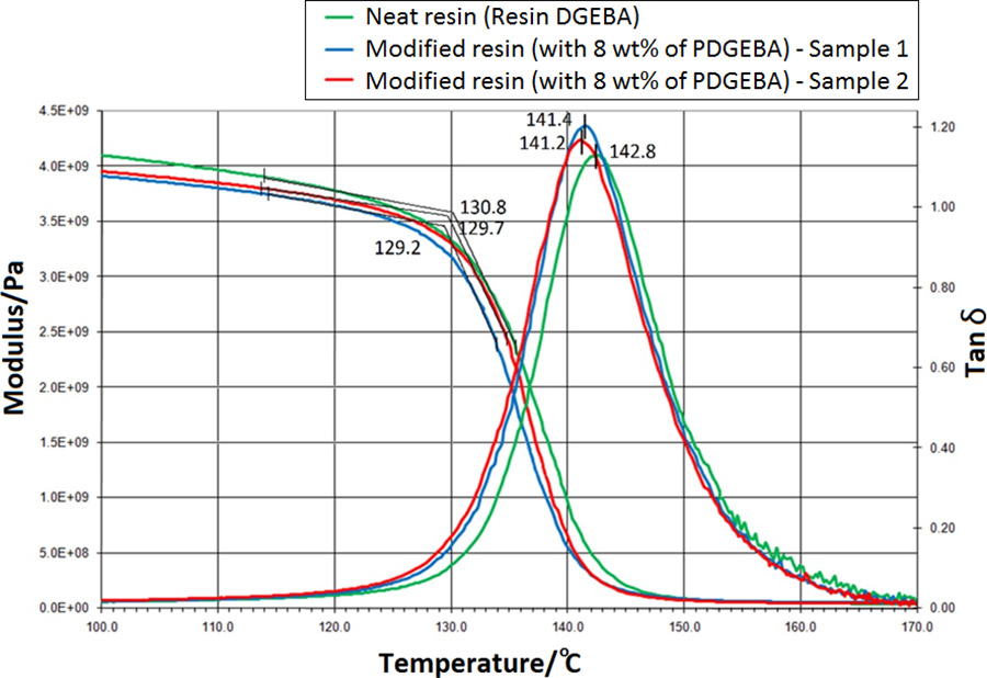
(a) DMTA (Tan δ and storage modulus (E’) scan for the control and healable resin with 8 wt% of HA between a temperatures range of 100°C to 170°C.
Furthermore, Tg from the maximum value of Tan δ has been used as a reference for the healing process. Based on this result, a temperature of 160°C is chosen for the healing process which is near/ higher than the Tg of the control/ neat resin; in which the transition in the amorphous regions (from the semi-crystalline solid resin) between the glassy and rubbery state occurs. At this temperature portions of the molecules would simply absorb the energy by momentarily deforming or stretching and can improve its flexibility. It is postulated that this effect can improve the diffusion of healing agents through the reptation process within the matrix resin.
Test strain
The static tensile test was carried out to obtain the maximum or ultimate tensile strength (UTS) which in turn will be used as a parameter in determining the value of the maximum stress in the fatigue test load. This is because of the sluggishness involving material damage when subjected to cyclic loading stress on the lower level of the ultimate static strength.17,20 The stress–strain curves for the epoxy specimens were shown in Figure 5. The average value of the UTS of the neat (control) and modified resin (with 8 wt% of healing agents PDGEBA) obtained from static tensile test are 38.2 and 39.6 MPa. Again, with the addition of a healing agent on the resin system, there is no significant difference in the results from the tensile test and this corresponds to the DMTA results. The maximum tensile strength (Smax) with 50% of the average UTS was used for the fatigue test for control and modified resin. Maximum stress values (Smax) are 19.1 and 19.8 MPa, respectively (Figure 5).

The stress–strain curve of (a) neat and (b) modified epoxy (with 8 wt% of healing agents PDGEBA).
Fatigue life evaluation
Typically, material fatigue performance is characterized by the change in either the life cycle (number of cycles until the material fails) or crack growth. Although the parameters of crack growth are suitable for quantitative analysis of mechanical cracking, the number of life cycles remains important in engineering applications. This is related to the life expectancy of all components that starts with the specimen in good condition before it experiences a micro-fracture that began under cyclic loading and subsequently spreads to form a macro fracture that ultimately leads to failure.20,22 Fatigue life (Nf) of material is defined as the total number of stress cycles required to cause failure to occur. Figure 6 shows the result of the cycle of failure, Nf for the neat and modified resin by graphing changes in force, Fmin against the number of cycles, N. The number of cycles that have been obtained are summarized in Table 1.

Graph of change in force (Fmin) versus number of fatigue cycles (N) for the neat and modified resin; with and without healing process.
Summary data for the number of cycles of fatigue testing required until the material fails.

Based on the total number of fatigue cycles obtained, it is clear that the fatigue life of the resin applied with five times the recovery process exceeds half (or 50%) of the fatigue life of the control resin (without the recovery agent). The results obtained indicate that the fatigue life of the resin matrix with the solid state self-healing system is longer compared to the epoxy resin matrix without the solid state recovery system.
A solid state self-healing system can be achieved by incorporating a compatible linear polymer in the thermoset or network matrix resin.13,14 This crack healing process was described schematically as shown in Figure 7. The healing agent should be reversibly bonded (e.g., through hydrogen bonding) to the cross-linked epoxy resin. Upon heating at the minimum healing temperature, the linear polymer is released to diffuse through the network of the cracked surface. The results obtained were in agreement with the concept of intermolecular diffusion of dangling chains or chain slippage. Aradian et al. 28 reported on the theory of crack healing via molecular inter-diffusion in polymeric materials involving the processes of surface rearrangement, wetting, diffusion and randomization that took place across the micro-fine crack. They also proposed a reptation model in which an interface was formed by random walk chains diffusing by reputation across a polymer–polymer weld line before the chains form new physical cross-links in which the interface strength was increased. These crack healing systems are time and temperature dependent and occur via the free volume, void closure, surface interaction and molecular entanglement between the damaged faces. In addition, the “dangling chains” concept is described as chain segments where one end is not connected to the network and exhibits a segmental inter-diffusion for micro-crack recovery.6,8
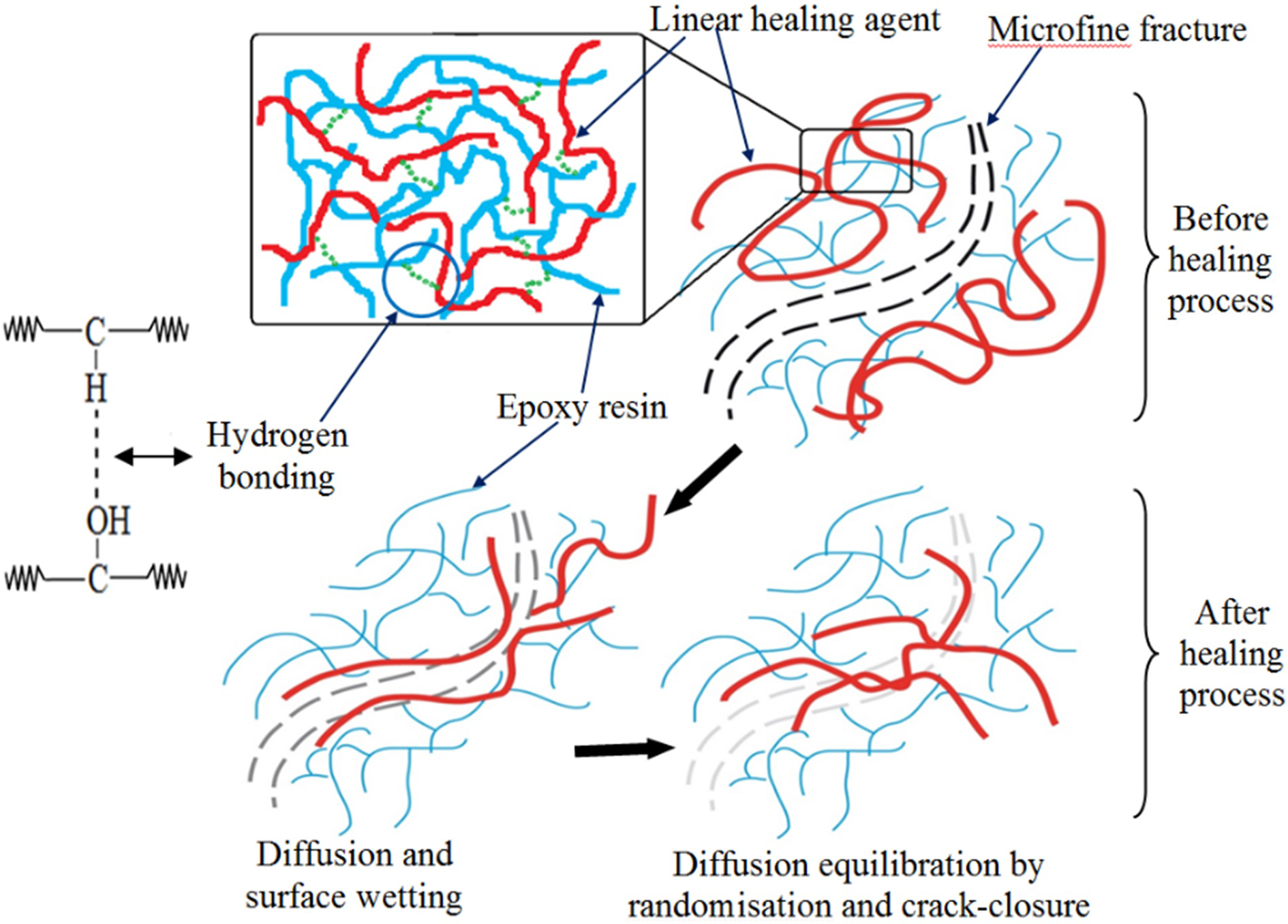
Schematic of self-healing mechanism of the solid state healing resin.
In addition, there is no significant change in the ATR spectrum for the molecular structure of the modified resin before (Figure 8c) and after (Figure 8b) the healing process. This result confirms that the concept of resin recovery is based on the random diffusion of healing agents rather than chemical reactions for crack closure. Important peaks such as ester functional groups (C=O); at a wavelength of 1730 cm−1, are based on the reaction between the functionalized carbonyl groups of the anhydride and the epoxy from DGEBA (Figure 8b). This peak is not evident in the spectrum of standard PDGEBA (Figure 8a). Moreover, the opening of the epoxy ring was expected to reduce the intensity of the asymmetric ring stretching band for the epoxy ring at 910 cm−1 (Figure 8b). Meanwhile, the peak at wavelengths of ∼915 cm−1 represents of asymmetric ring stretching band for the epoxy ring (C-O-C) in PDGEBA (healing agent) with glycidyl end-caps (Figure 8a).
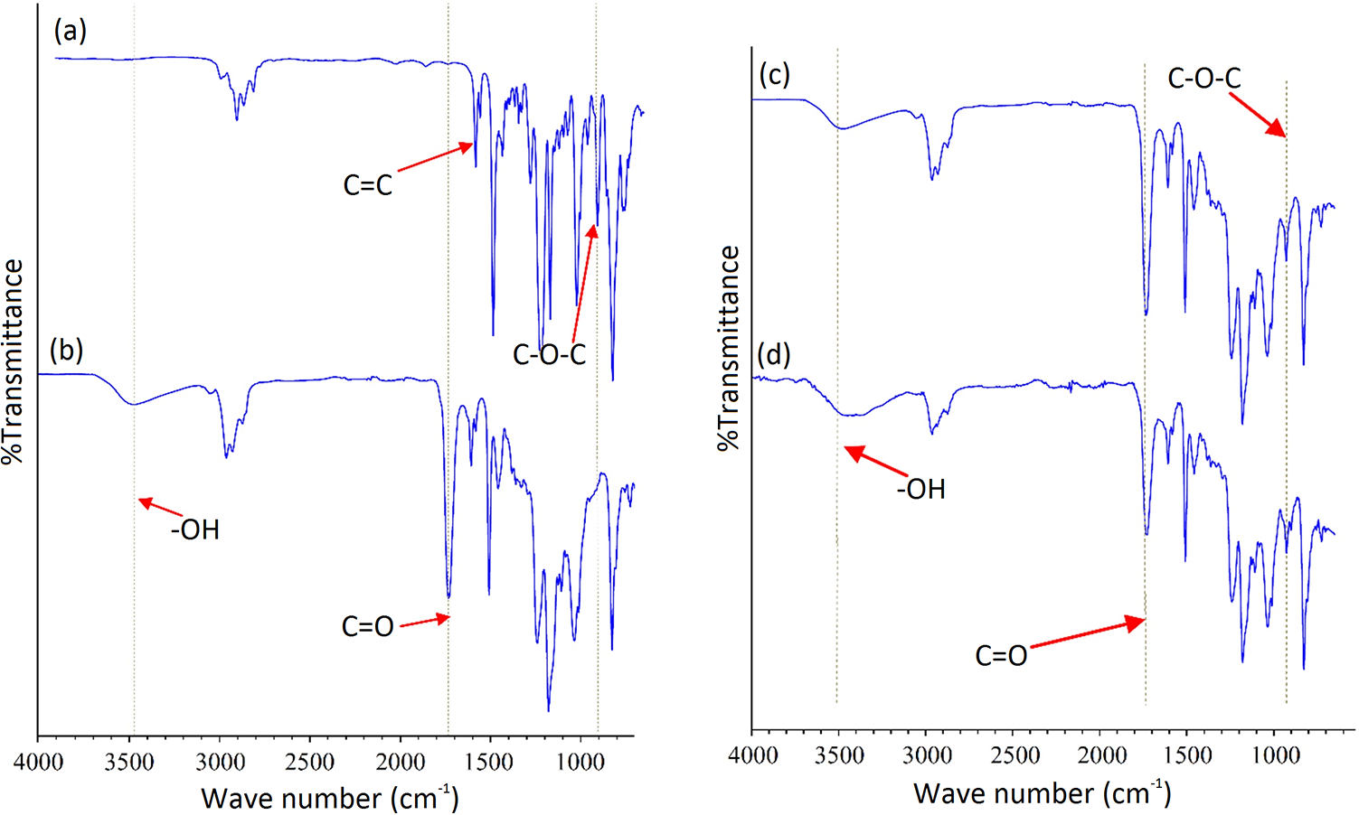
ATR spectrum of (a) PDGEBA (healing agent), (b) control/neat resin (without healing agent) and modified resin (c) before and (d) after healing cycle (at 160°C for 6h).
Residual strength assessment
Fatigue loading criteria can be classified into four major categories: macroscopic fatigue strength criterion, criterion based on residual strength, criteria based on the residual stiffness and finally criteria based on actual damage mechanisms.29,30 In this study, in addition to comparing with the number of cycles of fatigue life (Nf), the effect of solid state self-healing systems on fatigue was also identified by comparing the changes in the tensile strength residues for the neat and modified resin.
Degradation of residual tensile strength with the number of cycles, for the neat and modified resin after 600 fatigue cycles are plotted in Figure 9a. It shows that the relationship between the degradation of the tensile strength and the number of fatigue cycles. It can be observed when the matrix resin is charged with fatigue stress up to 600 cycles, the residual strength of the material has dropped. Residual strength and fatigue life of composites were seen descending very quickly when the load sequence changed repeatedly after only a few cycles of load. Given the residual tensile strength is almost similar for the neat and modified resin, it can be said that the addition of healing agents in an epoxy resin matrix does not affect the properties of fatigue. Overall, based on the graph of the degradation of this tensile strength, it is clear that the control and modified resin undergo approximately nearly half a strength degradation from the original strength of the material after exposure to 600 fatigue cycles.

Residue strength for the neat and modified resin after (a) 600 cycle of fatigue test or (b) with the healing process for each 600 cycle of fatigue test; with σa = 50 % σo.
To investigate the effect of solid state self-healing system on the fatigue loading, residual strength for control and modified resin were compared. Degradation of residual tensile strength with the number of cycles for the control and modified resin; with and without the recovery process, is plotted in Figure 9b. Residual strength of modified resin that undergoes recovery after 600 cycles is found to be higher than the control resin strength residues (without recovery agents). In addition, the modified resin strength residue charged with the healing process was also found to decrease at a slower rate throughout the load cycle up to 2400 fatigue cycles, compared to the control resin strength residue (without the recovery agent). The residual value of the control and modified resin, with and without the recovery cycle, are summarized in Table 2.
Residue strength of neat and modified resin after fatigue cycles or/and healing process.

The reduction of the residual strength even after multiple healing/thermal cycles can be explained by the effect of physical aging in the “free-volume theory of diffusion molecule.” Linear polymer diffusion is closely related to the ability of a molecular structure to move base on the free volume that exists in the matrix resin. The gradual rearrangement of molecular chains can occur during aging at/or above the glass transition temperature (Tg) which enables the packing of the molecules to be enhanced. This reduces the flexibility of the molecular structure of HA or polymer network which is related to the reduction in segmental mobility for the diffusion of HA for healing. The possibility of compaction of molecules and a reduction in free volume after multiple healing/thermal cycles was reported from the changes in volume and thermal expansivity of the healable resin which resulted from the relaxation of the network through the chain conformation.7,13
Morphology study
Self-healing ability of the resin matrix due to micro-cracking caused by fatigue test has been analyzed using optical microscopy and scanning electron microscope (SEM). Optical microscopy was used to study the self-healing ability on the surface of the resin matrix while scanning electron microscope (SEM) was used to study the cross surface of the resin matrix that was experiencing fatigue cracks.
Figure 10 shows a micrograph on the surface of a modified resin that has undergone a fatigue test. Fatigue cracks can be clearly seen on the sample surface (Figure 10a). The micrograph of modified resin specimens, before and after the recovery is shown in Figure 9b. Fatigue crack on the specimen surface was exposed to stress after 600 cycles of fatigue can be clearly seen in Figure 10a, b1 with 50x magnification. Figure 10b2 shows the fatigue crack that had been restored after the healing process at 160°C for 6 hours. Fatigue cracks would disappear on the surface of the matrix resin after being heated at 160°C on the first (Figure 10b2), the second and third healing cycles. 31 After the fourth (Figure 10b4) and fifth recovery cycle, fatigue cracks appeared to be not fully recovered/disappear. In agreement, Figure 6 shows that the modified resin was appeared to be broken after the fourth or fifth healing cycle during the fatigue load test. In general, fatigue is a type of dangerous and hidden failure that occurs without warning. Fatigue processes occur at the onset of cracking and are followed by crack propagation, and usually, the fractured surface is perpendicular to the direction of the applied stress.

(a) Micro-cracking micrograph on the surface of the modified resin matrix (a) during the fatigue strain test is carried out and (b) after subjected to the healing cycle; before (1, 3) and after (2, 4) the recovery process. Scale bars are 10 μm.
The investigation on the effect of fatigue on the surface of the matrix resin was observed. The micrograph of fully fracture fatigue crack surface specimen is studied and shown in Figure 11. Fatigue cracking surfaces of both matrix resins indicate outer nominal morphology. In agreement with the schematic concept of a typical fatigue-fracture matrix surface (Figure 11a), the matrix resin shows that fatigue cracked start from the surface of the matrix and slipped into specimens in a semi-elliptical form, i.e. thumbnail, shaped crack (Figure 11b). According to the general observation in polymers, 22 regions such as slender mirrors were characterized by early fatigue crack growth regions, which were followed by relatively rough radius, and fast-fracturing regions. The surface of the resin matrix that experienced fatigue cracks were also examined using a scanning electron microscope (SEM) as shown in Figure 11c. River markings sign has been observed on the surface of the resin matrix. They show the direction of the progression of a fatigue crack. River marks emerge most frequently in the relatively fast-growing sections of the fatigue zone, and, other than indicating the direction of crack growth, they supply little information that can be used to diagnose the cause of the failure. 3

The (a) schematic, (b) micrograph and (c) SEM image of the fatigue-fracture surface of modified resin specimen that is completely broken.
Conclusion
Under the fatigue test, the fatigue life of healable resin containing PDGEBA was shown to be increased by 50% compared to the control resin’s fatigue life (without a healing agent). Moreover, the healable resin also showed an improvement in residual strength than the control resin after exposure to fatigue cycles. The fatigue-healing process was proven through the surface and cross-section resin morphology analyses using microscopy optic and SEM. The results obtained from this study confirmed that the solid state self-healing system is very effective in obstructing fatigue crack propagation and monotonic fracture, thus effectively provides a self-healing polymer material with higher endurance limits or durability.
Footnotes
Acknowledgements
The authors acknowledge the financial support of this study by the Government of Malaysia through the grant number of GGP-2017-086. The authors also wish to thank the Centre for Advanced Materials and Renewable Resources, Faculty of Science and Technology and the Department of Mechanical and Engineering, Faculty of Engineering and Architecture, the National University of Malaysia for the facilities and support of this project.
Declaration of conflicting interests
The author(s) declared no potential conflicts of interest with respect to the research, authorship, and/or publication of this article.
Funding
The author(s) received no financial support for the research, authorship, and/or publication of this article.