
Abstract
Assembly of Most composite components requires secondary machining operations, such as drilling. Various methods such as drilling by means of twist drills bits, laser beam and abrasive jet machining are used to drill these materials, and twist drill bit is considered to be the most inexpensive and most commonly used method. The present paper is an attempt to investigate the effect of feed rate and rotational speed of drill bit on delamination rate during drilling of a 1.4 mm thick Kevlar-epoxy composite sheet as well as the hole diameter error in this sheet. Kevlar fibers are widely used in composites that are utilized in the aerospace industry. 4 feed rate levels and 4 spindle speed levels were selected to conduct a full-factorial experiment and each experiment was repeated three times. The effects of pre-drilling, compressed air, layer of leather on a Kevlar-epoxy sheet and the innovative strategy of simultaneous use of pre-drilling and a leather layer, on the delamination factor and hole diameter error was also investigated in the present study. The results indicate a significant reduction in delamination factor and hole diameter error in simultaneous use of pre-drilling and a leather layer on the composite sheet.
Introduction
The unique properties of composites has led to extensive application of these materials in aerospace, military, marine and automotive industries. The ratio of strength to weight, toughness, high thermal transfer coefficient as well as high corrosion, creep and abrasion resistance are the hallmarks of composites. These features, as well as the flexibility in fabrication of continuous fiber-reinforced composite materials, have made composites a good alternative to metal alloys. Composite parts often require secondary machining process before they can be assembled, and drilling is the most common machining operation applied on them. Drilling is a type of machining operation that uses a drill bit to make a hole with a circular cross section on the parts. The drill bit is forced against the piece and rotated at the set speed. This pushes the cutting edges against the part, cutting off chips from the hole as it is drilled. Bolts and rivets are usually used to connect composite parts. For example, there are more than 100,000 holes in a small airplane engine or millions of holes in a large aircraft. The holes created to assemble these parts must be highly precise and free of any defects so that the joints can be made properly and the required mechanical properties can be met.
Failure to notice the quality standards of the holes such as waviness and surface roughness, and deviation from roundness and straightness of hole, can increase the stress exerted on the joints and finally lead to their failure. The concentration of stress, delamination and microscopic cracks created during the drilling process can also reduce the efficiency of composite. 1 Today, in the aerospace industry, composite materials are increasingly replacing the material used in body and wings of aircrafts, for example, in the Airbus A350, these materials account for 65% of the empty airplane’s weight. 2
Delamination is one of the most important defects that may emerge during machining of fiber-reinforced composites. The separation of the composite reinforcing layers, which are attached to each other by the underlying phase, is called delamination. The upward peel up of the fiber-reinforced composite in the hole inlet and the downward push out of fiber-reinforced composite at the outlet of the hole are two main factors that can lead to delamination in the fiber reinforced polymer composites as shown in Figure 1. The axial force is the main cause of delamination in fiber-reinforced composites. The abrasion of tools in the drilling of fiber-reinforced composites increases the axial force which consequently leads to increased delamination.3,4 Proper selection of cutting parameters (spindle speed and feed rate), the tool geometry (chisel edge, point angle, relief angle), special tools (step drill bit, wood drill bit), drill material (high-speed steel, carbide) and machining strategy (pre-drilling,…) can help reduce the possible defects created in the hole. 5 Extensive studies have been carried out on conventional drilling of composites, some of which investigate the effect of input parameters such as spindle speed, feed rate, tool geometry and materials on output parameters such as delamination and axial force through some comprehensive experiments.2,6 The minimization of delamination, which is one of the most important factors affecting the quality of holes, has been the subject of some other studies.7,8 The proper selection of tools as well as the tool material and coating type helps to reduce possible defects in the drilling of composites. Therefore, another group of researchers has specifically studied the effect of different parameters of tool geometry and materials on the final quality of the holes.9,10 Lachaud et al. 11 studied composite drilling and categorized the composite defects in four groups: delamination at the inlet and outlet of holes, temperature-dependent defects and geometric defects. Temperature dependent defects are caused by the contact and friction between the drill and the hole wall.

Delamination mechanisms in fiber-reinforced composites. a) Delamination due to the upward peel up of the fibers at the inlet of the hole; b) Delamination due to the downward push out of the fibers at the outlet of the hole.
The strings of glass, Kevlar and carbon are most widely used in fiber-reinforced composites. The applications of Kevlar fiber reinforced composites include the leading edge of the wing and components of the cone-shaped body of plane. 12 Of all synthetic fiber reinforced composites, machining of Kevlar reinforced composites is associated with a lot of problems due to its special properties. Anisotropy, heterogeneity, the heat generated by friction during machining, and special properties of Kevlar fibers are the reasons that make machining of Kevlar reinforced composites more difficult. 13 Unlike Kevlar reinforced composite drilling, drilling of glass and carbon fiber reinforced composites has been subjected to extensive studies.
In 2015 a review article on the mechanical and thermal properties of Kevlar fibers and Kevlar reinforced composites was published by Singh and Samanta. 14 In the suggestion for further studies section, they pointed to the need to investigate the optimization of cutting parameters and tool geometry in the Kevlar composite machining processes, including drilling to improve the quality of holes and the delamination control. In general, little research has been done on the machining processes and the drilling of Kevlar composite in particular. One of the few articles on Kevlar composite drilling with twist drill bit include Bhattacharyya and Horrigan 15 who regard the machining of Kevlar reinforced composites as the hardest composite machining due to flexibility and toughness of these fibers. They performed a process of drilling on a 6 mm thick Kevlar-epoxy composite sheet using conventional drill bits and drill bits with special geometry, through conventional machining and cryogenic machining (by direct spray of liquid nitrogen into the hole). The peel up and push out of the fibers in the inlet and outlet of holes respectively and formation of fuzz around the hole were the most important defects in the drilling of this composite. The lowest level of tool wear and the best surface finish has been reported for drill bit with special geometry and large helix angle in cryogenic condition. Bhattacharyya and Horrigan concluded that any increase in force would increase delamination, but the use of a sheet as a backup would reduce delamination.
Insufficient information on the selection of cutting parameters, geometry and material of tools, and appropriate strategy for drilling of Kevlar-reinforced composites, increase the need to optimize cutting parameters and investigate the effect of drilling techniques on the quality of the holes. Defects created during drilling can cause a composite piece to be returned. Due to the high price of Kevlar fibers, minimization of such defects is of particular importance. The present study is an attempt to investigate delamination and hole diameter error that may appear during drilling of Kevlar-epoxy composite thin sheets and to evaluate the effect of cutting parameters and different machining strategies on these defects. The results indicate a significantly positive effect of simultaneous use of pre-drilling and leather cloth, on reduction the holes’ defects.
Experimental tests
In the composite sample examined in this paper, epoxy is the matrix phase that is reinforced by eight layers of Kevlar 49 cloths. This 1.4 mm thick composite sheet is made through hand lay-up of Kevlar layers and is cut in size of 21 × 29 cm. The characteristics of the fiber and the matrix phase of this composite are listed in Table 1.
Properties of Du Pont Kevlar 49 yarns and epoxy resin.

* Epoxy impregnated strands ASTM D2343
Kevlar-epoxy composite sheet drilling tests were performed using a VMC 1000 three-axis CNC milling machine. In order to find the appropriate range of machining parameters for testing, the process of drilling was carried out in a wide range of spindle speeds and feed rates, and finally, four spindle speeds of 300, 1200, 2100 and 3000 rpm, and four feed rates of 50, 134, 218 and 300 mm/min were selected for final tests, according to the apparent quality of the holes. The Kevlar-epoxy thin-sheet drilling is not possible without backup sheets, due to defects that may arise by bending of the sheet. Therefore, a 20 mm thick Teflon plate was used as a composite sheet backup. The composite sheet was completely restrained by clamps from three directions. Drilling was performed using a HSS twist drill type DIN 338 TYPE N with 118-degree point angle and diameter of 10 mm. The experimental setup and the used twist drill bit are shown in Figure 2.
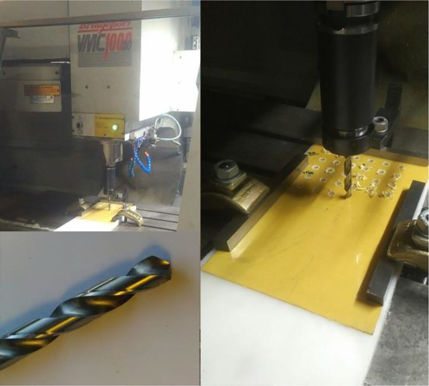
Experimental setup and the drill bit.
In addition to drilling by means of a typical twist drill bit, the effect of four different strategies on delamination and hole diameter error was also investigated. These strategies include the use of pre-drilling, compressed air cooling, using leather layer on the composite surface, and simultaneous use of pre-drilling and leather layer. The optimum cutting parameters obtained in the conventional drilling process for having the minimum hole diameter errors and delamination, are used as input cutting parameters in each of these four machining strategies. A new tool was used to test each strategy. In order to investigate the effect of pre-drilling, first a HSS drill of DIN 338 TYPE N with 118-degree point angle and diameter of 6 mm, and then a main drill with a diameter of 10 mm were used. In order to carry out drilling with compressed air cooling, an air outlet nozzle with 6-bar air pressure was fixed at a distance of 10 mm away from the drill bit at an angle of 45 degrees.
In the innovative method of drilling, a 20 × 20 cm artificial leather layer with thickness of 1 mm is used as the coating on the composite sheet. When the drill bit penetrates into the composite sheet, this layer of leather stands between the relief angle of drill bit and the hole, and begins to rotate as the drill bit moves. Finally, in the strategy of simultaneous use of pre-drilling and the leather layer, first the sheet was pre-drilled without using the leather layer, and then, the final drilling was done with the leather cloth on the sheet.
The full factorial design was used and a total of 16 experiments were conducted. To reduce the effects of heterogeneity of the workpiece material and minimize random errors, each experiment was repeated three times, and the mean values of delamination and hole diameter error were used for analysis purposes.
In order to measure the delamination, the lower surface of the composite sheet was exposed to light and the high-quality photographs were taken from the upper surface at the same time. The low thickness of the sheet causes light to pass through the composite and make the delaminated parts easily visible. Figure 3 presents delamination in the sample sheet in one of the experimental tests as well as the necessary parameters for measuring delamination. To determine the extent of damage to the area around holes and measure the delamination level, the delamination factor Fd was used where Dmax is the largest damaged diameter and D denotes the nominal diameter of the hole 16 :


Delamination and the parameters for calculating delamination factor.
The uncut fibers and fuzzes are among other defects that may appear during the Kevlar-epoxy composite drilling, which reduce the diameter of holes and increase the stress on the joints at the time of use. The hole diameter error that expresses the difference between the nominal hole diameter (D) and the actual hole diameter (Dmin) and is represented by Eh is used to evaluate this defect:

Results and discussion
Drilling with a typical twist drill bit
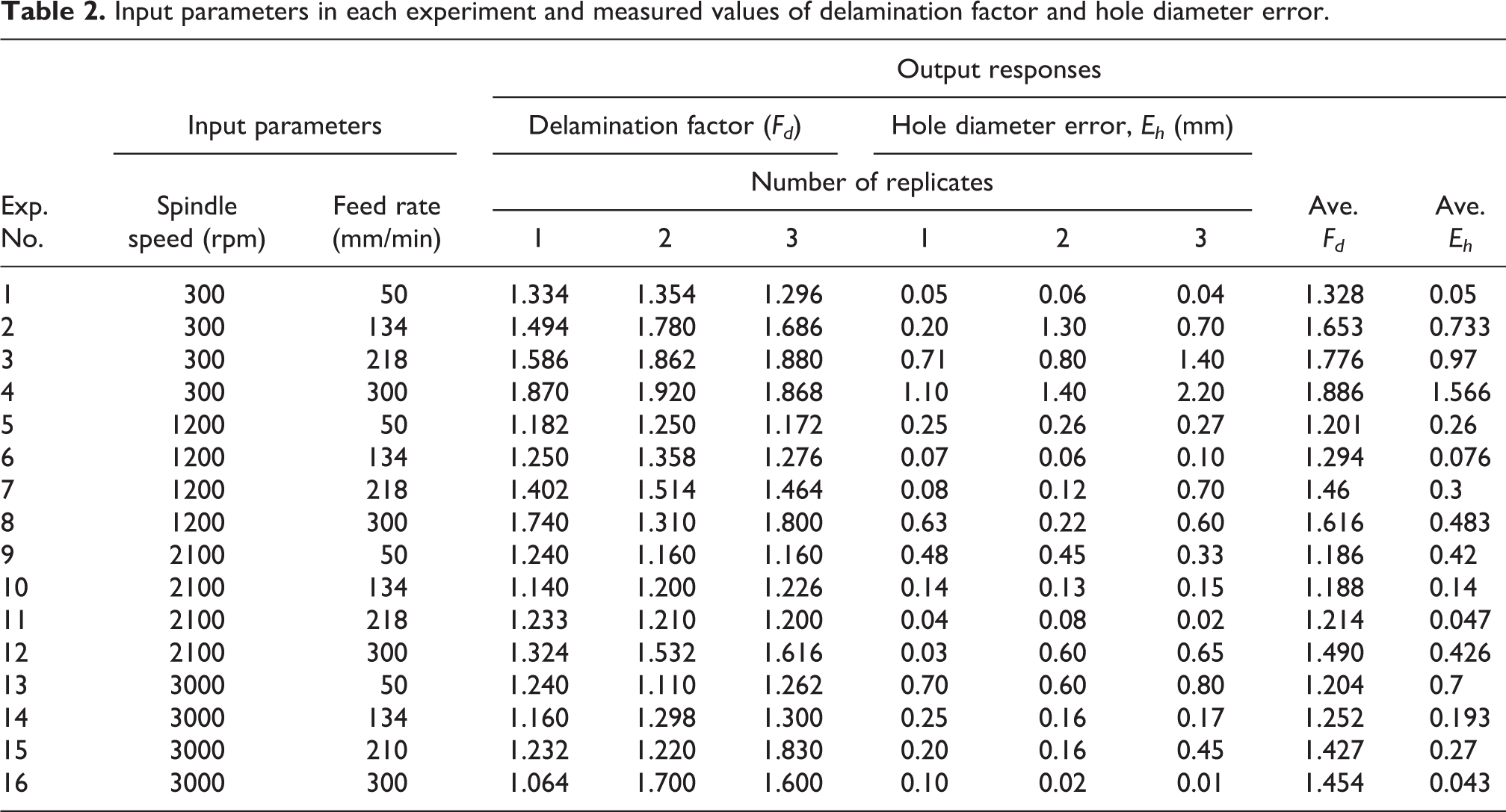
Figure 4 shows the sheet subjected to experimental tests with a typical twist drill bit. The fuzzes that are created due to inappropriate selection of machining parameters can be seen in Figure 4. The delamination rate and hole diameter error values for the holes on this sheet are calculated. Table 2 shows the used parameters as well as the delamination and hole diameter error values in each experiment.

A sample of Composite sheet after the drilling experiments.
Input parameters in each experiment and measured values of delamination factor and hole diameter error.
The normal probability plot of the residuals for the delamination factor and the hole diameter error represents the proximity of the residual values to the straight line, and thus the normal distribution of the values. This generally indicates that the model is accurate enough for conclusion.
Figure 5, shows the interaction effects of the spindle speed and the feed rate on delamination. As the figure shows, at the feed rates of 50, 134, and 218 mm/min, any increase in spindle speed from 300 to 2100 rpm will lead to reduction of delamination but the increase in the spindle speed from 2100 to 3000 rpm, will increase delamination. Generally, as the spindle speed increases, the heat generated by the friction between the drill and the composite makes the composite softer and this consequently makes the composite easier to cut, but with an increase in speed spindle from 2100 to 3000 rpm, the excessive rise of temperature (reaching the critical temperature) and reduced adhesion between the composite layers will lead to an increase in delamination. In the machining of glass fiber reinforced plastics Campos Rubio et al. 17 concluded that any increase in spindle speed leads to a decline in delamination factor. According to them, the decline in delamination can be attributed to the generated heat, and ultimately to the softening of the composite matrix. At feed rate of 300 mm/min, the increase in spindle speed leads to a decline in delamination factor. The difference between this feed rate and the other three rates is that with increase of spindle speed from 2100 to 3000 rpm, the trend of decline in delamination would persist. The reason for this behavior is that the high feed rate of the drill bit has caused the drill to penetrate into the workpiece in a short period of time, therefore the drilling operation has finished before enough frictional heat is generated. It should be noted, however, that the slope of delamination changes at the feed rate of 300 mm/min has decreased as the spindle speed increases and the critical temperature is approached. In other words, in the spindle speed range of 2100 to 3000 rpm, the delamination factor follows a rising trend at feed rates of 50, 134, and 218 mm/min due to transcending the critical temperature; but would follow a falling trend at feed rate of 300 mm/min due to the failure to reach the critical temperature.

Interaction plot for delamination vs spindle speed and feed rate.
Figure 6 shows the interaction effects of spindle speed and feed rate on the hole diameter error. At spindle speed of 300 rpm, any rise in the feed rate would lead to an increase in hole diameter error. This behavior could be attributed to increased axial force that produces long uncut fibers and in some cases, rupture of the composite instead of cutting it. In the feed rate of 50 mm/min, the increase in spindle speed leads to increased friction between the tool and the composite, resulting in generation of higher temperatures. The excessive heat causes excessive softening of composite, and the higher spindle speed leads to formation of short uncut fibers known as fuzzy surfaces. At the feed rate of 134 mm/min, the increase in spindle speed up to 1200 rpm and generation of desirable heat, leads to decrease in hole diameter error and in case the spindle speed exceeds 1200 rpm, the hole diameter error would increase because the critical temperature is exceeded. The same behavior is observed at the feed rate of 218 mm/min, except that in this case, due to the higher feed rate and the reduction of time required for transfer of heat to the adjacent layers of the hole, the critical temperature is reached at speeds of spindle above 2100 rpm. According to Figure 6, the increase in spindle speed at the feed rate of 300 mm/min leads to a generation of desirable heat, and easier cutting of the fiber and decline of the hole diameter error accordingly. The high hole diameter error at feed rate of 300 mm/min can be attributed to high axial force that leads to formation of long uncut fibers. At spindle speed of 3000 rpm, increased hole diameter error occurs at low feed rates. The high spindle speed and low feed rate leads to an increase in duration of drill contact with the composite and generation of more heat and consequently to development of fuzzy surface inside the hole. The noteworthy point for controlling uncut fibers and the developed fuzzes is to observe the proper ratio between spindle speed and feed rate. According to Figure 6, low spindle speed and high fed rate also increase the hole diameter error.

Interaction plot for hole diameter error vs spindle speed and feed rate.
Wang et al. 12 introduced the excessive heat generated in milling of Kevlar-reinforced composites as one of the major problems in the machining of these composites and used cryogenic machining to reduce this heat. According to the results of their study, temperature reduction has little effect on the fibers and more significant effect on the toughness and strength of the composite matrix. They realized that reduction of temperature increases the modulus and tensile strength of the composite.
Khashaba et al. 4 also investigated the machinability of glass fiber-reinforced composite, and concluded that high-speed drilling would generate more heat and ultimately lead to increased surface roughness. In a review article on drilling of composites with polymer matrix, Khashaba 18 argued that the high temperature and the low thermal transfer coefficient of the composite matrix during high-speed drilling are the major causes of composite matrix decomposition and damage. Rise of temperature around the cutting edges of the tool leads to deterioration of the composite matrix and thermal damages and consequently creates rough and fuzzy hole edges. According to Khashaba, the relationship between heat generated and thermal and mechanical defects in the drilling of polymer composites is an unresolved problem that still needs further studies.
It should be noted that although each test was repeated for 3 times and the delamination factor and hole diameter error were averaged, according to the laboratory observations, the non-homogeneous and anisotropy properties of the Kevlar-epoxy composite sheet cause sometimes the three holes with the same cutting parameters to show different outward conditions. This can be seen in Table 2. For a better analysis of the empirical observations, the main effects plot of the spindle speed and feed rate on the delamination factor and hole diameter error are presented below.
Figure 7 shows the diagram of the spindle speed and feed rate main effects on the delamination factor. With rise of spindle speed to 2100 rpm, the delamination factor decreases due to reduction of the axial force, rise in temperature and the softening of the composite. As the spindle speed increases from 2100 to 3000 rpm, further rise in temperature and excessive softening of the composite lead to increased delamination of the composite. The increase in feed rate leads to an increase in delamination with a roughly uniform slope. Increased feed rate directly affects the amount of axial force and leads to the separation of the composite layers. The study of Gaitonde et al. 19 on the high-speed drilling of carbon fiber reinforced plastics showed that reduction of feed rate and increase in spindle speed play an important role in reduction of delamination. Findings of References 18 and 19 are generally consistent with the findings of this paper presented in Figure 7.

Main effects plot for delamination.
The diagram of the main effects of spindle speed and feed rate on the hole diameter error is presented in Figure 8. The uncut fibers and fuzzy surfaces are the main factors that contribute to hole diameter error. The increased hole diameter error at the spindle speed of 300 rpm can be attributed to long uncut fibers that are produced as a result of high axial force. This high force can lead to rupture of the composites instead of cutting it. In the spindle speed range of 1200 to 3000 rpm, the hole diameter error has changed with a slight slope and has remained almost constant. Increasing feed rate from 50 to 134 mm/min leads to reduction of short uncut fibers (fuzzy surface) and minimization of hole diameter error. Increasing the feed rate from 134 to 300 mm/min, increases the hole diameter error which can be attributed to the formation of long and thicker uncut fibers. According to Figures 7 and 8, it can be argued that any increase in the cutting speed leads to reduction of delamination and hole diameter error, and any increase in the feed rate would increases both the delamination and the hole diameter error. In other words, the delamination and hole diameter error behavior is almost the same in the face of changes in spindle speed and feed rate parameters.

Main effects plot for hole diameter error.
Evaluation of Figures 5 to 8 and laboratory observations shows that observing the proper proportion between the spindle speed and the feed rate has a significant effect on the delamination factor and the hole diameter error. The contour plot is used to test this hypothesis. The contour plots of delamination and hole diameter error for different spindle speed and feed rate values are presented in Figures 9 and 10, respectively. The impact of increased feed rate on delamination as well as its relationship with spindle speed has been presented in Figure 9. Minimum delamination value is observed in the spindle speed range of 1800 to 2500 rpm and the feed rate of less than 150 mm/min. To increase the drilling speed and relatively control the delamination at the same time, one can apply the maximum possible feed rate at the spindle speed of 2100 rpm. Durão et al.10 investigated the effect of tool geometry on the delamination during carbon fiber reinforced sheet drilling, and concluded that low feed rates and consequently, low axial force reduce the risk of delamination. It should be noted that low feed rate can lead to thermal degradation and also reduce the speed of production.

Contour plot of delamination factor vs. spindle speed and feed rate.

Contour plot of hole diameter error vs. spindle speed and feed rate.
Observance of the proper proportion between spindle speed and feed rate in order to reduce the hole diameter error is presented clearly in Figure 10. High spindle speed and low feed rate will lead to generation of excessive heat and excessive softening of the composite which will in turn lead to formation of high-density short fuzzes. At low spindle speeds and high feed rate, high axial forces produce long uncut fibers and, in some cases, rupture of composite fibers instead of cutting it. The dotted drawn in Figure 10 shows a safe range for proper selection of spindle speed and feed rate to achieve the minimum hole diameter error.
In the optimization performed in the Minitab software, delamination and hole diameter error outputs were taken into account at the same time and the spindle speed of 2100 rpm and feed rate of 218 mm/min were introduced as optimal parameters. In this optimization, the weight and significance of the delamination and hole diameter error outputs were considered to be the same. In these optimal parameters, the mean delamination factor was 1.214 and the mean hole diameter error was 0.047.
Evaluation of different drilling strategies
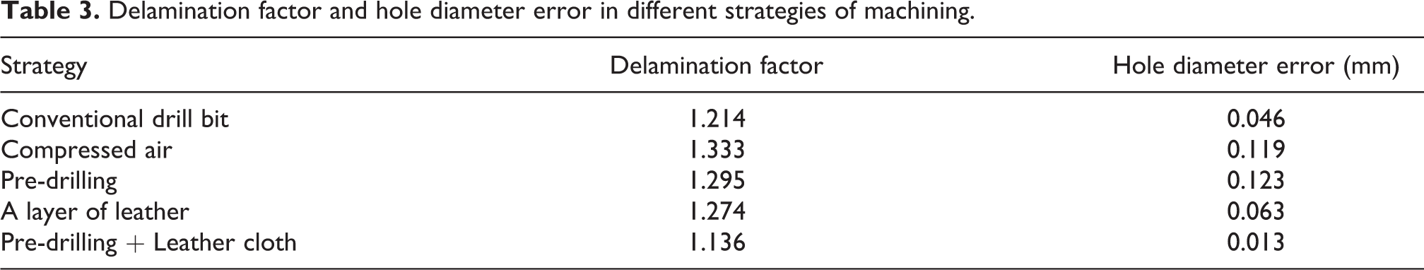
The next goal in this research is to investigate the effects of different machining strategies, such as using compressed air as a coolant, pre-drilling, an innovative method of using a layer of leather on the composite surface, and finally, the simultaneous use of the pre-drilling and leather cloth on the delamination rate and the hole diameter error. To this end, the process of drilling was performed based on the optimal parameters obtained in the previous section, i.e. the spindle speed of 2100 rpm and the feed rate of 218 mm/min, through different strategies. Experiments were carried out randomly in different locations of composite sheet with 3 repetitions and the results were compared to the optimal results obtained from drilling with a conventional drill bit. The results obtained for delamination factor and hole diameter error are presented in Table 3.
Delamination factor and hole diameter error in different strategies of machining.
Considering that the temperature rise during drilling up to the point of critical temperature improves the fibers cutting mechanism and reduces defects, compressed air cooling reduces the temperature and consequently leads to increased difficulty of fiber cutting which will in turn increase delamination rate and hole diameter error by 9.8% and 159%, respectively. It should be noted that this comparison is made with the optimal drilling process by means of a convectional drill bit and in some spindle speeds and feed rates where critical temperatures is reached during drilling with a conventional drill bit, the use of compressed air can reduce the hole diameter error and delamination factor.
The use of pre-drilling increased delamination factor by 6.7% and the hole diameter error by 167% which can be attributed to lower engagement of drill bit with the composite surface that leads to generation of less heat compared to the optimized mode.
The use of a leather layer on the composite sheet, however, reduces the delamination rate and hole diameter error compared to the cases where compressed air is used as a coolant and where pre-drilling is applied on the composite, but delamination factor and hole diameter error in this mode are higher than the optimized drilling mode using conventional drill bits. The occurrence of defects during the drilling of thin sheets of composites can also be attributed to the sheet peel up by the drill. The innovative and new method of using a leather layer and pre-drilling prevents sheet peel up to a large extent, reducing the delamination and hole diameter error factor by 6.6% and 71%, respectively compared to the optimal drilling mode by a conventional drill bit. Reduction of defects in the simultaneous use of the leather layer and pre-drilling can also be attributed to reduced vibrations and higher stability of the drill during the drilling operation. After being pierced by the drill bit and being placed around it, the leather cloth would act as a support for the drill by filling its relief angle, and will consequently prevent drill vibrations and occurrence of defects in the composite.
Conclusion
The present study is an attempt to investigate the most important defects in the thin Kevlar-epoxy sheets with conventional twist drill bits, and experimentally study the effect of spindle speed, feed rate, and machining conditions on the delamination factor and hole diameter error. The most important findings of this research are as follows: Taking into account the delamination factor and the hole diameter error outputs, the best result was obtained for the conventional twist drill bit at spindle speed of 2100 rpm and feed rate of 218 mm/min. The most important factor in controlling delamination rate and hole diameter error during drilling of Kevlar-epoxy composite sheets is observance of the proper proportion between spindle speed and feed rate. High spindle speed and low feed rate leads to development of a fuzzy surface while low spindle speed and high feed rate results in creation of long uncut fibers and, in some cases, rupture of composite fibers. Any rise in feed rate leads to increased delamination and hole diameter error, and increased spindle speed up to 2100 rpm, will reduce the delamination factor and the hole diameter error. Further rise of the spindle speed up to 3000 rpm will lead to a slight increase in the delamination factor and hole diameter error. The general behavior of delamination and hole diameter error defects is almost the same for different changes in the spindle speed and the feed rate parameters. The use of compressed air as a coolant, the use of pre-drilling and the technique of placing a leather layer on the composite sheet has not helped to improve delamination rate and the hole diameter error, but simultaneous use of the pre-drilling and leather cloth has had a significant effect on the reduction of delamination rate and the hole diameter error. In this new and innovative strategy, the delamination factor and hole diameter error have declined by 6.4% and 71% respectively compared to optimized drilling case by means of conventional twist drill bits.
Footnotes
Declaration of conflicting interests
The author(s) declared no potential conflicts of interest with respect to the research, authorship, and/or publication of this article.
Funding
The author(s) received no financial support for the research, authorship, and/or publication of this article.