
Abstract
In this experimental and statistical study, free vibration behavior of laminated composite beams with functionally graded fiber orientation angles was investigated under clamped-free boundary conditions. The beams were manufactured using E-glass/epoxy. Fiber orientation angles of the beams were analyzed based on Taguchi’s L9 (33) orthogonal array. The effect of fiber orientation angles and beams with optimum levels were assessed using analysis of signal-to-noise ratio. Significant laminates of the beams and their percent contributions on the free vibration responses were obtained using analysis of variance. According to this study, the increase of fiber orientation angle from 0° to 80° causes a decrease in the fundamental frequency behavior of laminated composite beams. The most effective control factors were found to be the first and the second laminates symbolized as L1 with 85.86% contribution, the third and the fourth laminates symbolized as L2 with 12.29% contribution, the fifth and the sixth laminates symbolized as L3 with 1.84% contribution, respectively. This study can be used as a reference for free vibration analysis of cantilever laminated composite beams made of functionally graded fiber orientation angles as experimentally and statistically.
Introduction
Composite materials are generally used in different areas such as automotive and aircraft industry, space vehicles, and machine elements. Some of the composite structures are made of laminated composites. Laminated composite structures such as beam and plate are generally manufactured using fiber and resin. Many studies in the literature have been carried out on free vibration analysis of the laminated composite beams and plates because of the widespread use of these materials. Boay 1 evaluated the free vibration behavior of laminated composite plates having central holes under different boundary conditions, and various modes of plates were evaluated. In analyses, the stacking sequence and lamination materials were constant. Kabir 2 evaluated the natural vibration characteristic of arbitrarily rectangular laminated plates made of composite materials and investigated the mode shapes of plates. Motaghian et al. 3 presented an analytical approach for free vibration behavior of rectangular plates on partial elastic foundation based on various mode sequences and they used different boundary conditions. Ghashochi-Bargh and Razavi 4 reported an analytical solution for prediction of the free vibration analysis of rectangular plates made of orthotropic and functionally graded materials, and they used different boundary conditions such as clamped and simply supported. Huang et al. 5 studied the natural vibration behavior of rectangular plates with orthotropic structures with different thicknesses, and they used various boundary conditions. Kameswara Rao et al. 6 presented an analytical approach for investigation of the free vibration behavior of laminated composite and sandwich beams, and they used higher order mixed theory. Chen et al. 7 evaluated the natural vibration behavior of generally laminated beams based on the state-space-based differential quadrature under different boundary conditions, and they determined various mode numbers. Topcu et al. 8 investigated the effect of stacking sequence influences on free vibration behavior of laminated composite beams, and they used finite element software ANSYS for numerical analysis. Atlihan et al. 9 evaluated the influences of stacking sequences of laminated beams made of composite materials on free vibration behavior using the differential quadrature method. They also investigated the first mode frequency of beams based on the experimental result. Luo and Hanagud 10 presented a new approach for composite beams which have through-width delamination, and they used this new method for free vibration analysis. Hu et al. 11 analyzed the vibration behavior of the delaminated beams and plates made of composite materials, and they used a higher order finite element approach. Ju et al. 12 investigated the modal analysis of delaminated composite plates using finite element approach. They also investigated various mode shapes of plates and used different boundary conditions. Lee 13 carried out the natural vibration behavior of a laminated beam containing delamination and used the layerwise theory. Żak et al. 14 studied the natural analysis of the multilayered delaminated beams and plates made of composite materials using numerical and experimental methods. Gadelrab 15 presented a study containing the free vibration of a laminated composite beam with delamination for different mode number. Chen et al. 16 studied the free vibration characteristics of thick rectangular plates designed using symmetrically laminates and they also utilized the p-Ritz method and higher order theory. Krishnaswamy et al. 17 presented a study containing analytical solutions on free vibration behavior of generally layered beams made of composite materials under different boundary conditions. Aydogdu and Timarci 18 investigated the vibration characteristics of square plates made of cross-ply laminates and they also employed various boundary conditions to their study. Matsunaga 19 studied the free vibration behavior and buckling stress of beams made of laminated composite and used higher order deformation theories. Qatu 20 determined the natural frequency characteristics of rectangular plates made of laminated composite and various boundary conditions were employed in the study. Aydogdu 21 determined the natural frequency behavior of angle-ply laminated beams under various boundary conditions. Chandrashekhara et al. 22 evaluated the free vibration characteristics of beams made of symmetrically laminated composite and used arbitrary boundary conditions in the analyses. Chandrashekhara and Bangera 23 determined the free vibration behavior of beams containing laminated composite and utilized beam element consisting of a refined shear flexible. Vo and Thai 24 evaluated the free vibration behavior of rectangular composite beams subjected to a load in the axial direction and also used refined shear deformation theory. It is clear from the abovementioned review that there are a lot of studies investigating the free vibration behavior of laminated composite beams and plates using numerical, experimental, and theoretical methods. In this study, experimental and statistical free vibration analysis of laminated composite beams made of E-glass/epoxy under free-clamped boundary conditions. Orientation angles of the layers were conducted using Taguchi’s L9 orthogonal array which has three control factors and three levels of each factor. Thus, nine different laminated composite beams were manufactured. Each beam has different fiber orientation angles. Experimental fundamental frequency analyses were carried out using DEWESoft vibration measurement device as know DEWE43A, and the results were analyzed using Minitab 15 software statistically.
Production of laminated composite
Laminated composite beams manufactured from E-glass/epoxy resin were used in the free vibration analysis. Firstly, the laminated composite plates with dimensions of 320 × 320 mm2 were manufactured to obtain the laminated composite beams. Hand lay-up was used as the production method. Each plate has different functionally graded fiber orientation angles from 0° to 80°, thus nine different plates were fabricated based on Taguchi’s L9 orthogonal array. The matrix was manufactured using Huntsman Araldite MY-740 epoxy and Aradur HY 918 -1 CH hardener. Nine laminated composite plates with 320 × 320 mm2 surface area were cured using the heater plate under 0.5 MPa constant pressure and 100°C temperature for 4 h. The laminated composite plates were allowed to cool at room temperature. After the production process, the beams with 35 × 220 mm2 dimensions were cut from plates. The laminated composite plates and the cutting operation are shown in Figure 1.

(a) Plates preparation and (b) cutting operation.
Statistical method
Nine experiments were performed using Taguchi experimental design methodology. The optimum results were obtained by reducing the number of experiments according to this method. The laminated composite beams were considered to be six plies. The stacking sequences of the beams were conducted using L9 (33) orthogonal array. This array has nine runs and three control levels. Each control level has three levels. The laminates were renamed as control factors. In the beams, the first and the second laminates were considered as the first control parameter, and these laminates were symbolized as L1. The third and the fourth laminates were determined to be the second control factor and symbolized as L2. Finally, the fifth and the sixth laminates were chosen to be the third control factor and symbolized as L3. Each level of each control factor was designed to be fiber orientation angle, thus the composite beams were produced using laminates with different fiber orientation angles from 0° to 80°. The control factors are presented in Table 1.
Laminates and their levels.
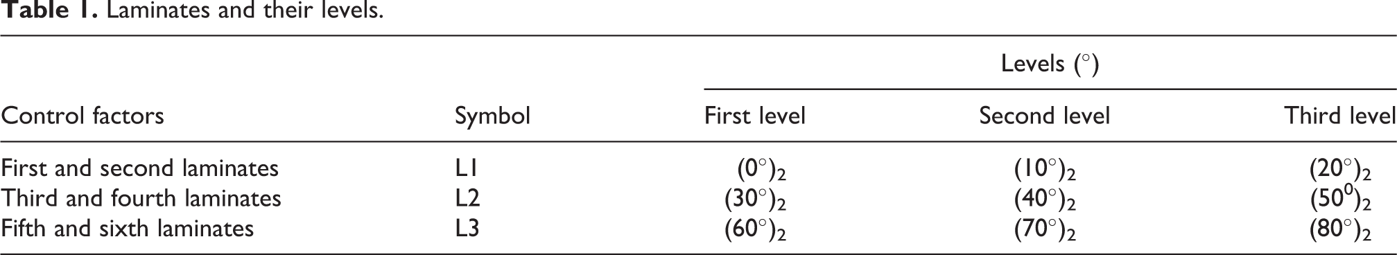
Taguchi method has different quality characteristics such as “Lower is Better,” “Nominal is Better,” and “Higher is Better”. In this study, the quality characteristic called as “Higher is Better” is selected as given in equation (1). 25

where n is the number of experiments in a trial and yi expresses ith data observed. Experimental results were converted to signal-to-noise (S/N) ratio data based on equation (1) to obtain the optimum levels of fiber orientation angles for the maximum free vibration data of the laminated composite beams. Each experiment was repeated three times to calculate S/N values. In all the designs, the plots and the analysis were performed using Minitab 15 software.
Experimental method
The experimental free vibration analysis of the laminated composite beams with functionally graded fiber orientation angles was carried out under clamped and free boundary conditions. Effective width and length of the beams were 35 mm and 185 mm, respectively. Thickness of the beams were measured to be 1.35 mm. Clamped length of the composite beams was also determined to be 35 mm. The free vibration analyses were carried out according to the impact hammer testing technique. Experimental fundamental frequency analysis was performed using DEWESoft DEWE43A vibration measurement device. The vibration measurement device has eight analog inputs including 200 kS/s/ch maximum sampling rate and 24-bit analog-to-digital converter. 26 An accelerometer called as the Dytran model 3224A1 in experimental procedure was positioned from a distance of 35 mm from the clamped end of beams in the experimental procedure. 26 The accelerometer has an average weight of 0.2 g, and it has also the sensitivity of 10 mV/g. 26 The setup for experimental free vibration behavior based on the first mode, and the laminated composite beams with functionally graded fiber orientation angles are shown in Figure 2.
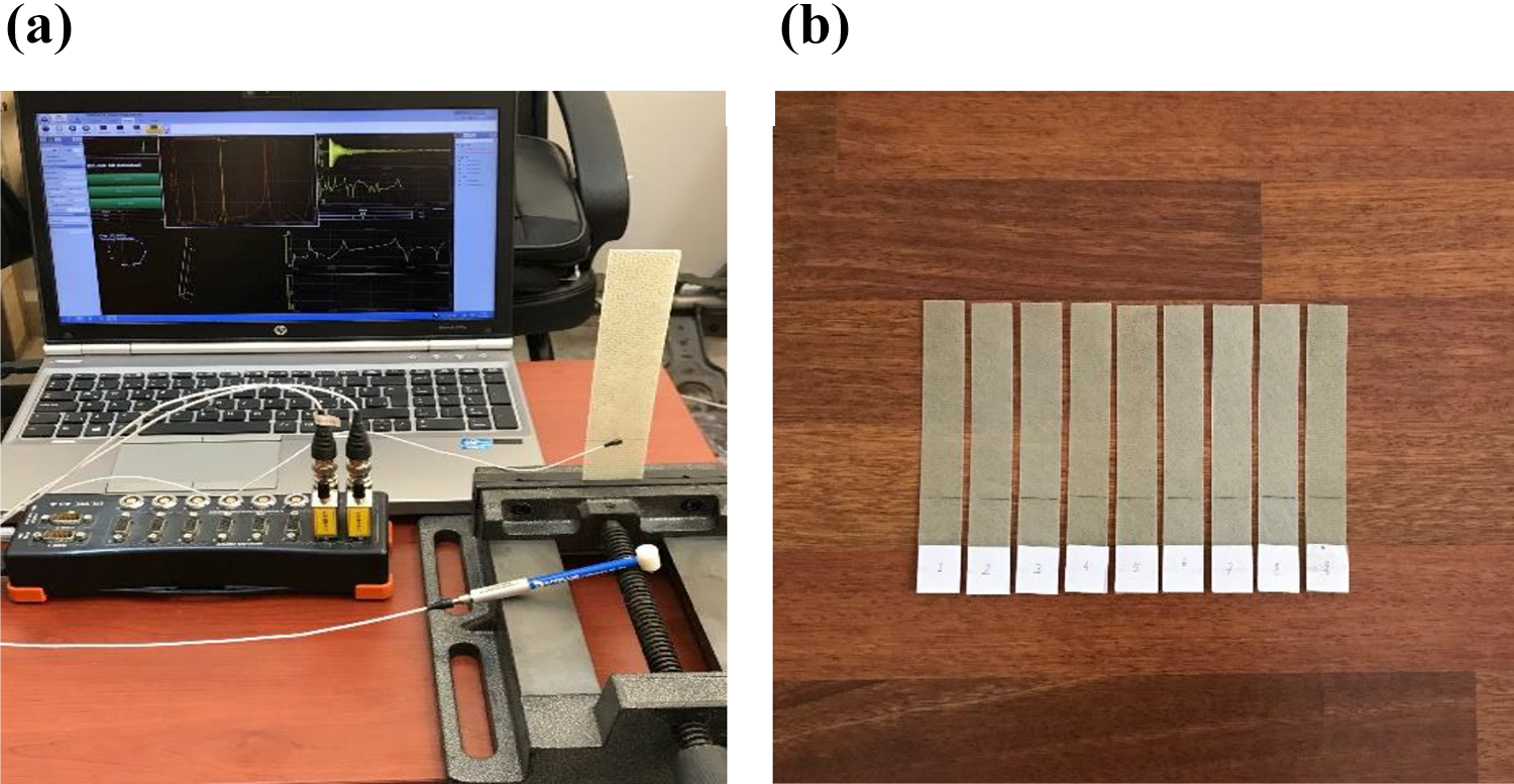
(a) Setup for fundamental frequency and (b) laminated composite beams.
Acceleration response and its frequency spectrum for the experimental result of the laminated composite beam with [0/0/30/30/60/60] stacking sequence are shown in Figure 3.

Acceleration response and its frequency spectrum of the optimum laminated composite beam.
Results and discussion
In this experimental and statistical study, free vibration analysis of laminated composite beams with functionally graded fiber orientation angles was investigated under clamped-free boundary conditions. Experimental vibration results were converted to S/N ratio data using Minitab 15 software according to the quality characteristic called as “Higher is Better,” thus the optimum result for the maximum data were determined. The experimental results and their S/N ratio data are listed in Table 2.
As seen from Table 2, the stacking sequences of laminated composite beams were conducted according to Taguchi’s L9 orthogonal array. Levels of the laminates were designed to be degree; thus, nine different laminated composite beams were analyzed. As understood from the analysis, the maximum fundamental frequency was obtained for the first test containing L1 with 0°, L2 with 30°, and L3 with 60°, whereas the minimum frequency for the first mode was found for last test containing L1 with 20°, L2 with 50°, and L3 with 70°. According to Taguchi’s L9 orthogonal array, overall mean
Results for quality characteristic and signal-to-noise ratio.

S/N: signal-to-noise.
Selection of optimum fiber angles
One of the main aims of the present study is to design the laminated composite beam with the optimum functionally graded fiber orientations and to analyze the optimum conditions, which will give the maximum fundamental frequency. To select the optimum fiber orientation angles for each laminate, average experimental results and their S/N ratio data for each level of each laminate were used. These results were calculated using Minitab 15 software. The results are tabulated in Table 3.
Response table for S/N ratio and means.

S/N: signal-to-noise.
As can be seen from Table 3, the optimum angles of fiber orientation for the maximum results were obtained as the first levels of laminates. Thus, the maximum free vibration data of the beams made of the laminated composite were obtained using the minimum fiber orientation angles. Also, the ranks and delta data illustrate that the first and the second laminates codded as L1 with the minimum fiber orientation angles have the greatest influence on the free vibration analysis for the first mode and is followed by the third and the fourth laminates signed as L2, and the fifth and the sixth laminates described as L3 in that order.
Effect of fiber angles
The analysis of S/N ratio was used to determine the effect of fiber orientation angles on the laminated composite beams. The analysis was performed based on the raw data obtained for the experimental fundamental frequency. To illustrate the influence of ply orientations of laminates, the average S/N ratio data in Table 3 were used, and these data are plotted in Figure 4.
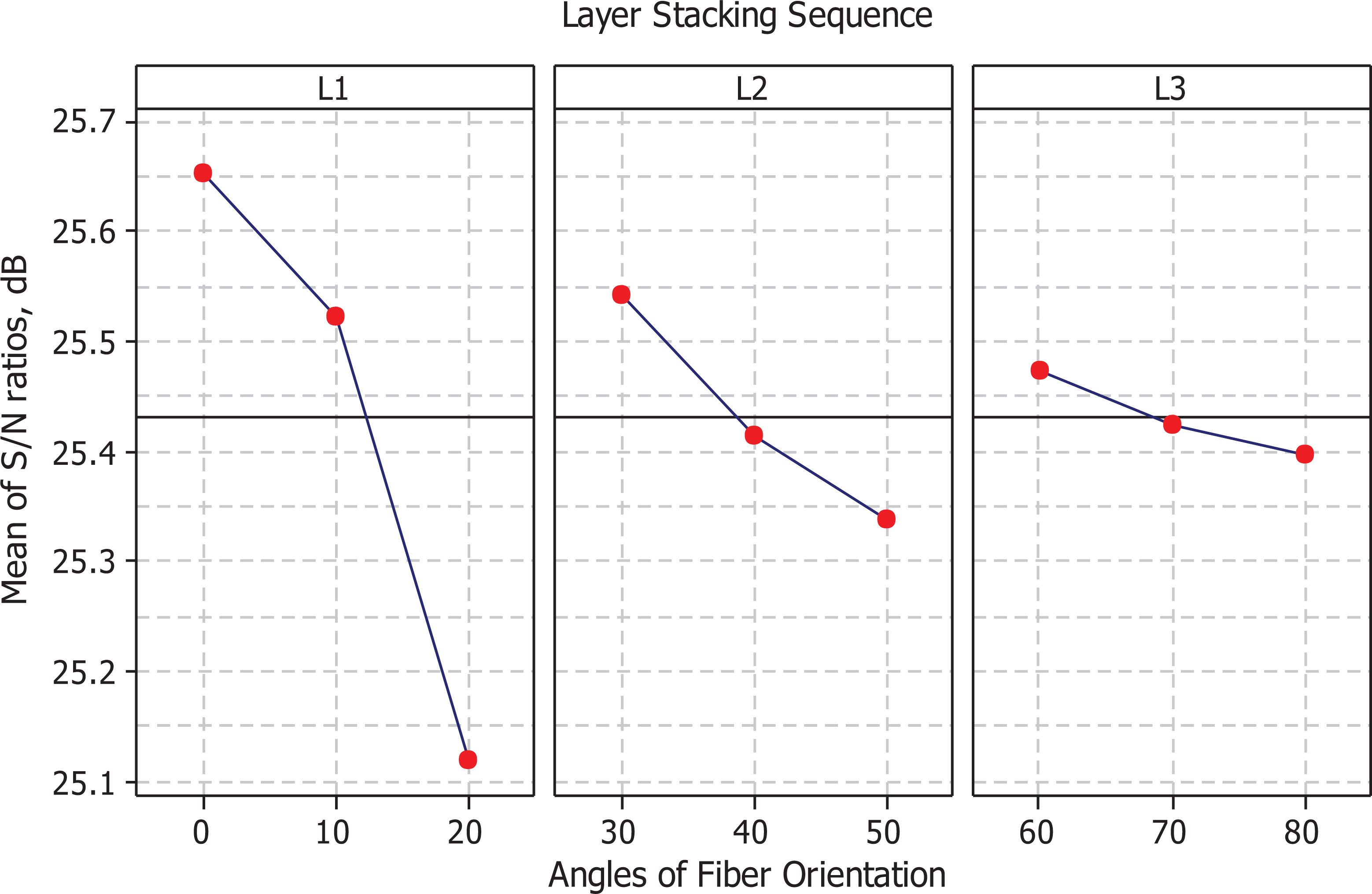
Main effects plot of S/N ratios.
It can be seen from Figure 3 that the increase of the fiber orientation angles from 0° to 80° provides the decrease of free vibration results of laminated composite beams.
Analysis of variance
Analysis of variance (ANOVA) is a statistical method. To determine significant laminates and their percent contributions on free vibration analysis, ANOVA was carried out at 95% confidence level. In the analyses, raw data for free vibration results were used. Results are tabulated in Table 4.
Analysis of variance for the fundamental frequency.

DF: degrees of freedom; SS: sum of squares; MS: variance; F: the ratio of the variance of a source to the variance of error; p: significant parameter based on 95% confidence level.
It is clear from the ANOVA results that all laminates were detected as significant control factors since p value is smaller than 0.05 data. Besides, the most effective control factors were obtained as the first and the second laminates symbolized as L1 with 85.86% contribution, the third and the fourth laminates symbolized as L2 with 12.29% contribution, and the fifth and the sixth laminates symbolized as L3 with 1.84% contribution, respectively. In Table 4, DF represents degrees of freedom, SS expresses the sum of squares, MS means variance, and F describes the ratio of the variance of a source to the variance of error. Besides, p was used to be a significant parameter based on 95% confidence level. 25
Estimation of optimum free vibration response
The estimation of the optimum response characteristics such as fundamental free vibration along with its respective confidence intervals was predicted. The optimum data of free vibration for the first mode was predicted at the optimal levels of significant variables called as L1, L2, and L3. In other words, the optimal result of fundamental free vibration characteristic was predicted assuming the effect of significant control parameters. These variables are presented in Table 4. The estimated mean of the response characteristic named as fundamental vibration can be calculated as in the equation (2). 25

where


where α = 0.05 is defined as risk and n 2 = 2 is determined to be the error data for the degrees of freedom in ANOVA. Thus, F 0.05;1;2 is calculated to be 18.5 for F ratio data depending on the 95% CI (α = 0.05). 25 V error is considered to be the error value of variance in Table 5, and it is used to be 0.00014 value. R is defined to be the sample size of confirmation experiments, and it is taken to be 3. The total number of the experimental results is taken to be (9 × 3) 27 based on Taguchi’s L9 orthogonal array in Table 3, and it is indicated to be N. Total number of degrees of freedom for significant control factors is presented to be T DOF, and it is taken to be 6. Thus, n eff is solved to be 3.857, so CICA and CIPOP are calculated to be ±0.039 and ±0.026, respectively. According to these results, the estimated confidence interval based on confirmation experimental analyses 25 is as follows:
Comparison of experimental and predicted results at 95% confidence level.

CICA: 95% confidence intervals of confirmation experiments; CIPOP: 95% confidence intervals of population.

The population for the 95% confidence interval 25 is as follows:

Confirmation experiment
To validate the results determined, the confirmation experimental analyses were conducted for fundamental free vibration using the plies with optimum levels. The average data of the characteristic was investigated, and it was compared with the estimated result. The optimal results obtained were performed in the specified range of plies. The predicted optimal data, confidence intervals and results of confirmation free vibration experiments are presented in Table 5.
Conclusions
The free vibration behavior of the laminated composite plates with functionally graded orientation angles was experimentally and statistically analyzed under clamped-free boundary conditions. The stacking sequences of the laminates and fundamental free vibration experiments were conducted using L9 orthogonal array based on Taguchi method. Analysis of S/N ratio was carried out to determine the effects of the laminates of the beams on the response characteristic. To investigate the significance of the laminates towards natural frequency for the first mode, ANOVA was performed. The following results from this numerical and statistical study were obtained: The overall mean of fundamental free vibration was found to be 18.694 Hz in the interval of selected conditions. The increase of fiber orientation angle from 0° to 80° causes a decrease in the fundamental frequency behavior. The laminated composite beam with the optimum fiber orientation angles were manufactured using the first level of ply groups such as L1, L2, and L3. The most effective control factors were obtained to be the first and the second laminates symbolized as L1 with 85.86% contribution, the third and the fourth laminates symbolized as L2 with 12.29% contribution, and the fifth and the sixth laminates symbolized as L3 with 1.84% contribution, respectively. The plies were determined to be the significant control factors at 95% confidence level according to ANOVA result. Estimated maximum fundamental frequency results for CICA and CIPOP are evaluated to be 19.473 < μ
y < 19.551 for CICA and 19.486 < μ
y < 19.538 for CIPOP, respectively.
Footnotes
Declaration of conflicting interests
The author(s) declared no potential conflicts of interest with respect to the research, authorship, and/or publication of this article.
Funding
The author(s) disclosed receipt of the following financial support for the research, authorship and/or publication of this article: The research described in this article was financially supported by the Research Fund of the Çanakkale Onsekiz Mart University [Project Number: 2791].