
Abstract
The aim of this numerical and statistical study was to investigate the buckling analysis of laminated composite plates containing functionally graded fiber orientation angles. The laminated composite plates had functionally graded fiber orientation angles based on Taguchi’s L18 (21 × 32) orthogonal array. The fiber orientation angles were considered to be control factors. Numerical analyses were performed using finite element software ANSYS. The optimum critical buckling load and the effects of fiber orientation angles for maximum data were determined using the analysis of the signal-to-noise ratio. The importance levels of laminates and their percent contribution on the buckling characteristics were calculated using analysis of variance. Regression analysis was employed to investigate the effects of control factors on buckling responses mathematically. The effects of laminate stacking sequence, mesh size, element type, mode number, and boundary condition were carried out using laminates with the optimum levels.
Introduction
Composite materials are generally used in many fields due to their superior properties, and they can be used as an alternative for metal materials. Another type of composite material is the laminated composite and it is employed in various areas for plates and beams. Modeling of laminated composite plates has been done for different analyses using various theories such as classical laminated plate theory, first-order shear deformation theory, higher-order shear deformation theory, mixed plate theory, and layerwise theory. 1 Buckling behavior is one of the important analyses, and a detailed review, 2 including the buckling analysis of plates made of laminated composites, was presented elsewhere. The finite element approach on laminated composite plates is used for different analyses in wide areas. 3 In the literature, there are many studies containing buckling analysis of composite plates and beams. Komur et al. 4 investigated the influences of elliptical/circular hole on the buckling analysis of plates made of laminated composite and they also used finite element software ANSYS. Baba 5 evaluated the buckling behavior of plates prepared using laminated composites with E-glass/epoxy under various boundary conditions such as clamped-clamped, clamped-pinned, and pinned-pinned, and effects of the circular hole and semicircular hole on the analyses were also determined. In addition, finite element software ANSYS was used. Baba and Baltaci 6 evaluated the buckling behavior of laminated composite plates designed as symmetrically and anti-symmetrically based on different cutout shapes and they also employed finite element software ANSYS. Baba 7 investigated the buckling behavior of rectangular plates prepared using laminated composites according to cutouts and finite element software ANSYS was used. Narayana et al. 8 evaluated the buckling behavior of rectangular plates designed using composites under different boundary conditions, and they also analyzed the plates containing rectangular cutout using finite element software ANSYS. Akbulut and Sayman 9 analyzed the buckling behavior of rectangular composite laminates containing a central square hole, and they also used the finite element method for analysis of critical buckling load. Baltaci et al. 10 studied the buckling behavior of laminated circular plates containing circular holes and they also used the finite element method. Kong et al. 11 investigated the buckling and post-buckling characteristics of composite plates containing a hole using numerical and experimental methods. They also used finite element analysis as a numerical method. Srivatsa and Murty 12 studied the stability of laminated composite plates having cutouts and they also used the finite element method. Larsson 13 investigated the buckling and post-buckling characteristics of orthotropic square plates with circular holes and the finite element method was also used. Crouzet-Pascal 14 investigated the buckling behavior of plates made of composite plates and structural analysis software based on finite element was used. Lin and Kuo 15 analyzed the buckling behavior of rectangular composite laminates consisting of circular holes, and they also used in-plane static loadings in the analysis. Kumar and Singh 16 evaluated the buckling and post-buckling characteristics of composite laminate made of various shaped cutouts, and they also investigated the influences of boundary conditions on responses. Thai et al. 17 presented a novel method based on a finite element approach to analyze the free vibration and buckling characteristics of plates made from laminated composites. Kahya 18 reported a study containing buckling behavior using the finite element approach and two different beam types such as laminated composite, and sandwich beams were used. Khdeir and Redd 19 evaluated the buckling characteristics of beams with cross-ply laminates and in the study, different boundary conditions were used. Wang et al. 20 analyzed the buckling behavior of generally laminated beams made of composites under various boundary conditions. They also used the isogeometric finite element approach. Karama et al. 21 presented the study about analyses of bending, buckling, and natural frequency of laminated composites, and they also used a transverse shear stress continuity model in their study. Aydogdu 22 investigated the buckling behavior of beams designed using cross-ply laminates under different boundary conditions according to Ritz method. Matsunaga 23 evaluated the vibration and buckling characteristics of beams made of multilayered composites and higher order deformation theories were used in the study. Song and Waas 24 evaluated influences of shear deformation on analyses of buckling and natural frequency of beams made of laminated composites. Timarci and Aydogdu 25 analyzed the buckling behavior of square plates with symmetric cross-plies and analyses were done under different boundary conditions. Panda and Ramachandra 26 studied the buckling behavior of rectangular plates prepared using composites under different boundary conditions. As can be seen from the literature described, there are many studies with buckling analysis of composite plates and beams using finite element and experimental methods. In this study, numerical and statistical buckling analysis of laminated composite plates was investigated. The laminates have functionally graded fiber orientation angles. Numerical buckling analyses were performed using finite element software ANSYS Parametric Design Language (APDL) according to L18 (21 × 3 2 ) orthogonal array based on Taguchi method.
Materials and methods
In the analyses, a square laminated composite plate made of glass fiber-reinforced polymer (GFRP) composites was used. The plates have 12 layers and the ply orientation distribution in the plate thickness was designed. A side length and thickness of the plates were considered to be 204.6 mm and 2.11 mm, respectively. 27 Material constants of GFRP square laminated plates are presented in Table 1.
Material constants. 27

Laminate stacking sequences of the plates were conducted using Taguchi’s L18 (2 1 × 3 2 ) orthogonal array. The orthogonal array has 18 runs and 3 control factors. The first control factor has two levels whereas the other control factor has three levels. The fiber orientation angles for each four laminates were considered to be control factors. In other words, the first four laminates were determined as the first control factor with two levels. The second four laminates were considered to be the second control factor with three levels. The third four laminates were assumed to be the third control factor with three levels. Thus, fiber orientation angles of four laminates were used to be control factors. Fiber orientation angles have changed from 0° to 70°. The control factors and their levels are tabulated in Table 2.
Control factors and levels.

To obtain the laminated composite plates with the optimum control factors for the maximum critical buckling loads, “Larger is Better” quality characteristic was used, and these statistical analyses were carried out using Minitab 15 software. 28 The quality characteristic was presented in equation (1). 29

where n is determined as the number of numerical analyses in a trial and y i denotes ith data analyzed. Numerical results obtained for critical buckling based on the first mode were converted to signal-to-noise (S/N) data.
Finite element analysis
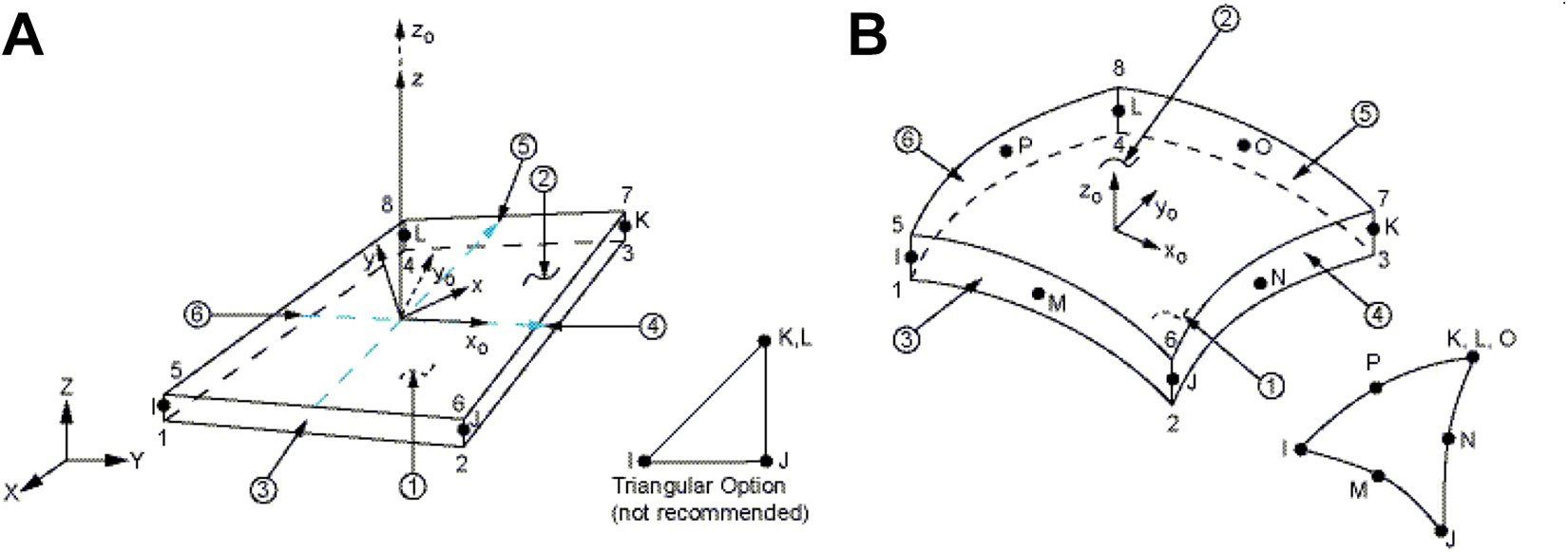
Numerical analyses were performed using finite element software ANSYS Mechanical APDL. 30 Each plate was modeled using ANSYS according to L18 orthogonal array based. The plates made of nine different laminated composites were modeled. In the software, SHELL281 and SHELL 181 element types were used. SHELL181 31 is named as a four-node structural shell containing six degrees of freedom for each node: translations based on the x-, y-, and z-directions, and rotations as regard the x-, y-, and z-axes. Besides, SHELL281 31 element is used to be an eight-node including six degrees of freedom according to each node: translations for the x-, y-, and z-axes, and rotations as regard the x-, y-, and z-axes. Both elements are convenient using analyzing thin to moderately thick shell structures. The geometries of the element type such as SHELL181 and SHELL281 are shown in Figure 1. 31
SHELL281 element type was used to determine the laminated composite plates with optimum levels in the Taguchi method. Analyses based on L18 orthogonal array in finite element software were carried out using 100 × 100 mesh size. Mesh type was selected to be free mesh. Block Lanczos was used as the extraction method. The problem dimensionality was considered to be 3D and a globally assembled matrix was assumed as symmetric. The compressive load with 1 N/mm value was applied to the x-direction of the plates. Direction 0° denotes that the ply fiber is laid parallel to the length (x-direction). In addition, the plates with left edge clamped (C) and remaining edges free (F) conditions were used to investigate the optimum results for maximum critical buckling behavior. The boundary conditions are shown in Figure 2.

Plate with C-F-F-F boundary conditions.
Results and discussions
Numerical analyses were conducted to investigate the effect of fiber orientation angles of plies over the output buckling characteristics. Eighteen finite element analyses were performed using Taguchi experimental design methodology and raw data obtained based on ANSYS software were analyzed using Minitab 15 statistical software. Analyses were performed L18 orthogonal array. The critical buckling load results for the first mode and their S/N ratio values are presented in Table 3.
Results of finite element and S/N ratios.

S/N: signal-to-noise; P value (Force).
Determination of optimum levels
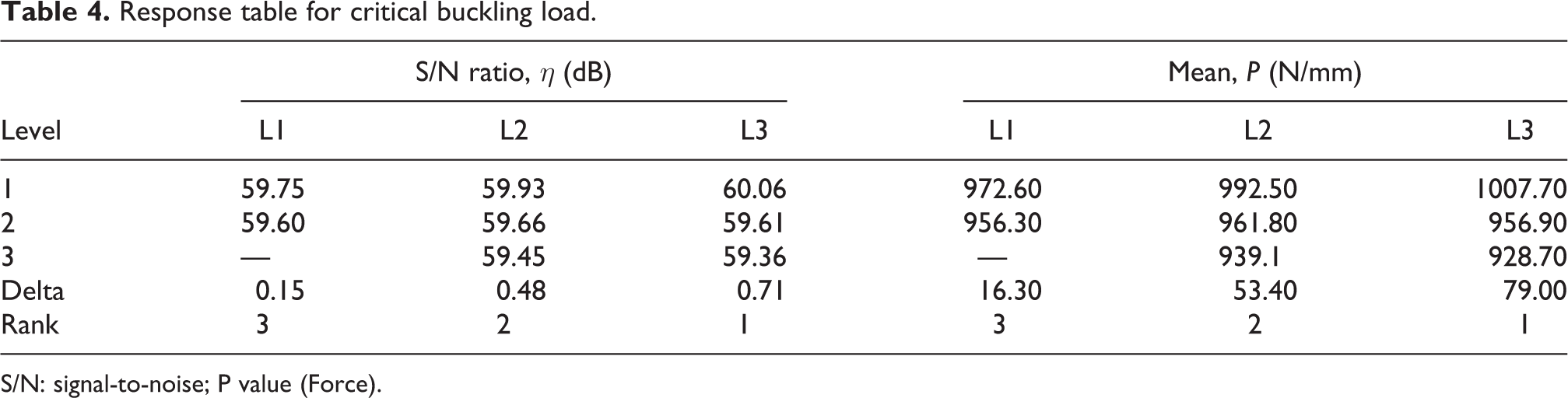
To determine the maximum critical buckling load for first mode using laminated composite plates with functionally graded fiber orientation angles, the average values of finite element results of the critical buckling loads for each laminate such as L1, L2, and L3 at levels 1, 2, and 3 for numerical data and S/N data are analyzed using statistical software Minitab 15. The average results calculated for numerical and S/N ratio are presented in Table 4.
Response table for critical buckling load.
S/N: signal-to-noise; P value (Force).
To select the optimum levels based on “Larger is Better” characteristic, the maximum values of the average S/N ratio and raw data for each control parameter at each level were used. As can be seen from Table 4, the optimum levels of the control parameters were determined as the first levels for L1, L2, and L3. Minitab software assigns ranks depending on delta values; rank 1 to the first highest delta result, rank 2 to the second highest data, and so on. The rank and the delta values present that L3 has the greatest influence on the critical buckling loads for the first mode and is followed by L2 and L1 in that order.
Effects of fiber orientation angles
The average S/N ratio of the response characteristics based on each variable at various levels was calculated using finite element results. The results are tabulated in Table 4. To see the effect of fiber orientation angles of plies on the buckling analysis for the first mode, the main effects of the variables for S/N data were plotted as shown in Figure 3.

Effects of fiber orientation angles.
As can be seen from Figure 3, the critical buckling loads for first mode decrease with the increase of degrees of fiber orientation angles from 0° to 70° according to each ply.
Analysis of variance
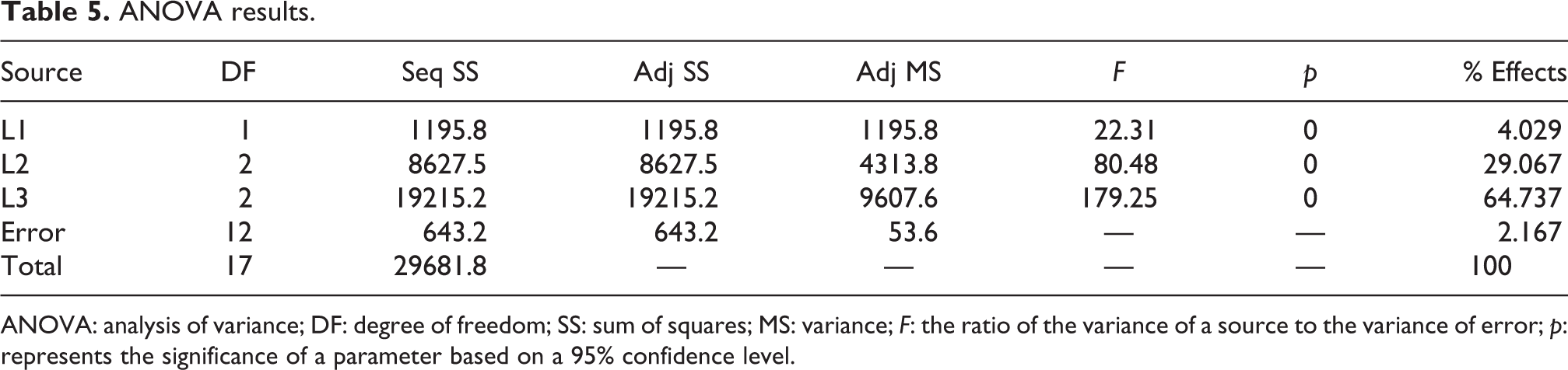
Analysis of variance (ANOVA) is a statistical technique and their associated prediction procedures utilized to examine the differences between group means in a model. In this present study, the level of importance of the composite plies used as control factors and their percent contributions towards the critical buckling behavior of the laminated composite plates with functionally graded fiber orientation angles were analyzed using ANOVA. The analysis was carried out at a 95% confidence level, and it was used numerical buckling results for the first mode. ANOVA results based on R 2 = 97.83% and R 2 (adj) = 96.93% are tabulated in Table 5.
ANOVA results.
ANOVA: analysis of variance; DF: degree of freedom; SS: sum of squares; MS: variance; F: the ratio of the variance of a source to the variance of error; p: represents the significance of a parameter based on a 95% confidence level.
As can be seen from Table 5, the most effective control factors were calculated as L3 with 64.737% effect, L2 with a 29.067% effect, and L1 with a 4.029% effect. In other words, the increase of fiber orientation angles provide a decrease in the critical buckling behavior of the laminated composite plates. Thus, the decrease of the fiber orientation angles from 70° to 0° causes high strength for the plates. The percent error of the analysis was found to be 2.167% in Table 5. Also, the control factors named L1, L2, and L3 are determined to be the significant parameters on the responses since p value is lower than 0.05 data. In Table 5, DF indicates degrees of freedom, SS refers to the sum of squares, MS expresses variance, F denotes the ratio of the variance of a source to the variance of error, and p represents the significance of a parameter based on a 95% confidence level.
Estimation of optimum results
The optimal data of the response characteristic called the critical buckling load along with their respective confidence intervals were analyzed. The optimal result of response characteristic was estimated considering the influence of the meaningful control parameters only. Thus, the optimum value of the critical buckling load for the optimal levels of meaningful variables was calculated using L1, L2, and L3 according to ANOVA. The estimated mean of the critical buckling load can be calculated using equation (2). 29

where


where n
2 = 12 denotes the error value for the degree of freedom from ANOVA data and α = 0.05 presents the risk. Thus,

The population based on the 95% confidence interval 29 is:

The finite element and estimated results for the optimal critical buckling load for confidence intervals are tabulated in Table 6.
Finite element and predicted results.

CICA: 95% confidence intervals of confirmation analyses; CIPOP: 95% confidence intervals of population.
Comparison of finite element and predicted results
To analyze the residual and percent error between finite element and Taguchi predicted results, the numerical buckling load results based on L18 orthogonal array were compared with predicted results using equation (2). The average results of critical buckling loads for each control factor at each level were used for Taguchi predicted results. These data were taken from Table 4. The residual and percent error for both results are tabulated in Table 7.
The differences between numerical and predicted results.
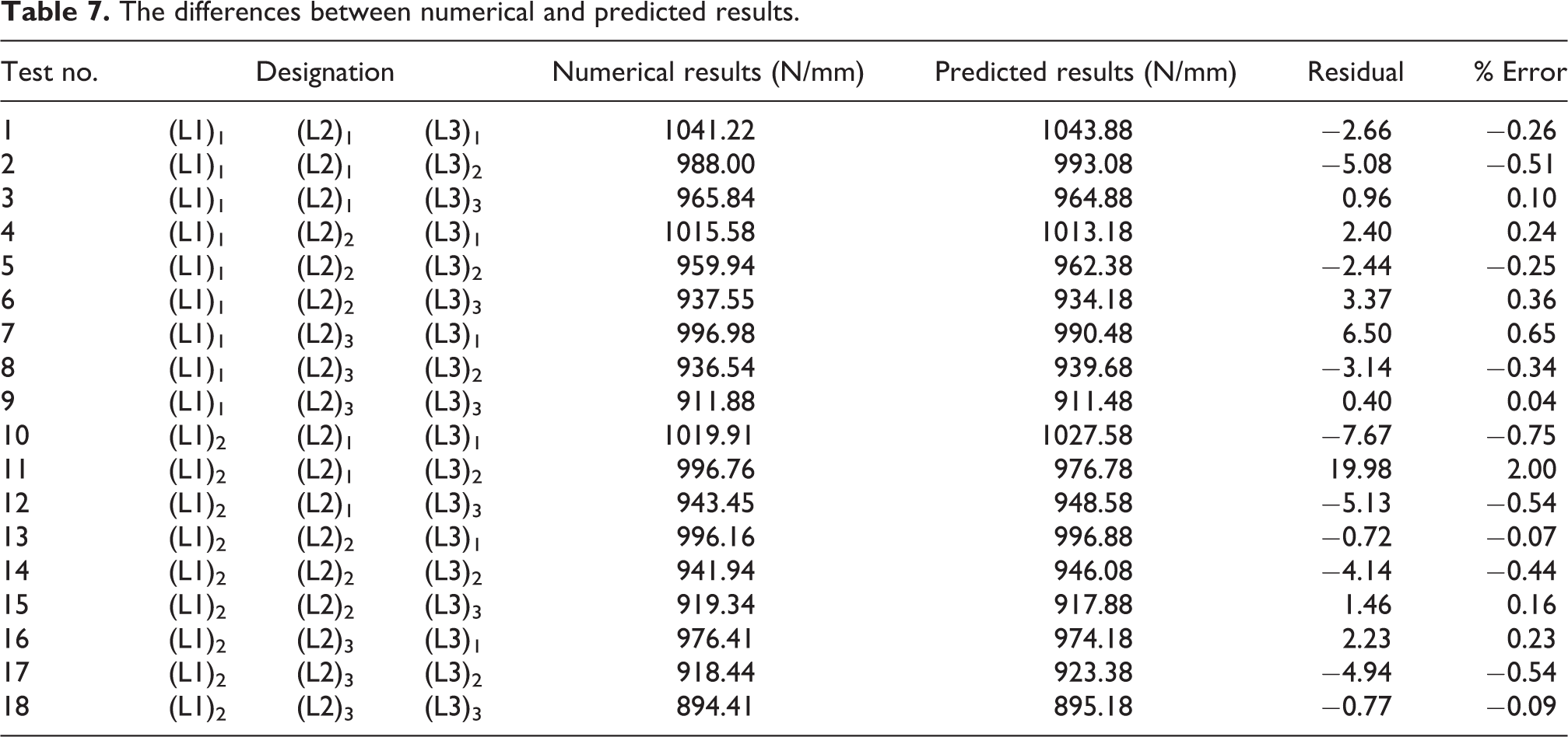
As can be seen from Table 7, the predicted results obtained using the Taguchi method were closer to numerical buckling loads for first mode. The maximum difference was obtained using eleventh analysis whereas the minimum difference was determined for nineteen analysis.
Regression analysis
To see the effects of control factors such as L1, L2, and L3 on the critical buckling behavior of the laminated composite plates, regression analysis was used. Regression equation based on R 2 = 95.9% and R 2 (adj) = 95.0% was given in equation (6).

According to equation (6), the plies called L1, L2, and L3 have negative illustrates on the critical buckling loads. In other words, the increase of fiber orientation angles of the plies leads to a decrease of the critical buckling load for the first mode. ANOVA based on regression analysis are tabled in Table 8.
ANOVA for regression analysis.
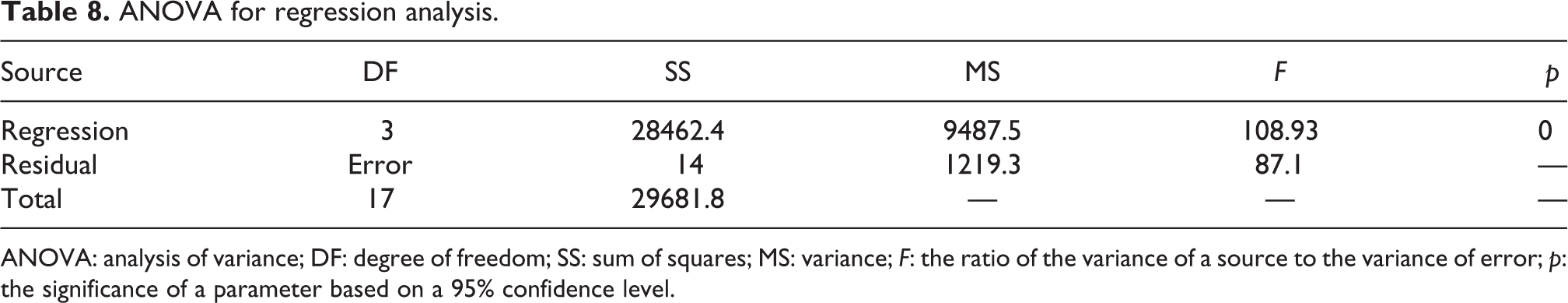
ANOVA: analysis of variance; DF: degree of freedom; SS: sum of squares; MS: variance; F: the ratio of the variance of a source to the variance of error; p: the significance of a parameter based on a 95% confidence level.
Effect of laminate-stacking sequence
To understate the effect of the laminate stacking sequence, the laminates composite plate with optimum levels was used according to the Taguchi method. This plate was encoded to be (L1)1-(L2)1-(L3)1. Different arrangements of these plies and their critical buckling load results for the first mode are tabulated in Table 9.
Comparison of optimum laminates.

S/N: signal-to-noise.
It was investigated from Table 9 that the critical buckling behavior is sensitive to the orientation of the outermost layers of the plies. In other words, the outermost plies with small angles increase the critical buckling loads. Laminated composite plate with (L1)1-(L3)1-(L2)1 showed higher critical buckling load as compared to that of plates with (L1)1-(L2)1-(L3)1 and (L2)1-(L1)1-(L3)1. Thus, the laminate stacking sequence has significant effects on the critical buckling analysis of the laminated composite plates. Laminate stacking sequences of the plate with (L1)1-(L2)1-(L3)1 and (L1)1-(L3)1-(L2)1 are shown in Figure 4.

Laminate-stacking sequence: (a) (L1)1-(L2)1-(L3)1 and b) (L1)1-(L3)1-(L2)1.
Effect of mesh size
To observe the effects of mesh size on the responses, finite element analysis containing different mesh sizes was performed using ANSYS software. In the analyses, two types of plates were used. One of these is the plates with optimum levels based on the Taguchi method and the other is the plate made of the different combination of the optimum levels. Types of the plates and their critical buckling results for different mesh sizes are presented in Table 10.
Critical buckling loads for different mesh sizes.

As can be understood from Table 10, the increase of the mesh sizes increases the sensitivity of analysis for both laminated composite plates. The increase in the number of mesh increases the precise calculation.
Effect of element type
To determine the effects of the element types in finite element software ANSYS on the buckling analysis for the first mode, two type elements such as SHELL181 and SHELL281 were used. Analyses were carried out for first mode and same mesh size. In finite element analysis, only element type was changed, and the other parameters were used as constant. The critical buckling loads for types of elements are presented in Table 11.
Buckling results for SHELL181 and SHELL281.

It is clear from Table 11 that the numerical result obtained using the SHELL281 element type is smaller than the finite element result using SHELL181 for both plates. That situation can be explained by different properties and sensitivities of the elements. SHELL181 31 is called as a four-node structural shell containing six degrees of freedom for each node: translations based on the x-, y-, and z-directions, and rotations as regard the x-, y-, and z-axes, but SHELL281 31 element is used to be eight-node including six degrees of freedom according to each node: translations for the x-, y-, and z-axes, and rotations as regard the x-, y-, and z-axes. Thus, analyses performed using the SHELL281 element is more sensitive.
Effect of mode
To investigate the effects of the modes on buckling characteristics, various combinations of plies with optimum levels were used. Modes were changed from 1 to 5 for each plate. The critical buckling load results for different mode numbers are presented in Table 12.
Critical buckling loads for different modes.

It can be seen from Table 11 that the increase of the mode for the buckling analysis leads to the increase of the critical buckling loads of laminated composite plates.
Effect of boundary conditions
To evaluate the effects of the boundary conditions such as C-F-F-C, C-F-F-P, P-F-F-P, and C-F-F-F, laminated composite plates made of plies including the optimum fiber orientation angles were used. In the analysis, C-F-F-C was defined as left and right ends clamped and remaining edges free. C-F-F-P was used as left edge clamped, right edge pinned, and remaining edges free. P-F-F-P was considered as left and right edge pinned, and remaining edges free. C-F-F-F was assumed as left end clamped and remaining edges free. The results for critical buckling analysis using the different boundary conditions were demonstrated in Table 13.
Buckling results for various boundary conditions.
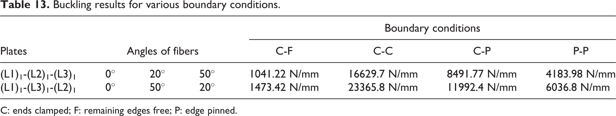
C: ends clamped; F: remaining edges free; P: edge pinned.
As can be seen from Table 13, the maximum critical buckling results for the first mode were obtained using laminated composite plates with C-F-F-C, C-F-F-P, P-F-F-P, and C-F-F-F boundary conditions.
Conclusions
In this finite element and statistical study, the buckling behavior of the laminated composite plates with functionally graded fiber orientation angles was investigated based on Taguchi’s L18 orthogonal array. The laminated composite plates with optimum levels were evaluated using analysis of S/N ratio and significant control parameters and their percent contributions were carried out using ANOVA. Regression analysis is developed to study the influence of control factors on buckling responses mathematically. The influences of laminate stacking sequence, mesh size, element type, mode number, and boundary condition are carried out using laminates with the optimum levels. The conclusions from this numerical and statistical study are summarized as follows. The overall mean of the critical buckling load for the first mode is found to be 964.46 under clamped-free boundary conditions according to the L18 orthogonal array. The optimal result for the maximum buckling load is obtained using plies with first levels. The increase of the fiber orientation angles of plies from 00 to 700 provides the decrease of the critical buckling loads. The four plies such as L1, L2, and L3 are determined as significant control parameters since p value is smaller than 0.05 for a 95% confidence level. The most affected plies are observed as L3 with a 64.737% effect, L2 with a 29.067% effect, and L1 with a 4.029% effect. Predicted the maximum critical buckling loads at CICA and CIPOP are solved to be 1025.455 Finite element and predicted buckling loads are found to be 1041.22 N/mm and 1043.88 N/mm, respectively. According to regression analysis, the plies named as L1, L2, and L3 have negative effects on the critical buckling loads. The laminate stacking sequence plays an important role in responses and the outermost plies with small angles increase the critical buckling loads more than innermost plies. The mesh size affects the sensitivity of buckling analysis directly. The element type in finite element analysis has significant effects on the buckling analysis. The increase of the modes in the buckling analysis causes the increase of the critical buckling loads. The highest buckling loads are obtained using C-F-F-C, C-F-F-P, P-F-F-P, and C-F-F-F boundary conditions, respectively.
Footnotes
Declaration of conflicting interests
The author(s) declared no potential conflicts of interest with respect to the research, authorship, and/or publication of this article.
Funding
The author(s) received no financial support for the research, authorship, and/or publication of this article.