
Abstract
Recently, the incorporation of several different types of fibers into a single matrix has led to the development of superior hybrid composite properties at a cheaper cost. Fiber hybridization is one of the active strategies to toughen composites and improve impact damage resistance. However, the extraordinary high strength and stiffness of the carbon fiber as well as its lower damage tolerance make it more susceptible under the impact loading. This article mainly aims to improve impact damage resistance of carbon fiber pipes through fiber hybridization strategy with glass fibers under low-velocity impact. The composite pipes reinforced with thin internal liner of high-density polyethylene were fabricated through filament winding technology. Eight pipe configurations with different stacking sequences and fiber content ratios with a constant winding angle of
Introduction
Fiber-reinforced polymer (FRP) composites are increasingly being used in many industrial fields especially in pipes and cylindrical tanks, due to their superior mechanical and physical properties. These composite materials are exposed to various types of damages due to impact loading and other machining operation which can cause an invisible damage level.1-3 Specifically, synthetic fibers are irreplaceable fibers in the composite components especially that require superior strength and stiffness such as aircraft structures and high-pressure vessels. Thus, many investigations have been conducted for the filament-wound composite pipes using the synthetic fibers under different mechanical phenomena.4,5
Hybrid composite pipes consisting of two or more types of fiber reinforced with a specific type of epoxy have many advantages over the single fiber fabrication. These hybrid products exhibit improved mechanical properties, possess higher toughness, greater flexibility, and are produced at relatively low cost and/or weight. 6 General vulnerability through the thickness of composite structures as well as their low compressive strength combined with the barely visible failure modes are of great concern under impact loadings. In this regard, low-velocity impact of foreign particles on the composite structures most of the time constitutes a critical situation. Specifically, impact of small mass with high velocity produces different damage effects on the composites than a large mass with low velocity for a similar kinetic energy of the impactor. 7 In addition, these damages can significantly reduce the strength and stability of structures resulting in a catastrophic failure. Fiber breakage is the most critical failure mode which normally occurs in the composite pipes and cylinders under critical impact loading and causes component degradation. 8
The knowledge of impact response of cylindrical pipes can provide a good basis for establishing the impact behavior of composite pressure cylinders.9,10 Thus, this study has been conducted primarily to examine the impact response of different configurations of hybrid pipes under low-velocity impact energies. Accordingly, specimens that have high impact resistance and less damage severity would be selected for the fabrication of type IV hybrid composite pressure vessels. Therefore, the inclusion of internal liner of high-density polyethylene (HDPE) in the composite pipes used in this study was intended to simulate the impact response of cylindrical section of type IV composite pressure vessels. Normally, composite pressure vessels are made from carbon fibers which exhibit excellent burst properties but are more susceptible under impact loading. Specifically, low toughness property, low damage tolerance, and low ultimate strain are the main problems faced by the carbon fiber. In addition, the manufacturing cost of carbon fiber is much higher than glass fiber.
Different efforts were considered in the literature to detect damage, predict residual strength, and improve impact damage resistance on pipes and pressure vessels under low-velocity impact. One of these efforts to reduce the impact damage on the composite pressure vessel was undertaken by Lee and Kang 11 through the application of protective materials on the vessel surface. The preservative materials used were styrene-butadiene rubber, glass/epoxy and Kevlar/epoxy laminates with a vessel made of carbon/epoxy as a base material. Experimental impact tests were conducted for different impact energy levels of 30, 60, and 90 J. Results showed that glass/epoxy laminates are the best combination for improving damage resistance while the rubber laminates are the least effective combination.
Alderson and Evans 12 studied the impact-induced damage effects under quasi-static and low-velocity impact loading. Thin filament-wounded composite tubes fabricated from E-glass/epoxy at ±55° winding angle were considered. Results showed that delamination and local crushing were always present as the primary modes of induced damage during low-velocity impact tests. Kara et al. 13 experimentally investigated filament-wound glass/epoxy tubes for three impact energy levels under low-velocity impact. The tubes used were of 72 mm inner diameter with winding angle of (±55°)3 and average thickness of 2.375 mm. The impacted specimens were subjected to internal pressure loading up to 32 bars during low-velocity impact testing to predict the failure of normal and prestressed tubes. No fiber breakage was observed from the impacted specimens. However, delamination and debonding failure modes were observed. Moreover, results exhibited that larger damage area and reduction of burst pressure were observed for the normal tubes than the prestressed tubes for each level of impact energy.
Alshahrani et al. 14 studied low-velocity impact effects of E-glass-fiber-reinforced epoxy pipes numerically and experimentally. The pipe used was wrapped using eight layers of laminates at ±54.5° with a length of 300 mm and 150 mm inner diameter. Two thicknesses of pipe were considered, 4.5 and 6 mm, for variable applied impact energies of 12, 35, 80, and 110 J. Generally, under low impact energies, matrix cracking and delamination were observed, whereas fiber breakage occurred at intermediate to high energies. It was found that a full penetration occurred under the impact energy of 80 J for a pipe thickness of 4.5 mm. Recently, Rafiee et al. 15 showed the importance of theoretical and numerical analyses to analyze low-velocity impact and induced failure modes of composite cylinders. Theoretical approach using the layerwise theory was considered to determine stress/strain components in order to predict impact failure through the failure criteria. The results revealed that the theoretical solution employed was more accurate than finite element analysis to investigate the low-velocity impact of composite cylinders.
Despite several researchers have analyzed the impact behavior and induced damage on the FW pipes and cylinders, there is still lack of studies focused on hybrid composite pipes reinforced with a polymeric liner of HDPE under low-velocity impact testing. Gemi et al. 16 experimentally analyzed the hybrid composite pipes of carbon–glass/epoxy fabricated with filament winding process under low-velocity impact loading. Prestressed specimens were loaded at 4, 16, and 32 bar internal pressure and tested for different impact energies of 5, 10, 15, and 20 J. Delamination and matrix cracking at the outer surface of the hybrid pipes were the main observed failure mechanisms. Results indicated that the severity of damage was decreased with increasing internal pressure under the same impact energy. Recently, many investigations have been successfully studied by the same author. Gemi 17 studied the effect of stacking sequence on low-velocity impact of filament-wound composite pipes under internal pressure. The carbon–glass hybrid pipes of ±55° winding angle were tested at different energy levels of 5, 10, 15, and 20 J under 32 bar internal pressure. The results showed that different damage patterns have been observed except of fiber breakage for the applied impact energies. Also, the effect of impact loading on the fatigue behavior has been investigated for filament-wound hybrid composite pipes under internal pressure by Gemi et al. 18
The current study differs from the work of Gemi et al. 16 in many aspects such as fiber orientation of pipes, impact energy, prestressed loading as well as the presence of plastic liner used in our study. From the other aspect, most of the studies in the literature focused on analyzing pipes with ±55° winding angle including the work of Gemi et al. 16 Meanwhile, there is a need to combine helical and hoop winding layers which represent the gap in the analysis of composite pipes as reported by Rafiee. 19 At the same instance, this type of winding gives the pipes more consolidation to resist internal/external pressure due to the presence of 90° layup as it represents a normal practice in the production process. More recently, Mohamad Hamdan et al. 20 showed that the natural hybrid composites could be an important alternative for the synthetic composites. In this study, the flexural and impact performance of hybrid woven jute–roselle fiber-reinforced composites were significantly high as compared to the other hybrid samples. Irfan et al. 21 studied the hybridization effects of short glass–carbon fiber-reinforced vinyl ester and fiber orientation on the bending properties. The results showed a positive effect of bending properties for all the hybrid composites with longitudinal direction of fibers as compared to the random orientation.
In the present study, the main objective is to improve impact damage resistance of carbon fiber pipes through the fiber hybridization strategy by adding the glass fibers. Eight pipe configurations were fabricated based on different stacking sequences and fiber content ratios and tested for two levels of impact energies, 50 and 100 J, to predict the most critical impact damage.
Experimental procedure
Materials and specimen preparation
The continuous filament glass and carbon roving fibers were used in this study as the reinforced materials in epoxy resin. Continuous filament fibers of E-glass and Toray T700 carbon fibers were supplied by China National Building Materials and Equipment, China. The mechanical properties of the utilized fibers and epoxy resin are shown in Table 1, as received from the suppliers.
Mechanical properties of the fibers and resin.

The hybrid composite pipes fabricated using filament winding process were composed of eight layers with constant winding angles of
Stacking sequence arrangement of carbon/glass coupon specimens.a

CF: carbon fiber; GF: glass fiber.
a The sequence is from the pipe inside to outside.
Manufactured hybrid pipes had an internal diameter of 85 mm and total length of 1000 mm with an average thickness of 5 mm. A thin internal liner of HDPE, 1.75 mm in thickness, was used for all the fabricated pipes. The plastic liner does not provide any reinforcement to the pipe structure but instead it is used for the purpose of chemical barrier. The calculated fiber volume fraction was 48%, determined by the ignition loss test based on the standard ASTM D2584 through the knowledge of specimens’ weights before and after burning as well as the knowledge of both fiber and matrix densities. The fiber volume fraction (Vf) and matrix volume fraction (Vm) were calculated based on formulations (1) and (2) below


where Mi, Mf, ρc, ρr, and ρm denote the initial mass of the specimen in grams, final mass of the specimen after burning in grams, density of the specimen in g/cm3, density of the reinforcement in g/cm3, and density of the matrix in g/cm3, respectively.
The curing process was carried out at 80°C for 2 h and post-cured at 120°C for 2 h. Finally, the cutting process was done to obtain specimens with final length of 125 mm. The fabricated composite pipes and corresponding cut specimens are shown in Figure 1(a) and (b).
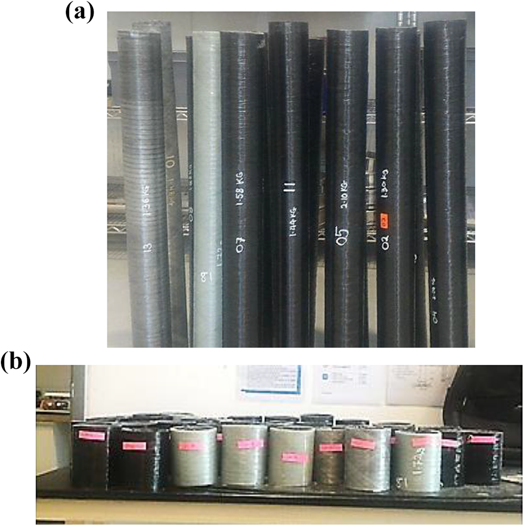
(a) Manufactured cylindrical composite pipes and (b) cut samples.
Experimental impact test
Instrumented drop-weight impact machine (IMATEK, model C3008, Gloucester, Brockworth, UK) was used to perform low-velocity impact tests on the hybrid composite pipes according to the ASTM D2444-99 and ASTM D7136/D7136M-12 standards. Figure 2 shows the equipment of drop-weight impact and the fixation tool for the impact test. A special clamping fixture was manufactured and used in the drop-weight instrumented machine instead of the original clamping for the laminated plates. Specimens were fixed to the V-shape through a bolt and nut arrangement to hold and restrict the sample’s movement. Non-pressurized samples have been subjected to two levels of impact energies, 50 and 100 J, at the room temperature to predict the critical induced damage of specimens.
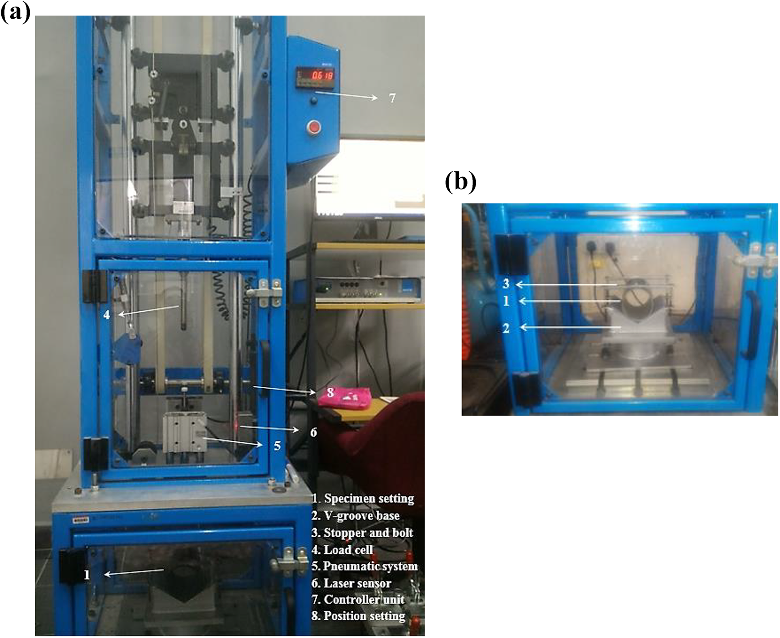
(a) Instrumented drop-weight impact machine and (b) clamping fixture.
From the literature, prestressed specimens exhibited positive response in terms of impact damage resistance. The damage effects will be improved significantly when pipes are subjected to internal pressure loading as verified by other investigations.16,22,23 Consequently, the focus was on how to increase the impact resistance while improving the energy absorption mechanism of non-prestressed pipes during impact test. This contribution will definitely enhance the performance of these components when subjected to internal pressure loading. The selected impact energies were applied by adjusting the falling height of the impactor to 1 and 2 m to achieve 50 and 100 J, respectively. A hemispherical impactor with a diameter of 16 mm and total striker mass of 5.101 kg including force transducer and the crosshead was used to conduct low-velocity impact tests. An anti-rebounding system is equipped in the test instrument to prevent repeated impact of the impactor on the specimen after the test is completed. Each test condition was repeated three times and their average results were considered. The output results captured from the impact test were the force–time (F-T), force–displacement (F-D), and energy–time histories for the applied impact energies.
Results and discussion
Impact response at low energy loading
Low-velocity impact tests for the carbon/glass pipe configurations were performed at impact energy of 50 J. Maximum impact force, maximum deformation, and energy absorption capability as well as severity of damage monitored from the tests were the main parameters adopted to evaluate the impact resistance. The absorbed energy by the specimens is an important parameter to assess the impact resistance and induced damage as it also represents the toughness of composite materials. 24 Absorbed energy is computed numerically by considering the area under the F-D curves and compared with the value taken from the impact instrument. From the impact analysis, the rebounding-type curves were noticed for all tested cases, observed clearly from the F-D graphs. Figure 3 shows the F-D curve of the reference carbon and glass FRP pipes at 50 J impact energy. Although the carbon sample showed having slightly higher maximum impact force with lower maximum displacement than glass sample, the latter gave higher energy absorption. As expected, the carbon fiber sample is more fragile than the glass fiber sample, so it resisted the impact without showing further damping on the sample (low toughness property). The glass fiber specimen exhibited more damage area than carbon fibers. Thus, more increased cracks and delamination area were observed on the glass specimens. It is remarkable that the damage in the pure glass sample was in the form of delamination damage compared to pure carbon sample. This, in turn, can increase the energy absorption capacity of interlaminar damage rather than intralaminar damage, which explains the increased energy absorption on the glass sample. The fiber breaking failure mode can also be observed on the glass and carbon specimens.

F-D curves for the reference carbon and glass FRP pipes under 50 J of impact energy.
Generally, all the F-D and F-T curves captured from the impact tests are noticed of having large fluctuations especially on the ascending part of load–displacement curves. Similar behavior of these fluctuations was observed on the impact curves of the analysis by Ribeiro et al. 25 although relatively low applied impact energy (31 J) was considered in their study. Different failure mechanisms such as delamination initiation between several layers and its propagation can cause further oscillations in the F-T and/or F-D curves. In addition, composite materials damping behavior and large range of frequencies during impact tests may contribute to this response. Moreover, the absence of internal pressure on the specimens subjected to impact loadings highly affected the bending rigidity and accumulative damage of pipe samples. Thus, the dramatic sharp drop seen on the figures was due to the extensive damage experienced by the specimens. On the contrary, the impact tests conducted for the prestressed samples from other investigations exhibited smooth oscillations, recorded through the F-D history. In addition, the improvement in impact damage behavior on the specimens was also observed for prestressed cases.13,16
Impact characteristics such as peak force, maximum displacement, impact duration time, and energy absorption capacity for the composite specimens were determined and presented in Table 3 under the impact energy of 50 J. The impact behavior for the hybridized pipes of 50:50 carbon–glass fibers composition is represented in Figure 4. Specimens of glass fibers on the exterior side (H1) and alternative configuration of carbon–glass fibers (H3) showed higher maximum impact forces with a relatively large deformation noticed on H1 samples.
Summary of impact parameters for composite pipes subjected to 50 J of impact energy.

C: carbon; G: glass; CF: carbon fiber; GF: glass fiber.
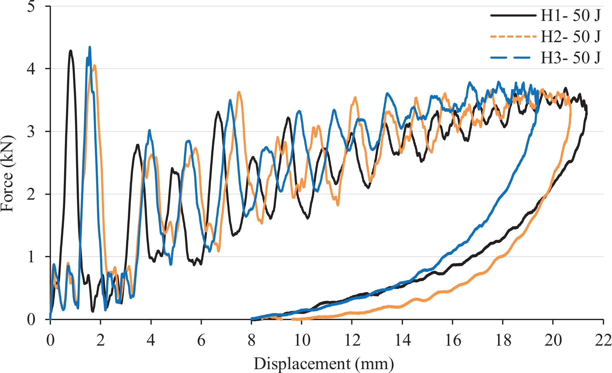
F-D curves for the hybrid pipes of 50:50 fiber content ratio under 50 J impact energy.
An improvement of the damage severity was observed on the specimens H1 and H3 as a result of recorded energy absorption values. A similar finding has been observed by Gemi et al. 17 in terms of the damage formation although relatively low impact energies considered in their study. As such, the stacking sequence of glass fiber at the exterior showed better damage response which is similar to the hybrid configuration H1 used in our study under 50 J energy. Furthermore, the more ductile fibers on the impacted side and alternative samples showed better impact resistance which is consistent with the literature.26,27 Moreover, there is no remarkable difference between the hybrid pipes in terms of energy absorption mechanism, but the improvement was significantly noticeable as compared with the carbon fiber samples. Thus, the addition of 50% glass fibers to the carbon fibers improved the energy absorption capability by 11.7%, 17.9%, and 14.3% for the hybrid pipe configurations H1, H2, and H3 as compared with the carbon fiber specimen, respectively.
Similar scenario was observed from the F-D graphs for the carbon–glass hybrid pipes with 75:25 fiber content ratio. Small differences were noticed in the peak impact force, maximum displacement, and energy absorption parameters during the impact response as shown in Figure 5. Also, different failure modes appeared on the impacted specimens such as matrix cracks, delamination, and fiber fracture as it is evident through the large oscillations spotted from impacted curves. The increased percentage of carbon fibers led to further damage observed on H4 and H6 pipe configurations as a result of the increased energy absorption capacity.

F-D responses for different pipe stacking sequences at 75:25 fiber content ratio subjected to 50 J energy.
Impact behavior at high energy loading
Similar pipe configurations were also tested under high impact energy of 100 J to predict the impact response and induced damage under this critical energy. Generally, the impact parameters such as the maximum impact force, contact time, maximum deformation, and absorbed energy described in Table 4 are higher at impact energy of 100 J as compared to 50 J.
Summary of impact parameters for the composite pipes under 100 J of impact energy.
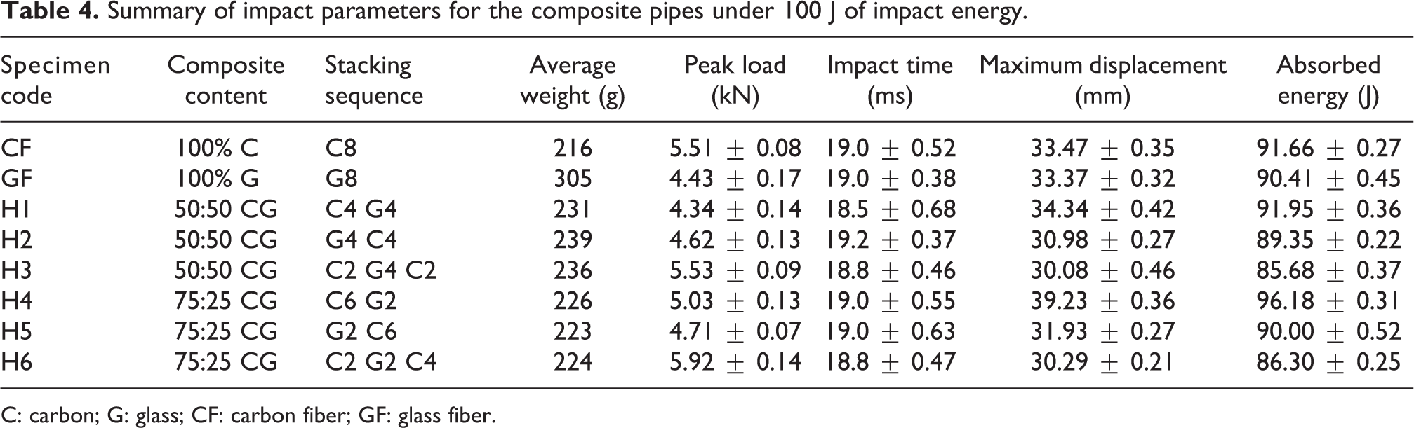
C: carbon; G: glass; CF: carbon fiber; GF: glass fiber.
Reference carbon FRP pipes showed a maximum impact force with slightly higher maximum deformation as compared with reference glass FRP pipes indicating higher energy absorption as shown in Figure 6. The sudden drop observed in bending rigidity of the carbon sample was a sign for the more damage severity noticed on the carbon fiber specimens than glass fiber specimens. Thus, higher maximum displacement and energy absorption were observed on the carbon samples. Consequently, it confirms that carbon pipes suffered from more fiber breakages combined with the other damage modes than the glass pipe samples.
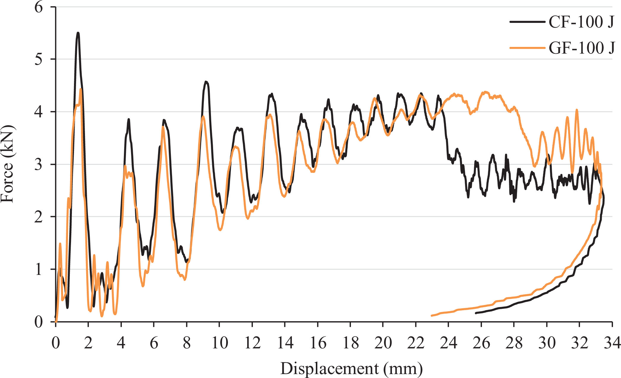
F-D curves for the reference CF and GF pipes under 100 J of impact energy.
The impact responses of hybrid pipe configurations H1, H2, and H3 are shown in Figure 7 corresponding to 50:50 composition of carbon/glass fibers. Similar trend was observed from these graphs in terms of large fluctuations with more severe damage occurring at increasing impact energy level. Important observation from the F-D curve was noticed during the increase of loading part up to a certain point of loading prior to a sudden degradation, especially with specimens H1 and H2. A remarkable disparity was recorded for these pipes in terms of peak load, and maximum displacement resulting in increase in energy absorption for the specimens H1 and H2. The increased energy is a result of further collapse and progressive failure in the fibers of pipes constituent materials.

F-D curves for the hybrid pipes of different stacking sequences at 50:50 fiber content ratio under 100 J energy.
The effect of fiber content ratio variation on the impact response is represented in Figure 8 for the hybrid pipe specimens H4, H5, and H6 corresponding to 75:25 of carbon–glass fiber ratio. Again, specimens having the stacking sequence of exterior glass fiber (H4) and carbon fiber (H5) on the impacted side suffered from abrupt drop at the end part of loading section on the graphs, confirming extreme damage occurrence. More specifically, specimen with glass fibers on exterior side H4 absorbed most of the energy with large displacement as a result of large delamination area, and fiber breakage occurring in the specimen (i.e. close to penetration case). While the alternative hybrid configuration H6 exhibited improvement in the impact resistance as a result of higher impact force with lower maximum deformation. Also, lower induced damage was observed on H6 sample due to good energy absorption capability among the other samples.

F-D curves for the hybrid pipes of different stacking sequences at 75:25 fiber content ratio under 100 J energy.
Energy absorption and damage effects
Absorbed energy by the impacted specimens during the impact test is an important parameter in the assessment of accumulative damage and toughness of the materials. 28 From the F-D graphs shown in this study, it is clear that all the impacted cases showed a rebounding trace which means that most part of the impacted energy was absorbed by the specimens and the balance was recovered by the impactor as a residual energy. The energy absorption by the specimens is expressed through the different failure modes observed on the impacted pipes. The energy absorption values for all the impacted pipe configurations are summarized in Tables 3 and 4 subjected to 50 J and 100 J, respectively. Generally, all the hybrid pipe configurations displayed better energy absorption compared to carbon specimens under 50 J impact energy. While for the impacted energy of 100 J, reference carbon and glass fibers specimens as well as H1 and H4 samples showed critical damage regions. Higher maximum displacement and further energy absorption observed on these samples were the indications behind this behavior.
Glass fibers absorbed energy better than carbon fibers under 50 J energy displaying a larger damaged area by the specimen while under 100 J of impact energy both samples suffered mainly from fiber breakage. Permanent damages of fibers have been noticed for both levels of impacted energies with more severe damage observed at 100 J of impact energy combined with other failure modes as shown in Figure 9(a) and (b).

Damage zones of composite pipe configurations: (a) pure samples at 50 J energy, (b) pure samples at 100 J energy, (c) hybrid pipes (H1–H3) at 50 J energy, (d) hybrid pipes (H1–H3) at 100 J energy, (e) hybrid pipes (H4–H6) at 50 J energy, and (f) hybrid pipes (H4–H6) at 100 J energy.
The failure modes of specimens with 50:50 ratio of carbon to glass fiber (i.e. H1, H2, and H3) subjected to 50 J of impact energy are shown in Figure 9(c). No significant improvement was recorded in terms of impact damage resistance as compared to the reference samples, but an improvement was observed in the energy absorption mechanism especially as compared with the carbon sample. It is believed that the addition of high elongation fiber (i.e. glass fiber) enhanced the energy absorption performance for the hybrid pipes as compared with the carbon samples. 29
Similarly, the macrograph images of impact response under 100 J of impact energy are shown in Figure 9(d) and somewhat different from 50 J of impact energy. Energy absorption capacity has decreased in the following sequence of H1, H2, and H3 specimens but the impact resistance has improved more for H3 followed by H2 and H1 samples, respectively. The increase in energy absorption noticed for specimens H1 and H2 was as a result of more fiber failure occurrence which is consistent with the sudden drop in F-D curves (Figure 7). Moreover, the pipe configurations H2 and H3 demonstrated improvement in impact damage resistance as compared with the reference cases under critical impact energy of 100 J (Figure 9(b) and (d)).
The visible damage zones for the specimens H4, H5, and H6 corresponding to fiber content ratio of 75:25 carbon–glass hybrid pipes are shown in Figure 9(e) and (f). These graphs for a similar stacking sequence but different impact energy of 50 J and 100 J, respectively. By one side, pipe samples of glass fiber on exterior side and alternative fiber configurations showed better impact resistance under 50 J of impact energy for both fiber content ratios. Besides it, the increase in carbon percentage on the 75:25 carbon-glass samples has caused to further damage especially for H4 and H6 samples under 50 J of impact energy as compared with similar stacking sequence of 50:50 carbon–glass samples.
Under 100 J impact energy, the specimens suffered from extreme damages with increasing in the impact damage resistance for configurations H6 followed by H5 and H4 based on the impact parameters described in Table 4, (see also Figure 9(f)). Specifically, samples of glass fiber at the impacted side (i.e. H1 and H4) exhibited good energy absorption performance due to the presence of glass fiber which has higher strain to failure ratio. While the alternative sequence samples (H3 and H6) showed better impact resistance regardless of fiber content ratio. Also, more induced damage was observed on the specimens with increasing carbon content up to 75% as a result of increased energy absorption by these specimens.
Micrograph inspection of failure modes
Different failure modes can be observed on the composite structures due to impact loading such as matrix cracking, delamination, fiber pullout, and fiber breakage or a combination of these modes. In order to detect the damage severity with a more detailed description among the impacted samples, the scanning electron microscope (SEM) technique was utilized. In this regard, SEM technique plays a significant role in assessing the damage and identifying the failure patterns. Because the damage becomes more severe with the impact energy of 100 J, the pipe specimens at this energy level have been adopted for evaluation. Micrographs of small sectioned samples at the surface of impact region were taken at the same magnification scale.
Figure 10(a) to (h) shows the SEM images for the specimens under 100 J of impact energy, which represents the most critical failure. Reference glass specimens showed extreme damages represented mainly by fiber breakage and deep matrix cracks (see Figure 10(a)). This behavior was supported with the lower peak force and maximum displacement observed on the impact curves. Similar trend was observed on the carbon samples with slightly less damage severity. Generally, an improvement of damage patterns was noticed for the hybrid specimens compared with reference samples. Specifically, for the fiber content ratio of 50:50 carbon–glass configurations, specimens of exterior glass (H1) showed more damage followed by exterior carbon samples (H2) and finally alternative sample (H3). Likewise, the samples of 75:25 carbon–glass content ratio with alternative pipe configuration (H6) experienced less damage severity while exterior glass samples (H4) suffered more damage. Accordingly, the excessive energy absorption which was determined through F-D curves for the specimens H1 and H4 explains the severe damages observed on the SEM photographs of these samples. In addition, more severe damages were observed on the specimens H4, H5, and H6 corresponding to 75:25 carbon–glass fiber content as compared to the samples H1, H2, and H3 corresponding to 50:50 carbon–glass fiber ratio. As mentioned before, the increased percentage of carbon fiber had led to the observation of severe damages.

Failure modes of carbon–glass pipe configurations close to the impacted surface under 100 J impact energy: (a) glass fiber specimen, (b) carbon fiber specimen, (c) hybrid pipe sample H1, (d) hybrid pipe sample H2, (e) hybrid pipe sample H3, (f) hybrid pipe sample H4, (g) hybrid pipe sample H5, and (h) hybrid pipe sample H6.
Conclusions
Hybrid composite pipes consisting of carbon/glass FRPs were tested experimentally under low-velocity impact for two levels of impact energy, 50 and 100 J. Different stacking sequences of the plies and fiber content ratios were utilized for this study. Impact characteristics and micrograph scanning technique of damage zones were adopted to compare the impact resistance and induced damage among the specimens. The following concluded points were extracted from the analysis: All the impact tests experienced a rebounding type impact for both of impact energies with significant fluctuations observed on F-D graphs as a result of high applied energies and the absence of internal pressure loading during the impact. For 50 J of impact energy, the hybrid configurations showed better energy absorption than reference carbon fibers specimen. Specifically, an improvement of the damage severity was observed on the specimens H1 and H3 as a result of lower values of energy absorption. The increased percentage of carbon fibers corresponding to 75:25 carbon–glass hybrid pipes led to further damage observed especially on H4 and H6 configurations under 50 J of impact energy. The impact parameters such as peak load, maximum displacement, contact time, and energy absorption tend to increase with the increase in impact energy level up to 100 J. Therefore, permanent damages were observed on the specimens with increasing impact energy. For the impact energy of 100 J, placement of glass fiber on the exterior layers (i.e. H1 and H4) showed higher maximum displacement confirming higher energy absorption for both fiber composition ratios. While the alternative pipe samples of varying stacking sequence (H3 and H6) were observed to have better impact damage resistance, with a better response of damage formation as a result of recorded energy absorption values. For both the fiber content ratios (i.e. 50:50 and 75:25) of carbon/glass specimens subjected to 100 J impact energy, the energy absorption capacity has been decreased in sequence of H1, H2, and H3 specimens. Meanwhile, the severity of damage was improved more for H3 followed by H2 and H1 samples. Similar scenario occurred for H4, H5, and H6 configurations in terms of energy absorption and damage severity.
Finally, due to the increasing use of filament wound structures, which are subjected to different damage patterns due to impact loading, further studies should be conducted focusing on the prediction of maximum impact force under high impact energies. As such, it would be possible to adequately describe the maximum peak force that is an important parameter for the impact damage resistance investigation. It gives an indication on the material failure as the material sustains a major damage or complete failure at this load level.
Footnotes
Declaration of conflicting interests
The author(s) declared no potential conflicts of interest with respect to the research, authorship, and/or publication of this article.
Funding
The author(s) received no financial support for the research, authorship, and/or publication of this article.