
Abstract
The aim of this study was to produce carbon nanotubes (CNTs)/polymer composite fibers by wet spinning without any solvent. The functionalized multiwalled-carbon nanotubes (F-MWNTs)/epoxy resin was synthesized by in situ polymerization method. Epoxy resin, F-MWNTs, and curing agent were mixed and injected by a syringe pump. The effects of operating parameters including the percentage of CNTs and the extrusion velocity of the syringe pump on the dispersion and alignment of F-MWNTs in the cross-section of F-MWNTs/polymer composite fibers were investigated. The composite fibers were characterized by tensile strength analysis, scanning electron microscopy (SEM), and electrical conductivity analysis. The experimental results showed that a decrease (30 ml/h to 15 ml/h) in extrusion velocity increased the electrical conductivity of composite fibers by more than 3%. This behavior was attributed to the higher alignment of F-MWNTs and improved conducting pathways along the composite fiber axis, as observed by SEM. In addition, by reducing extrusion velocity (30 ml/h to 15 ml/h), the tensile strength of composite fibers was enhanced just over twofold due to the better arrangement of CNTs which can be attributed to the further retention time of composite fibers and the pressure of the walled-needle. Moreover, the higher the processing time of spinning, the lower electrical conductivity of the fibers is which might be due to the higher coagulation of fibers.
Introduction
Nowadays, carbon nanotubes (CNTs) are widely known for their excellent properties such as high tensile strength, thermal resistance, electrical conductivity, and low density. 1,2 These properties make CNTs ideal candidates as reinforcement elements in CNT/polymer composite. 3 -7 One possibility of using CNT-polymer can be CNT fibers, 8 -11 which have been applied in a variety of applications such as wind turbine blades, transistors, sports goods, and aerospace. 12 -14
For these applications, CNT fibers can be produced by different approaches like electrophoretic and dielectrophoretic spinning, solid-phase spinning, and solution spinning. 15,16 Among these approaches, solution spinning is used commercially due to its ease and low-cost processing. 17 However, in this approach, CNTs poorly disperse and tend to aggregate in the solution because of their Van der Waals interactions. 16
Typically, superacids have been used to promote the dispersion process. 18 -21 Nevertheless, these days applying superacids is not prevalent due to some drawbacks such as harmfulness and in some cases it is only limited to the single-walled CNTs. 22 In addition, superacids are removed from coagulated fibers and create voids in them, which reduce the mechanical properties of fibers significantly. 23,24
Different types of polymers like polyvinyl alcohol and polyacrylonitrile, 10,25 -27 and surfactants, 28,29 were used as an appropriate alternative for superacids in order to improve mechanical properties. As regards, CNTs were poorly dispersed in the polymer matrix. 30 -32 In this approach, CNT fibers transfer to a polymer solution to cover these fibers with a layer of polymer which leads to a further tenacity. 25,33 However, there are many voids in the texture of fibers which has a negative effect on mechanical properties.
Consequently, at the beginning of the processing of the initial CNT/polymer composite, polymers are used in order to reduce voids which in addition to filling voids can lead to a stronger CNT/polymer bond. 34,35 Despite the use of polymer improves the mechanical properties of composite fibers, poor dispersion of CNTs in the polymer is one of the serious problems yet. For this purpose, applying a solvent in the initial polymer/solvent solution is a proper strategy in order to improve dispersion. 10 Thus, the early addition of solvent in the mixture results in appropriate dispersion of CNTs in the solution. This CNT/polymer/solvent composite inject into a coagulation bath for removing solvent from coagulated fibers. But still removing the solvent is a disadvantage of this method which may reduce mechanical properties. 36
In this study, CNT/polymer composite fibers were produced by wet spinning without the coagulation bath, and the synthesis of functionalized multiwalled-carbon nanotubes (F-MWNTs), which can improve dispersion 37,38 and also mechanical properties, and epoxy resin followed by in situ polymerization approach.
Experimental
Materials
Commercial epoxy resin Ep 8035 DGEBA (bisphenol A epoxy) and 1150 curing agent (Epilox®—Hardener M 1150 is a modified polyamine adduct hardener for epoxy resins) were purchased from the Khatam-Stone Company, Iran. F-MWNTs (diameter of 20–30 nm, a length of 10–30 µm, purity > 95%, and degree of functionalization about 5 wt%) were purchased from the Carbon Structure Nano-Technology Company, Iran.
Preparation of CNTs/polymer composite
In order to produce a composite, 6 g epoxy resin and CNTs (0.5 wt%) were stirred for 5 min and then sonicated for 100 min. Thereafter, the curing agent was added in a stoichiometric ratio immediately to the CNTs/epoxy mixture stirring for 5 min. The final mixture was poured into a syringe.
Fiber spinning
For fiber spinning, the 20 ml glass syringe with 500 µm inner diameter needle was used. The fibers were simply extruded into a glass plate at various extrusion velocities (8, 15, 30, and 60 ml/h) and different times after adding curing agent, processing time (10, 20, 30, 40, and 50 min), by a syringe pump (Terumo, UK). Electrical conductivity was carried out to study the effect of these extrusion velocities on the produced fibers. An electrical circuit was applied to determine electrical conductivity. The tensile strength of the fibers with a diameter of approximately 1 mm was measured using an STM-150 tensile tester machine with pneumatic wedge grips (Santam Engineering Design Co., Iran). Scanning electron microscopy (SEM; VP 1450, LEO, Germany) images were also used to observe the CNTs arrangements along the fiber axis.
Results and discussion
Selection of appropriate CNTs percentage
Figure 1 depicts the electrical conductivity of fibers obtained at the constant extrusion velocity (30ml/h) and 10 min after adding the curing agent versus the concentration of CNTs. The excellent electrical conductivity of CNTs causes the improvement of this property in the fibers. So, when the percentage of CNTs increases, the electrical conductivity of fibers enhances as expected. On the other hand, by increasing CNTs, their distance from each other is decreased and consequently, the conducting pathways are increased. Therefore, at the fixed time (10 min) after adding the curing agent, the fiber containing 2 wt% CNTs reaches the highest electrical conductivity at 1.328 S cm−1.

The electrical conductivity of F-MWNTs/epoxy resin composite fibers versus the percentage of CNTs.
Figure 2 illustrates the tensile strength of fibers produced at the constant extrusion velocity (30 ml/h) and 10 min after adding the curing agent versus the percentage of CNTs. As it can be observed, the fiber containing 0.5 wt% CNTs has the highest tensile strength among the other fibers. Although the samples of 1 and 2 wt% containing further CNTs compared to the 0.5 wt% one, the tensile strength of them is lower than it.

The tensile strength of F-MWNTs/epoxy resin composite fibers versus the percentage of CNTs.
Since an overabundance of CNTs prevents excellent dispersion in CNTs/polymer mixture and maintains the proportion of CNTs agglomerated, sonication is not adequate to form the uniform mixture. Injection of this mixture by syringe can lead to the blocking of the narrow needle. Even if a needle with a larger cross-section is used, there are some zones, where CNTs do not disperse appropriately. This produced fiber can be easily fractured because of low mechanical properties. Thus, the major contribution to the enhancement of the tensile strength of fiber containing 0.5 wt% CNTs can be attributed to the improvement in dispersion 31,32 of the CNTs in a polymer matrix, which, in turn, boosts the alignment of them in the needle.
Eventually, whereas by an increasing percentage of CNTs, the electrical conductivity of fibers enhances, the tensile strength declines. Therefore, the composite fibers containing 0.5 wt% CNTs are selected as an appropriate percentage of CNTs due to the modified mechanical and electrical properties and also the ease processing. In the following, this selected percentage of CNTs is applied in order to investigate the effects of the extrusion velocity on the electrical conductivity and tensile strength.
Electrical conductivity
Figure 3 demonstrates the electrical conductivity of composite fibers at different extrusion velocities (8, 15, 30, and 60 ml/h) versus the processing time (10, 20, 30, 40, and 50 min). As it can be observed, at all times, the electrical conductivity of fiber rises with decreasing extrusion velocity. As shown in Figure 3, the electrical conductivity differences between the produced fibers at 15 and 30 ml/h, especially at 10 min, are quite sensible. When the CNTs/polymer composite is inserted through the needle by the pressure of the syringe pump, a significant reduction of cross-section causes CNTs align along the fiber axis. To align CNTs through the needle, the adequate retention time is essential for maintaining in aligning position after extrusion. Otherwise, the CNTs return to the dispersed position before coming into the needle. Therefore, by decreasing the extrusion velocity, there is an adequate retention time for aggregation and alignment of CNTs along the fiber axis due to the pressure of the walled-needle.
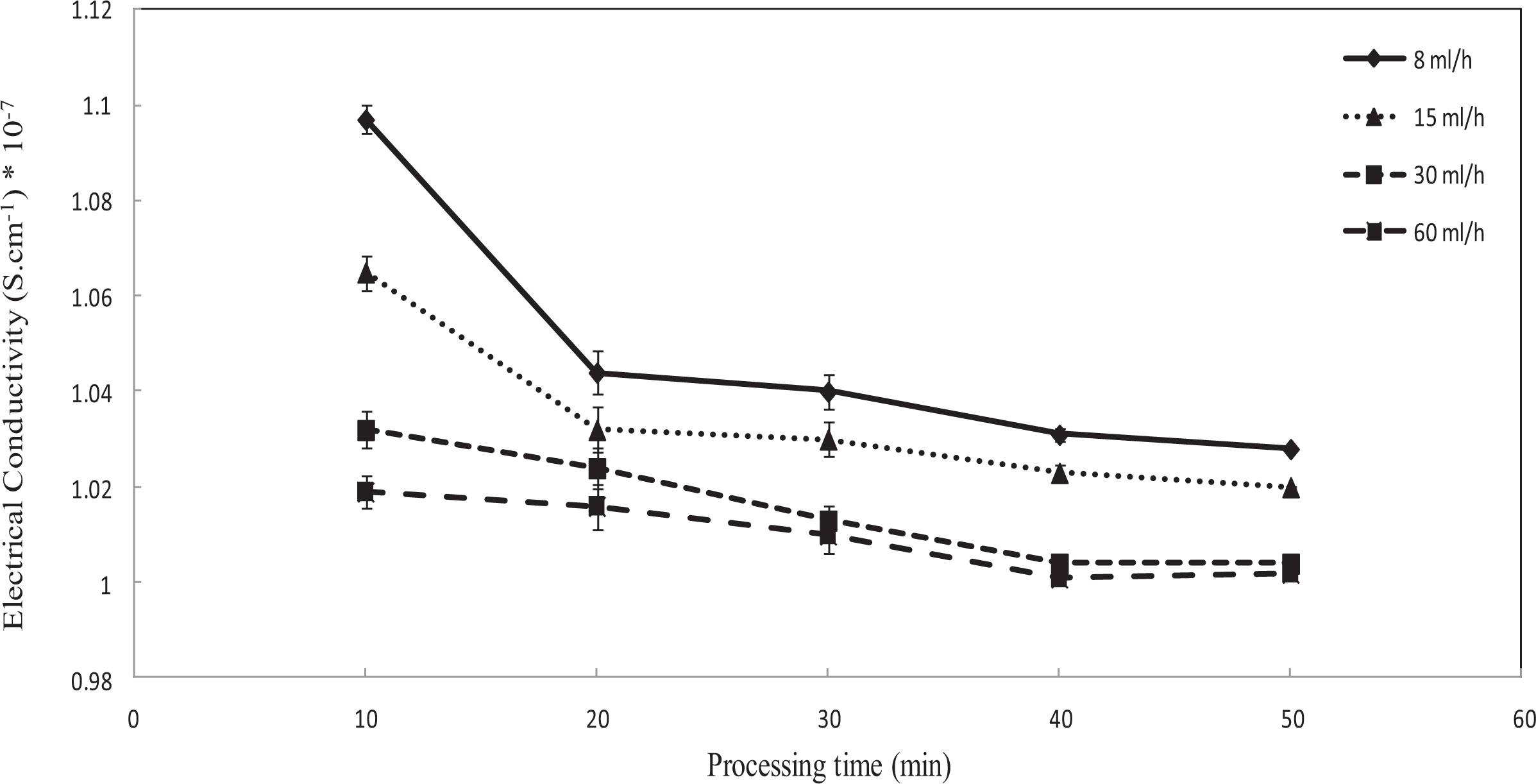
The electrical conductivity of F-MWNTs/epoxy resin composite fibers in different extrusion velocities versus time after adding the curing agent.
As it can be observed, by increasing the processing time up to 40 min, the electrical conductivity of fibers fall, which precedes a leveling off by 50 min. By the passage of time after sonication and extrusion, CNTs tend to return to the initial status due to the Van der Waals interactions. By adding the curing agent into the CNTs/polymer composite, after a while, the fibers are coagulated and formed. During the processing time, both coagulation and aggregation of CNTs may cause the segregation of them from the fiber axis. Thus, the segregation of CNTs from the fiber axis and aggregation in a section of fiber can cause the reduction of conducting pathways and also the electrical conductivity by 40 min.
As it can be seen, at the end of the process between 40 min and 50 min, nearly all the curves tend to a similar electrical conductivity trend. The aggregation of CNTs is continuing so that fiber roughly takes its final form and there are no sensible changes in the electrical conductivity of the fibers. Therefore, a period of no change between 40 min and 50 min in the electrical conductivity can be attributed to the final formation of fibers.
Tensile strength
Figure 4 illustrates the tensile strength of composite fibers (produced 10 min after adding the curing agent and 0.5 wt% CNTs) based on the extrusion velocity changes. As it can be observed, by declining the extrusion velocity, the tensile strength of fibers significantly increases from 0.12 GPa in 60 ml/h to 1.03 GPa in 8 ml/h due to better arrangement of CNTs. As mentioned above, by reducing the extrusion velocity, aggregation and alignment of CNTs along the fiber axis increase. As noticed in electrical analysis, the tensile strength differences between the produced fibers at 15 and 30 ml/h are also marked. In fact, aggregation and alignment of CNTs along the fiber axis are one of the factors which can improve the mechanical properties of the composite fibers. Therefore, the obtained results from the mechanical analysis are in agreement with the electrical analytic ones. It can be also said that the cited claims and reasons about the alignment of CNTs along the fiber axis at the low extrusion velocities and also segregation of them from the fiber axis at the high extrusion velocities are verified appropriately.

The tensile strength of F-MWNTs/epoxy resin composite fibers versus the extrusion velocity of the syringe pump.
SEM analysis
Figure 5 schematically presents two different angles of the cross-section of fibers. Based on the figures, when a fiber is pulled and broken down if the arrangement of CNTs is aligned along the fiber axis, CNTs are visible circular in cross-sectional images (Figure 5(a)), and if the arrangement of CNTs is angled along the fiber axis, the interval surface of CNTs can be seen in the cross-sectional images (Figure 5(b)).

The proposed schematic representation for the two different angles of the cross-section of F-MWNTs/epoxy resin composite fibers. (a) Central point, (b) Side point.
Figure 6 displays SEM images of the central point of the cross-section of composite fibers with various extrusion velocities. As it can be observed, white dots indicate the cross-section of CNTs, which have appeared from the pulling of fibers. While Figure 6(a) and (b) shows an approximately homogeneous aggregation and alignment of CNTs along the fiber axis, at the higher velocities (Figure 6(c) and (d)), a considerable decline in aggregation and alignment of CNTs along the fiber axis is visible. In fact, if there are sufficient retention time and pressure (the low extrusion velocities), the aggregation and the alignment of CNTs would happen close to the fiber axis. Therefore, SEM images further confirm the obtained results of electrical and mechanical analysis, which by decreasing extrusion velocity, electrical conductivity and tensile strength are improved.

SEM images obtained from the central point of the cross-section of F-MWNTs/epoxy resin composite fibers produced by (a) 8 ml/h, (b) 15 ml/h, (c) 30 ml/h, and (d) 60 ml/h.
Figure 7 reveals SEM images of the side point of the cross-section of composite fiber with different extrusion velocities. As it can be observed, when the extrusion velocity increases, the heterogeneous aggregation of CNTs away from the fiber axis is most perceptible (Figure 7(d)). As mentioned in electrical and mechanical analysis, the electrical conductivity and tensile strength difference between two produced fibers in 15 and 30 ml/h are considerable (Figure 7(b) and (c)). In Figure 7(a) to (d), white dots and lines indicate the cross-section and the interval surface of CNTs, respectively, which have emerged from the pulling of fibers. Based on Figure 7, it can be said that when applied pressure of the walled-needle quickly relieves (the higher extrusion velocities), the aggregation of CNTs would be away from the fiber axis. Therefore, the heterogeneous aggregation of CNTs away from the fiber axis causes the decrease of conducting pathways, electrical conductivity, and tensile strength as well.

SEM images obtained from the side point of the cross-section of F-MWNTs/epoxy resin composite fibers produced by (a) 8 ml/h, (b) 15 ml/h, (c) 30 ml/h, and (d) 60 ml/h.
Table 1 illustrates the amounts of electrical conductivity, tensile strength, and enhancement percentages of the fibers manufactured 10 min after adding the curing agent and 0.5 wt% CNTs in various extrusion velocities. As the extrusion velocity reduces from 60 ml/h to 8 ml/h, the electrical conductivity gradually rises to about 8% and also tensile strength picks up almost 760% significantly. These results detected that the increased contact between the CNTs supplied by the higher alignment not only increased their strength but also created additional pathways along the fiber axis for electrical conduction.
Electrical conductivity, tensile strength, and enhancement percentages of the fibers at various extrusion velocities.
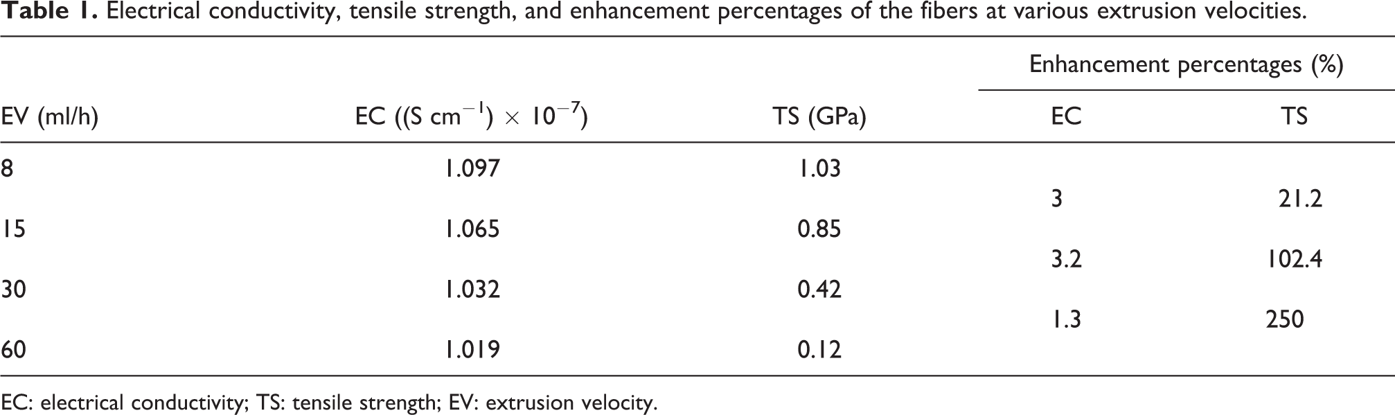
EC: electrical conductivity; TS: tensile strength; EV: extrusion velocity.
Conclusions
In this work, the F-MWNTs/epoxy resin composite fibers were produced by a non-solvent in situ polymerization approach, and the effects of extrusion velocity on the electrical and mechanical properties of F-MWNTs/epoxy resin composite fibers are investigated. The results are expressed that by reducing the extrusion velocity from 60 ml/h to 8 ml/h, the electrical conductivity of composite fibers enhances almost 8% (at 10 min) due to the higher alignment of CNTs and the improved conducting pathways along the fiber axis. In addition, when the processing time increases, the electrical conductivity of composite fibers declines, which might be due to the higher coagulation of fibers.
Moreover, the tensile strength of composite fibers noticeably was increased roughly eightfold by decreasing the extrusion velocity because of the better arrangement of CNTs which can be ascribed to the further retention time and the pressure of the walled-needle, as revealed by SEM images.
Footnotes
Acknowledgement
The authors are grateful to the Iran Nanotechnology Initiative Council.
Declaration of conflicting interests
The author(s) declared no potential conflicts of interest with respect to the research, authorship, and/or publication of this article.
Funding
The author(s) received no financial support for the research, authorship, and/or publication of this article.