
Abstract
Polymer composite samples were prepared consisting of NC-826 epoxy and approximately 0.1–0.5 wt% aerographite nanomaterial. The compression properties of the various samples were evaluated at strain rates of 10−3–10−1 s−1 using a universal testing machine. The fracture surfaces of the tested samples were examined by scanning electron microscope. Additional composite samples consisting of NC-826 epoxy and 0.3 wt% multiwalled carbon nanotubes (MWCNTs) were prepared and tested under the same compression strain rates of approximately 10−1–10−3 s−1. In general, the results showed that the addition of aerographite nanomaterials to the resin matrix is beneficial in suppressing crack propagation under compression loads and therefore leads to an improved stress, toughness, and fracture strain compared to the pure resin sample. The results additionally showed that the use of MWCNTs as a reinforcement material yields a further small improvement in the mechanical properties of the sample.
Introduction
Composite materials can be broadly defined as any material made of two or more materials with different characteristics, which when mixed together, produce a new material with a higher strength than that of any of the constituent materials. Generally speaking, composite materials are formed by combining a substrate with a suitable reinforcing material. The substrate often has the form of a polymer resin, such as epoxy, phenol, polyethylene, or polyamide, 1 -6 while the reinforcing material may be carbon fiber, fiberglass, boron fiber, or Kevlar fiber. The bonding surface between the substrate and the reinforcing material is called the interface and the interface is the main basis of the bonding strength between the two materials, and hence has a critical effect on the overall mechanical properties of the composite material.
Fiber type composite materials have many favorable properties, including high strength, low weight, good wear resistance, excellent fatigue strength, and good resistance to corrosive wear. As a result, they are widely used in many industries nowadays, including the electromechanical industry, car and motorcycle industry, shipbuilding industry, aerospace industry, sports industry, and so on. 7 -9 However, for applications in which additional strengthening, or some other special property, is required, nanomaterials, such as aerographite, silicon dioxide, carbon nanotubes (CNTs), titanium dioxide, and layered double hydroxide, may also be added to the composite material to change its interface characteristics and enhance its mechanical behavior. 10 -19 Aerographite nanomaterial is a lightweight synthetic cellular material with a 3D interconnected network of tubular carbon. 20 -22 Furthermore, they have unique microstructures consisting of carbon nanoparticles and nanopores and this study uses it as a reinforcement on the epoxy matrix to investigate the effect on mechanical property. In the present study, polymer composite samples are prepared by adding approximately 0.1–0.5 wt% of aerographite nanomaterials to NC-826 epoxy. The compression properties of the composite samples are evaluated at strain rates ranging from 10−1 s−1 to 10−3 s−1 using a universal testing machine and are then compared with those of a composite material consisting of the same epoxy resin but 0.3 wt% of multiwalled carbon nanotubes (MWCNTs). In general, the results show that both nanomaterials yield an effective improvement in the compression properties of the composite material compared to the original resin sample.
Experimental procedure
Aerographite nanomaterials (0.1, 0.3, and 0.5 wt%) were added to glass beakers containing 10 g of butanone. The mixture was stirred ultrasonically for 10 min to ensure a uniform dispersion of the aerographite and was then poured into preformulated NC-826 epoxy resin. The aerographite was mixed into the resin using a three-roller dispersion system and the resin was then placed in a vacuum oven and heated at a temperature of 60°C to extract the residual air. After approximately 6 min, clear bubble bursts were observed. Hence, the vacuum pump was shut off and the resin was kept in the vacuum oven to continue to extract the air. Once all of the air bubbles had been removed, the resin was taken out of the oven and a plastic injection needle was used to suck up some of the resin and inject it into a preheated mold. The process was performed slowly and carefully to avoid the injection of air bubbles into the mold. The mold was placed in an oven and heated at a temperature of 60°C for 10 min. After the baking process, the mold was allowed to cool naturally to room temperature and the test piece was removed and cut into test specimens with a length and diameter of 7 mm using a low-speed diamond cutter.
Compression tests were performed under room temperature conditions at strain rates of approximately 10−1–10−3 s−1 using a low-speed universal testing machine (Struers Minton, Cleveland, USA). The stress–strain data collected for each sample were used to evaluate various properties of interest, including Young’s modulus, the yield stress, the toughness, and the fracture strain. Scanning electron microscopy (SEM) observations were additionally performed to examine the fracture surface features of each sample.
Results and discussion
Stress–strain response of aerographite/epoxy samples
Figures 1 to 3 show the stress–strain curves of the various aerographite/epoxy samples tested at strain rates of 10−1, 10−2, and 10−3 s−1, respectively. As shown, the stress–strain curves of the samples are generally insensitive to the level of aerographite addition at each of the considered strain rates, particularly at lower values of the strain. However, at higher values of the strain and lower values of the strain rate, a noticeable difference in the stress–strain response of the various samples becomes apparent. As the test power exceeds the yield point, differences in aerographite material characteristic performance caused by nano-granule size effect can be determined through observation of the test pieces’ macrodamage pattern. Figures 4 and 5 show the fracture histories of the pure epoxy sample and an aerographite/epoxy sample with 0.5 wt% nanomaterial addition under a strain rate of 10−1 s−1. It is seen that the pure epoxy sample undergoes instantaneous rupture at a strain of 0.5. By contrast, the aerographite/epoxy sample undergoes a gradual process of crack initiation and propagation before final rupture occurs.

Static stress–strain curves of aerographite/epoxy samples with different aerographite additions at strain rate of 10−1.
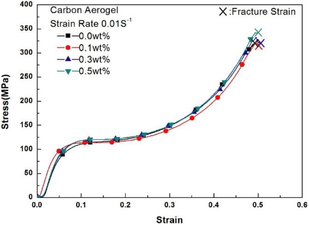
Static stress–strain curves of aerographite/epoxy samples with different aerographite additions at strain rate of 10−2.
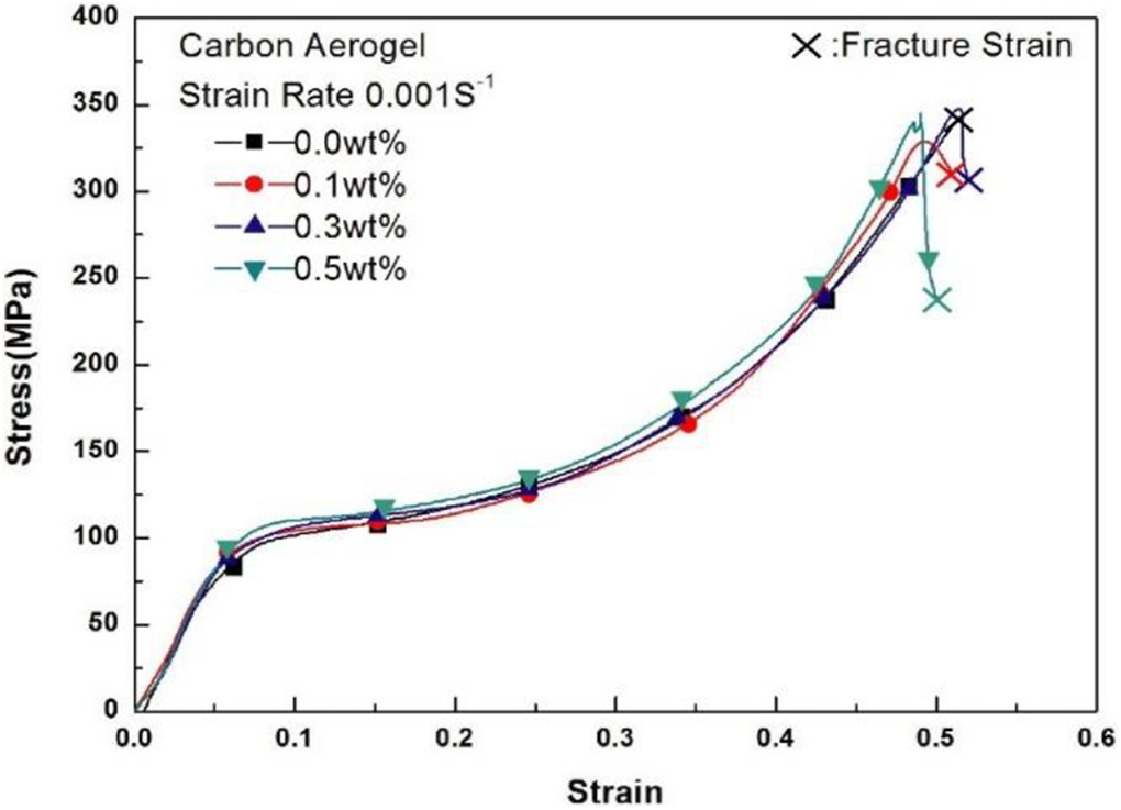
Static stress–strain curves of aerographite/epoxy samples with different aerographite additions at strain rate of 10−3.

Fracture features of epoxy sample and aerographite/epoxy sample deformed under strain rate of 10−1 s−1.

Schematic illustrations and photographs of fractured epoxy sample and aerographite/epoxy sample deformed under strain rate of 10−1 s−1. (Note that the composite sample contains 0.5 wt% areographite.)
Young’s modulus of aerographite/epoxy samples
Table 1 and Figure 6 show Young’s modulus values of the various samples, as obtained from the linear portions of the stress–strain curves shown in Figures 1 to 3. For each sample, Young’s modulus reduces slightly with an increasing strain rate. For the highest strain rate of 0.1 s−1, there is no significant difference in Young’s modulus values of the samples with different levels of aerographite addition. However, for lower strain rates of 0.01 and 0.001 s−1, Young’s modulus increases slightly as the aerographite addition increases from 0 wt% to 0.3 wt% and then falls slightly as the aerographite addition is further increased to 0.5 wt%.
Young’s modulus values (GPa) of epoxy samples and aerographite/epoxy samples deformed under different strain rates.


Variation of Young’s modulus with strain rate for pure epoxy samples and aerographite/epoxy samples.
Yield stress of aerographite/epoxy samples
Table 2 and Figure 7 show the yield stress values of the various samples, as measured directly from the stress–strain curves shown in Figures 1 to 3. As the material experiences different strain load from the static compression test, the yield point of the test materials increased as their aerographite content increased (Table 2 and Figure 7). When the content reached 0.5 wt%, the maximum load force must be used to induce plastic deformation in the material. Thus, we theorize that the component with 0.5 wt% aerographite content has the highest yield point. It can be seen that for each sample, the yield stress increases with an increasing strain rate. Furthermore, for a given strain rate, the yield stress increases with an increasing aerographite addition. Finally, the sensitivity of the yield stress to the level of aerographite addition increases as the strain rate increases. It is noted that the present results for the yield stress are consistent with those reported by Shadlou et al. 23 for graphene reinforced/epoxy nanocomposite material.
Yield point values (MPa) of epoxy samples and aerographite/epoxy samples deformed under different strain rates.


Variation of yield stress with strain rate for pure epoxy samples and aerographite/epoxy samples.
Toughness and fracture strain of aerographite/epoxy samples
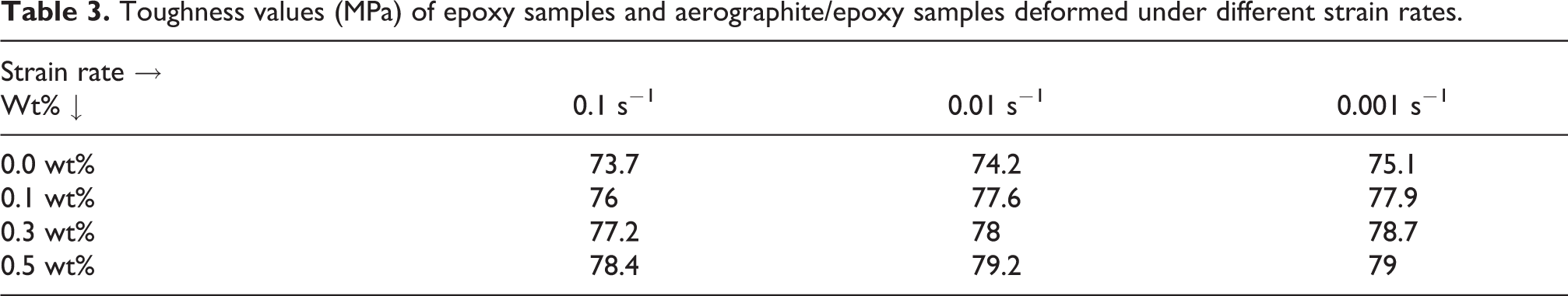
Table 3 and Figure 8 show the toughness properties of the various samples, as evaluated by the area under the stress–strain curves shown in Figures 1 to 3. For each sample, the toughness reduces slightly with an increasing strain rate. 24 However, for a given strain rate, the toughness increases with an increasing aerographite addition. In other words, the sample with 0.5 wt% aerographite addition is able to absorb a greater amount of strain energy prior to fracture. However, as given in Table 4 and Figure 9, the fracture strain increases only very slightly with an increasing aerographite addition, even at the highest strain rate of 0.1 s−1.
Toughness values (MPa) of epoxy samples and aerographite/epoxy samples deformed under different strain rates.
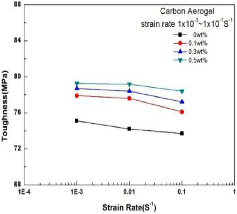
Variation of toughness with strain rate for pure epoxy samples and aerographite/epoxy samples.
Fracture strains of epoxy samples and aerographite/epoxy samples deformed under different strain rates.


Variation of fracture strain with strain rate for pure epoxy samples and aerographite/epoxy samples.
SEM analysis of aerographite/epoxy rupture surfaces
Figure 10(a) to (c) presents SEM images of the fracture surfaces of the aerographite/epoxy samples containing 0.1, 0.3, and 0.5 wt% aerographite, respectively. (Note that the strain rate is 10−1 s−1 in every case.) In general, the results show that all three samples have a fine dispersion of aerographite particles. Moreover, holes are observed in the matrix as a result of reinforcement for the composite materials. These holes provide space for the substrate to undergo plastic deformation and improve the ability of the composite material to absorb structural damage as a result. Figure 10(d) and (e) shows the fracture surface of 0.5 wt% aerographite composite materials. The images show that the aerographite particles block the crack propagation path and hence suppress further cracking. In other words, the particles yield an effective improvement in the overall strength of the composite material.
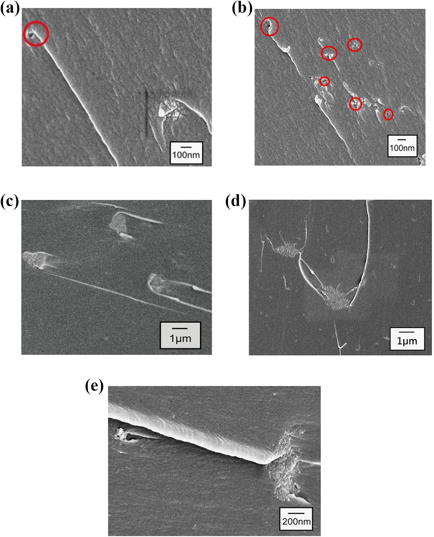
SEM images of fracture surface features of composite aerographite/epoxy samples with aerographite additions of (a) 0.1 wt%, (b) 0.3 wt%, and (c) 0.5 wt%. Close-up views of interaction effect between aerographite material and cracks in (d) 0.3 wt% and (e) 0.5 wt%.
Comparison of MWCNTs and aerographite reinforcement materials
Overall, the results presented above suggest that the addition of aerographite to the epoxy resin is beneficial in improving its mechanical properties. Moreover, an aerographite addition of 0.5 wt% results in the highest yield stress, toughness, and fracture strain. For comparison purposes, additional composite samples were fabricated consisting of the same epoxy resin (NC-826) but MWCNTs as the reinforcement material. In accordance with the findings of Kinloch et al., 24 the level of MWCNT addition was set as 0.3 wt%. The MWCNT/epoxy samples were compression tested under the same strain rates as those used for the aerographite/epoxy samples (i.e. approximately 10−1–10−3 s−1) Tables 5 and 6 compare the experimental results obtained for the yield stress and fracture strain, respectively, of the two samples under each of the considered strain rates. Overall, the results show that the addition of MWCNTs results in a small improvement in both material properties for all values of the strain rate. In other words, the addition of an appropriate quantity (3 wt%) of MWCNTs is also beneficial in improving the strength and energy absorption performance of the composite epoxy samples due to that the MWCNTs were effectively dispersed into the epoxy matrix than aerographite.
Yield point (MPa) comparison of composite epoxy samples with MWCNT and aerographite reinforcement materials.

Fracture strain comparison of composite epoxy samples with MWCNT and aerographite reinforcement materials.

Conclusion
This study has examined the compression performance of composite epoxy samples consisting of NC-826 resin and 0.1, 0.3, and 0.5 wt% aerographite nanomaterials under strain rates of approximately 10−1–10−3 s−1. The results obtained for the aerographite/epoxy samples with 0.5 wt% nanomaterial addition have been compared with those obtained under the same strain rate conditions for composite samples consisting of NC-826 resin and 0.3 wt% MWCNTs. The experimental results support the following main conclusions. The addition of aerographite to the resin matrix results in a small improvement in Young’s modulus, particularly at lower values of the strain rate. In addition, the yield stress, fracture strain, and toughness improve with an increasing level of aerographite addition. The SEM observation results suggest that the performance improvement can be attributed to the effects of the aerographite particles in suppressing crack propagation within the deformed sample matrix. Because of the total volume effect, comparison of the total energy absorbed by different carbon material shows that the lower the strain rate the less obvious the effects of different carbon material and different weight percentage. However, as the strain rate becomes higher, the performance difference of different carbon materials and weight percentages also becomes increasingly greater. The improvement in the yield stress, fracture strain, and toughness with an increasing aerographite addition is more pronounced under higher strain rates due to the lower volume effect. The addition of 0.3 wt% MWCNTs to the epoxy resin results in a small improvement in the yield point and fracture strain properties of the composite epoxy sample compared to those obtained using 0.5 wt% aerographite. Aerographite nanomaterial and MWCNTs are both beneficial in improving the mechanical properties of epoxy-based composite materials. Moreover, the performance improvement is generally more pronounced under higher strain rates and higher levels of nanomaterial addition. However, given an excessive amount of nanocarbon materials, clustering of the nanomaterials within the resin matrix occurs, which results in the formation of holes from which cracks may subsequently propagate under compression loading. Thus, for practical applications, the quantity of reinforcement addition must be carefully controlled.
Footnotes
Declaration of conflicting interests
The author(s) declared no potential conflicts of interest with respect to the research, authorship, and/or publication of this article.
Funding
The author(s) disclosed receipt of the following financial support for the research, authorship, and/or publication of this article: This research was funded by the Ministry of Science and Technology, Taipei, ROC, under Grant No. 106-2628-E-992 -302 -MY3 and 107-2221-E-992-060.