
Abstract
Smart materials find vital applications in the aerospace industry due to their ability to adapt to surrounding conditions according to design requirements and applicability. Piezoelectric materials are commonly used under the category of smart materials for transducer applications. Among piezoelectric materials, piezo polymer polyvinylidene fluoride (PVDF) is widely used for structural health monitoring (SHM) applications of composite structures, acoustic emission (AE) sensor, accelerometer, strain gauge, pressure sensor, and so on because of its outstanding piezo stress constant (g 33), piezo strain constant (d 33), flexibility, and lightweight. In this article, glass fiber-reinforced polymer (GFRP) laminates have been prepared by embedding the PVDF sensor into GFRP for the first time. A detailed study has been done on the behavior and characterization of the PVDF sensor embedded in GFRP. The PVDF sensors embedded in laminates were subjected to impact test, where a constant weight of 5.5 kg was dropped from a height of 10–60 mm in the interval of 10 mm, and the voltage response of the PVDF sensor was recorded. Sensitivity analysis and AE test of the PVDF sensor in GFRP were also carried out. This is useful for various aerospace applications especially for SHM of aircraft.
Introduction
Composites find a wide range of applications in the aerospace domain as an emerging research area because of their outstanding strength to weight ratio. 1 Composite structures, however, are very sensitive to flaws and voids, which results in early damage of the structure such as delamination, fiber breakage, and so on. 2 Microfracture failure may be noticed in the composites before the final failure of the structure due to stress concentration and non-homogeneity of composites. 3 Thus the detection and identification of the internal defects in a composite structure are of prime focus. The nondestructive testing (NDT) for health monitoring of these composite structures is very important to prevent early failure and damages. Acoustic emission (AE) monitoring is a promising NDT technique used for the identification of different types of failure in composites. 4 It is more convenient than other NDT techniques because it can detect the dynamic processes associated with the degradation of structural integrity. It is nondirectional and can be used in situ to monitor a structure while it remains in service. The conventional systems used for structural health monitoring (SHM) are deprived of a reliable energy source. The electronic devices required to maintain such a diagnostic system would have to rely on a limited energy supply (batteries) and would either have a very low power consumption or, ideally, be capable of generating the required energy from the available immediate environments. 5 The selection and integration of diagnostic and actuation devices within structural composites depend on the material such as piezoceramic, piezopolymer, fiber optics, memory alloys, and strain sensor. 6 Polyvinylidene fluoride (PVDF) is an electro-active fluoro-polymer exhibiting a wide variety of mechanical and electric properties, namely, piezoelectricity, pyroelectricity, nonlinear optical property, and so on. 7 These properties make PVDF highly adaptable for applications in a wide range of industries such as spanning aerospace, automotive, civil engineering, biomedical, and health care. They are extensively used in SHM systems, vibration and noise control, distance ranging and navigation, and security systems. 8 Bare PVDF films have been indigenously developed in the laboratory since the last decade and have been tested for various applications. 9 The behavior and properties of the PVDF sensor embedded in a composite structure is the area of interest as the emerging research area for SHM applications. This research work has been specifically focused on understanding the impact damage response. In the past, impact damage response on natural fiber composites relating to properties of fibers, matrices, fiber–matrix interfaces, and fiber geometry and architecture has been studied by various authors. 10 –12 Recent studies have been carried to evaluate the low-velocity impact response of polymeric composite materials which combine experimental tests to numerical simulations. Fragassa et al. 13 provided guidelines to model a basalt fiber-reinforced laminate when subjected to falling weight impact tests. They reported that low-velocity impact tests on polymer composites can be replicated numerically with a simplified digital geometry.
Bunea et al. 14 studied low-velocity impact behavior of fabric-reinforced hybrid composites with a stratified filled epoxy matrix at 90.629 J impact energy. They analyzed the influence of stratified epoxy matrix properties modified with different fillers and fibers oriented at different angles on impact response.
Low-velocity impact response was also investigated by Liu et al. 15 for hybrid epoxy laminates reinforced with carbon unidirectional fibers and five harness satin woven carbon fiber fabric at impact energy levels of 10, 17, and 25 J. The presence of 90° layers in composite structures led to reduced response time and growth of delamination along the transverse direction.
Barouni and Hom 16 investigated impact studies for low-velocity–induced damage of flax, glass, and glass flax hybridized composite laminates at 25 and 50 J incident energy levels, both experimentally and numerically. They found that damage is more at lower energy levels.
In this study, laminate was prepared by embedding the PVDF sensors in the glass fiber-reinforced polymer (GFRP) composite structure for the first time, and sensitivity analysis in the composite structure was carried out for the PVDF sensor. The developed laminates were also subjected to AE and impact tests and the results are discussed in detail.
Experimental details
PVDF granules were procured from M/s Solvay (Mumbai, India). PVDF films were made using these granules by the hot press technique method. The films thus obtained were in alpha phase which is the most stable phase of PVDF. To achieve the beta phase, which is required for sensor applications, the films were stretched thermomechanically. After the mechanical stretching process, the confirmation of beta phase has been done using the X-ray diffraction technique. In the beta phase, the domains in the structure are not oriented. So, corona poling was carried out by applying a high electric field to align the domains in the direction of electric field to achieve the piezoelectric properties of PVDF. The whole process has been described elsewhere. 17 –20 After the preparation of PVDF films, piezo test is carried out using the piezometer system to find out the piezoelectric charge constant (d 33) and its capacitance value for different samples.
Then the laminates were prepared using bidirectional glass fibers as a reinforcing material, epoxy 5052 resin as a matrix material, and LY 5052 as a hardener. The glass fiber was tailor-made at National Aerospace Laboratories, Center for Societal Missions and Special Technologies, Bangalore division. The process of preparation of laminates has been described in the ‘Results and discussion’ section.
Properties of glass fiber are tabulated in Table 1 and the properties of the PVDF sensor (active area 15 × 15 mm2) are given in Table 2.
Properties of glass fiber.

Properties of PVDF sensor.

PVDF: polyvinylidene fluoride.
For the laminates embedded with PVDF sensor, the sensitivity analysis has been carried out using the Teledyne LeCroy (Bangalore, India) wave surfer 3054 oscilloscope which has a bandwidth of 500 MHz, 4 channel O-SCOPE, 4 GS/s sampling rate, and 10 MPT memory size.
The resulting laminates were checked for impact using the low-velocity impact machine (Natioanal Aerospace Laboratories, Advanced Composite Division, Bangalore) with a standard mass of 5.5 kg and the maximum energy measured up to 100 J and the data were recorded in the data acquisition system NIDAQ6521 (National Instruments, Bangalore, India).
Finally, the laminates were checked for the AE test using MISTRAS-2001 (Mistras Group Inc, Mumbai, India) (massively instrumented sensor technology for received acoustic signals). It is a parallel processing architecture that has 2–256 channels. Here, the sampling per channel is 10 MHz (20 MHz optional). It has 16-bit Analog to Digital converter with low noise.
Results and discussion
The composite laminate of glass/epoxy was prepared using the hand layup technique 18 as shown in Figure 1. The lamination process was carried out using layers of glass fiber. Each layer was cut in the length of measurement 130 mm and a width of 50 mm. The hand layup fabrication technique was carried out where glass fiber and resin (hardener and epoxy) were taken in the ratio of 60/40. 21, 22

Hand layup method.
Initially, the mold was prepared by applying the releasing agent to its surfaces. The first layer of glass fiber was laid on the surface of the mold and resin was applied on the laid fiber.
After applying the resin, the second layer of glass fiber was laid and the process was repeated until the required thickness of the laminate was achieved. The PVDF sensor (Table 3) was prepared and embedded inside the laminate during the layup process. Once the layup process is done, the laminate was allowed to cure for 24 h at room temperature. Figure 2 shows the bare PVDF sensor, and Figure 3(a), (b), (c), and (d) shows the PVDF sensor embedded in laminates with 3, 5, 8, and 22 layers of glass fibers, respectively.
Specifications of the PVDF sensor.

PVDF: polyvinylidene fluoride.
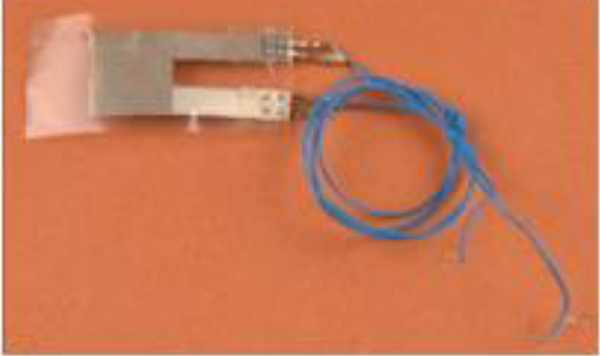
Bare PVDF sensor. PVDF: polyvinylidene fluoride.
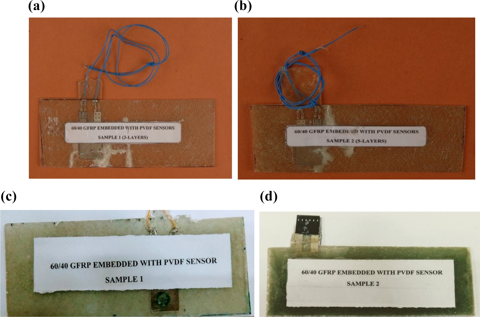
The composite of 60/40 ratio GFRP embedded with PVDF sensor of sample 3, 5, 8, and 22 layers: (a) sample 1—3-layered GFRP; (b) sample 2—5-layered GFRP; (c) sample 3—8-layered GFRP; and (d) sample 4—22-layered GFRP.
The specifications of PVDF sensors having a length of 37 mm, width 20 mm, and thickness 0.077 mm are embedded in the laminates, the piezo strain constant, and capacitance of different PVDF samples have been tabulated in Table 3. The specifications of composites embedded with PVDF sensor are listed in Table 4.
Specifications of composites embedded with PVDF sensor.

PVDF: polyvinylidene fluoride.
Since the purpose of developing this laminate was for SHM, the laminate of PVDF sensor composite was subjected to sensitivity test, impact test, and AE test to know the response of the sensor. The parameters like voltage, energy, and response of the sensor were noted. These results of the laminated PVDF sensor and PVDF bare sensor were compared.
Sensitivity analysis
The composite structures embedded with PVDF sensor were subjected to sensitivity analysis. Initially, the sensitivity of the sensor in laminates was checked with the application of the lead break test and the output response was recorded using a digital storage oscilloscope. The comparative analysis is done for laminated GFRP with a PVDF sensor and a bare PVDF sensor. The following test carried out is tabulated in Table 5.
Sensitivity analysis of laminates embedded with PVDF sensor and bare PVDF sensor.

PVDF: polyvinylidene fluoride; RMS: root mean square.
From Table 5, it is noted that the PVDF sensor embedded in laminate is sensitive to lead break test like bare PVDF sensor and the output voltage varies with the number of GFRP layers. The bare PVDF sensor peak to peak voltage is 4.07 V and root mean square (RMS) is 133 mV. For the laminated PVDF sensor with the number of glass fiber layers from 3 to 22 (Table 5), the peak to peak voltage varies in the range of 3.23–7.67 V and RMS voltage varies in the range of 108–200 mV. So as the number of GFRP layers increases, the output voltage from PVDF sensors also increases.
Impact test
The composite laminates embedded with PVDF sensor after checking the sensitivity were subjected to drop weight (impact test) to analyze the impact behavior of the sensor for different layers of laminates and for which the voltage response was recorded. The aim of the experiment was to characterize the voltage response of the sensor in a composite structure for a known mechanical mass (impact) of 5.5 kg with different energy.
Energy has been calculated using the following equation:

where m is the mechanical mass (5.5 kg), g is the gravitational force, and h is the height from which the weight has been dropped.
The test was carried out by mounting the sample in the impact machine as shown in Figure 4(a) to (c). The weight of 5.5 kg was dropped on the specimen. The voltage response of the embedded PVDF sensor was recorded, and the graph has been plotted.
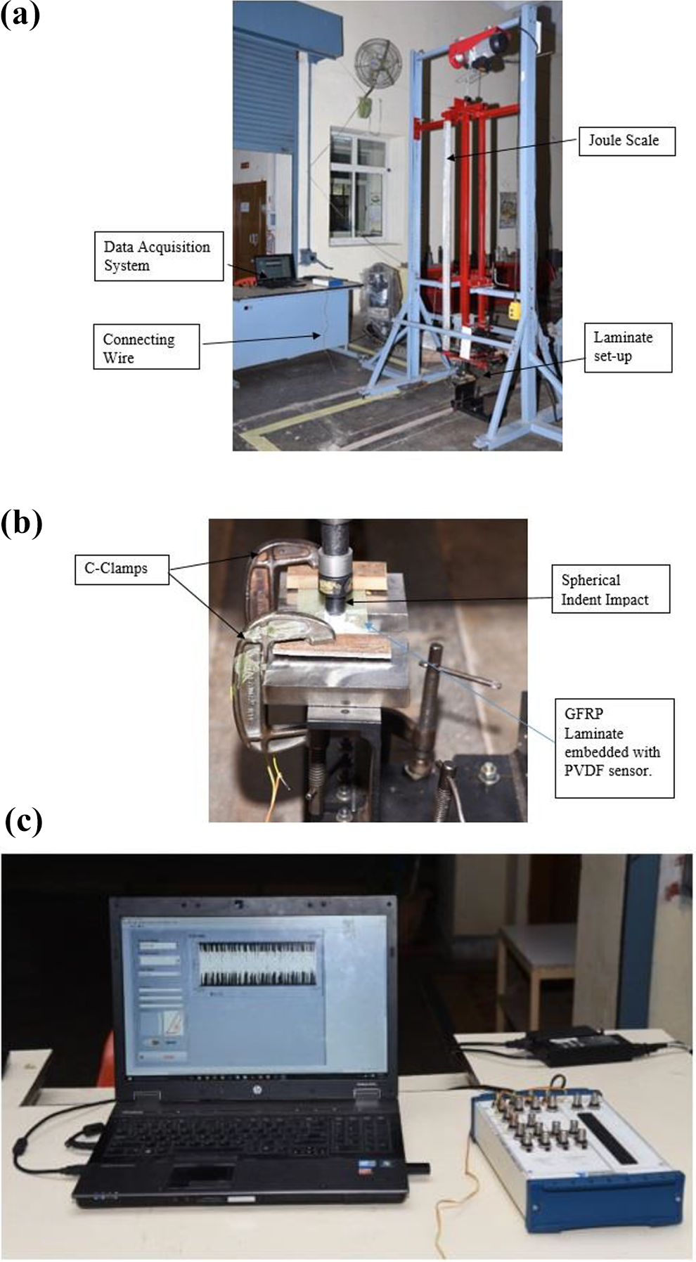
(a) Low-velocity impact machine. (b) Arrangement of GFRP laminates for the impact test. (c) NIDAQ6521 data acquisition system to record the response of PVDF sensor.
Initially, the impact test was carried out with a constant weight of 5.5 kg and a height of 10 mm, and the experiment was repeated up to a drop height of 60 mm with the step of 10 mm height, the output response of each impact was recorded in data acquisition system NIDAQ6521.
Figure 5 shows the comparison of voltage obtained from all four laminates with 3, 5, 8, and 22 glass fiber layers embedded with PVDF sensor. From Figure 5, it can be inferred that as the drop height is increased by keeping the mechanical mass constant for a value of 5.5 kg, the applied energy also increases relatively, which results in the increase of output voltage of the PVDF sensor in the composite. The voltage of sample 1 (three layers) suddenly comes down at 50 mm height because the thin laminate thickness (1 mm), could not withstand the impact of 2 J and fractured. The voltage noted down at that particular point of failure of the laminate was 9.64 V. Further, the test was carried out by changing the position of the laminate and the test was conducted at 2.5 J at a height of 50 mm where the obtained voltage was less (4.26 V). Even though laminate was fractured, the sensor responded well. The voltage response of sample 2 (five layers) from the height of 50 mm was recorded to be 9.12 V after which the laminate fractured. Since the remaining laminates with 8 and 22 layers were thick, they could bear the impact of mechanical weight from the height 60 mm, the voltage obtained was 9.86 V for 8 layers and 10.36 V for 22 layers from the height of 60 mm.
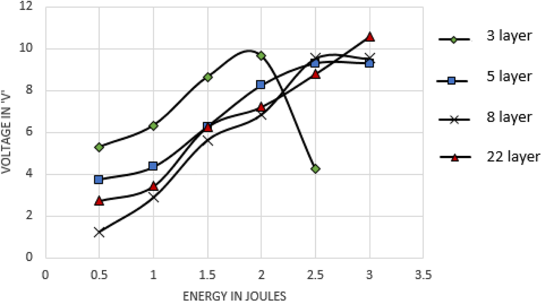
Voltage response of PVDF sensors embedded in 3, 5, 8, and 22 layers.
It must be noted that even though some laminates were fractured during tests due to the repeated impact on the same point, the PVDF sensors still responded very well. It is concluded that even if the laminate fractured, the PVDF sensor was safe and its sensitivity was still retained inside the laminate. This property makes PVDF sensors very useful for aerospace SHM applications.
AE test
AE monitoring is a promising NDT technique used for the identification of different types of failure in composites. The GFRP laminates embedded with PVDF sensor were subjected to an auto-sensor test (AST) for sensor response. The aim of this experiment was to analyze the behavior of the PVDF sensor in the composite structure when subjected to AE. MISTRAS-2001 AE system was used to carry out the AE test in which the GFRP laminates with PVDF sensor were connected to the AE system through a pre-amplifier, as shown in Figure 6. AST was performed to check the response of the sensors by giving an excitation of 20 pulses for 5 ms. The output response of the sensors due to excitation was recorded and tabulated (Table 6)

AE test setup.
AE characterization for PVDF sensors embedded in GFRP laminates.

AE: acoustic emission; PVDF: polyvinylidene fluoride; GFRP: glass fiber-reinforced polymer.
Table 6 also compares the AE test results of the PVDF sensor embedded in the composite structure with the AE test results of the bare PVDF sensor.
The response of the sensors was simulated through pulse using (AST) AE system. A simulated pulse was applied on the sensor and the response was picked by the MISTRA-2001 system. The AE test results of different layers 3, 5, 8, and 22 were compared with the AE test results of the bare PVDF sensor. From the AE test results, it can be noted that the amplitude and duration are almost the same in all the samples. The energy reduces as the number of GFRP layers increases. No change in amplitude of PVDF sensor after embedding in the composite structure and bare PVDF sensor highlights the versatility of PVDF sensor. The response of PVDF sensors in GFRP laminates is given in Table 6.
The PVDF sensors used were bare and un-damped, their duration is large due to continuous ringing, and the energy under this envelope is relatively high. Hence, the corresponding ring down counts is also high due to the persistent crossing of the threshold (45 dB) by the signals. 12
The consistency in the results of sensitivity, impact, and acoustic properties of PVDF indicates that they are good for the SHM application.
Conclusion
The PVDF sensor in GFRP laminates of different layers (3, 5, 8, and 22 layers) was prepared using a hand layup technique for the first time. The response of PVDF sensor embedded in GFRP was compared with the bare PVDF sensors. The sensors in GFRP laminates were subjected to sensitivity test using lead break test and were found to be as sensitive as bare PVDF sensors. This indicates that PVDF sensors have retained their sensitivity even after embedding in the composites. It was found that as the number of layers in the laminate increase, the output voltage increases. The impact test was then conducted on laminates where they were subjected to a known mechanical mass (impact) of 5.5 kg with different energy by varying the drop height from 10 mm to 60 mm and the output response was recorded. It was found that as the drop height of mechanical mass on the laminates increases, energy increases and the voltage also increases. Also, PVDF sensitivity retained even after laminate fractured due to the impact till the PVDF sensor is not damaged.
The GFRP laminates with PVDF sensor were subjected to AST for sensor response to identify different types of failures in composites. It was found that the amplitude and duration were almost the same in all the samples. The acoustic energy value decreases with an increase in the number of GFRP layers.
All these results make PVDF sensors very useful for SHM applications in the aerospace industry.
Footnotes
Acknowledgements
The authors thank the Director and Head of Material Science Division, NAL for their kind support. The help of Mohan Kumar for providing materials and that of P Pitchai and Sanjeev Kumar for carrying out the impact and AE tests are highly appreciated. The authors also thank CSIR and AR&DB for funding the project.
Declaration of conflicting interests
The author(s) declared no potential conflicts of interest with respect to the research, authorship, and/or publication of this article.
Funding
The author(s) disclosed receipt of the following financial support for the research, authorship, and/or publication of this article: This work was supported by CSIR and AR&DB.