
Abstract
Autoclave-cured carbon fiber-reinforced plastics (CFRPs) are widely used in aerospace and aviation industries. However, they have a limited field in automotive or marine industries in which both the unit costs of the products and applicability to mass production are of primary concern. Therefore, out-of-autoclave (OoA) processed products having similar mechanical properties with autoclave cured ones have been extensively studied. In this study, infrared (IR) curing, an OoA curing method, was investigated. The aim of the study is to propose a reliable temperature control method for an IR CFRP curing oven. A methodology that provides the surface and through-thickness temperature distribution of IR cured epoxy matrix CFRP was introduced. Optimum ply number and the distance between the heat source and the material were determined. Material surface was separated into nine virtual regions and region-based thermal evaluations were made by means of the thermal camera images and thermocouple data. Temperature distribution through thickness was determined. When designing a robust IR thermoset CFRP curing process, one should consider the temperature distribution on the surface and through the thickness of the material.
Introduction
Fiber-reinforced plastics are widely used in various industries, such as aeronautics and aviation, automotive, marine, leisure, and sports. The main advantage of composite materials is their high specific strength (S/W). Hence, these materials, specifically carbon fiber prepreg materials, are mostly used in advanced applications like race car manufacturing or aeronautics. The manufacturing processes of composite materials are based on the curing of the resin system, which includes fiber reinforcements. The most advanced curing process of composites is autoclave curing. Autoclave is an oven in which predetermined temperature and pressure cycles are applied. The most advantageous aspect of autoclaves is that the highest fiber-volume fractions are achievable. 1 This serves the superior mechanical properties to autoclave cured parts. However, due to high capital and operating costs of autoclave manufacturing, developing out-of-autoclave (OoA) methods is of great academic and industrial interest. 2 Many researchers have been held aiming to reduce the unit production costs of composite parts. These efforts are generally focused on either developing vacuum bag only prepregs, which do not need autoclave pressure or processing systems utilizing different curing mechanisms. 3
Curing mechanisms can be divided into two main categories: radiation and thermal curing mechanisms. Electron beam curing 4,5 and ultraviolet curing 6 are typical OoA radiation curing methods based on ionization of polymers. Thermal OoA curing methods are microwave, 7,8 ultrasonic, 9 laser, 10 induction, 11 resistance, 12 and infrared (IR) 13 curing techniques. Although microwave and IR curing mechanisms are based on electromagnetic radiation, since their frequencies are low for ionization, they are considered as thermal processes. 14 The aforementioned alternative methods are generally found unstable and hard to adjust the process parameters, resulting in nonhomogeneous temperature distribution. 14 Therefore, the efforts regarding these methods are to overcome these limitations basically. Process parameters of curing methods are of great importance in the mechanical performance of the product. Thus, the significant parameters should be determined and optimized considering both the production costs and the performance of the product.
IR is an emerged curing method for composites due to its high energy efficiency, predictable heating rate (the temperature change in unit time), and volumetric heating mechanism. However, it is frequently used for heating of thermoplastic materials, which necessitate fast heating instead of a long-term complex curing states including different heating rates and dwell temperatures. Limited studies about thermoset IR curing have been accumulated in the literature. Schmidt et al. 15 investigated the surface temperature distribution of thermoplastic sheets numerically. They found out that halogen lamps were the most efficient heat source. Kumar et al. 16 studied the IR postcuring of handlaid glass fiber-reinforced polymer composite laminates and concluded that IR needs just 25% of curing time compared to conventional thermal curing.
In this study, the process parameters of IR curing of a carbon fiber-reinforced plastic (CFRP) thermoset prepreg regarding the temperature distribution were investigated. The temperature gradient through the thickness of the plate and the surface temperature distribution was examined. The optimum distance between the heat source and the material and the through-thickness temperature gradient were determined experimentally.
Material and methods
Kordsa (Kordsa Composite Technologies Centre of Excellence, Istanbul, Turkey) brand twill weaved OM11 resin type CFRP prepregs were used in curing processes. The tensile strength, flexural strength, and fiber content (by weight) of the material are 733 MPa, 809 MPa, and 58%, respectively. 17 The manufacturer recommended cure cycle for this material is shown in Figure 1.

Cure cycle of the material.
Prepregs were cut at 100 mm × 260 mm dimensions and stacked to construct the samples. All samples were separated into nine equal parts. This implies that the samples were not physically separated, but they were considered as nine equal parts for more accurate temperature distribution conclusions (Figure 2(a)). One-, two-, three-, and four-layered laminates were used.

(a) Sample with nine equal parts and (b) thermocouple placement.
Thermocouples (TCs) were placed, as shown in Figure 2(b).
Test set up
In this study, CFRP materials were cured in a newly developed PLC controlled IR curing unit (Figure 3(a)). A short wavelength (1–3 µm) halogen IR lamp was used as a heat source. Copper end K type TCs and FLIR E6 thermal camera were used for temperature measurements. Lamp has 225-mm heating length and an aluminum reflector for focusing the light (Figure 3(b)). The PLC system was designed so as to simulate the given temperature cycles of the curing processes (see Figure 1). The curing unit utilizes a manual distance, adjuster, which allows adjusting the distance between the material and the heat source. The CFRP plies are laid on an 8-mm thick tempered glass on top of the oven, where the IR heater was put under at adjusted distance. The layer which is in contact with the tempered glass is considered as the bottommost layer. Experiments were conducted under a vacuum bag.

(a) IR curing unit and (b) halogen infrared lamp with distance adjuster.
Experiments
Experiments were performed in two stages. In the first stage, the optimum heat source-material distance was determined. For this purpose, temperature profiles on the surface of one layer of samples at 10, 15, 20, and 25 cm distances were determined. Thermal images were taken at every 10 s along with the tests by a FLIR E6 thermal camera (Kartal Otomasyon, Kocaeli, Turkey). Then, the images were processed and the average temperatures of all nine areas were obtained. In the second stage, at the determined optimum distance, four different layered samples were tested. The temperature profiles along the thickness were evaluated. Six hundred seconds were determined to be sufficient for both concluding the maximum temperatures at the predetermined distances and gaining an overall insight about the temperature change along the surface and thickness.
Results
The first stage of the experiments consists of the determination of an optimum heat source-material distance. In Figure 4, the heating rate can be considered as stable for 20 and 25 cm distances while it is clearly unstable in 10 and 15 cm distances. This shows that the control of the heating rate, which is crucial for the curing process, is difficult for 10 and 15 cm distances. This implies that for 10 and 15 cm distances, the temperature gradient along the material surface is difficult to control. The unstable fluctuations observed in 10 and 15 cm distances are believed to be a consequence of the extensive and unstable convective energy loss and radiant heat transfer occurring at the same time.
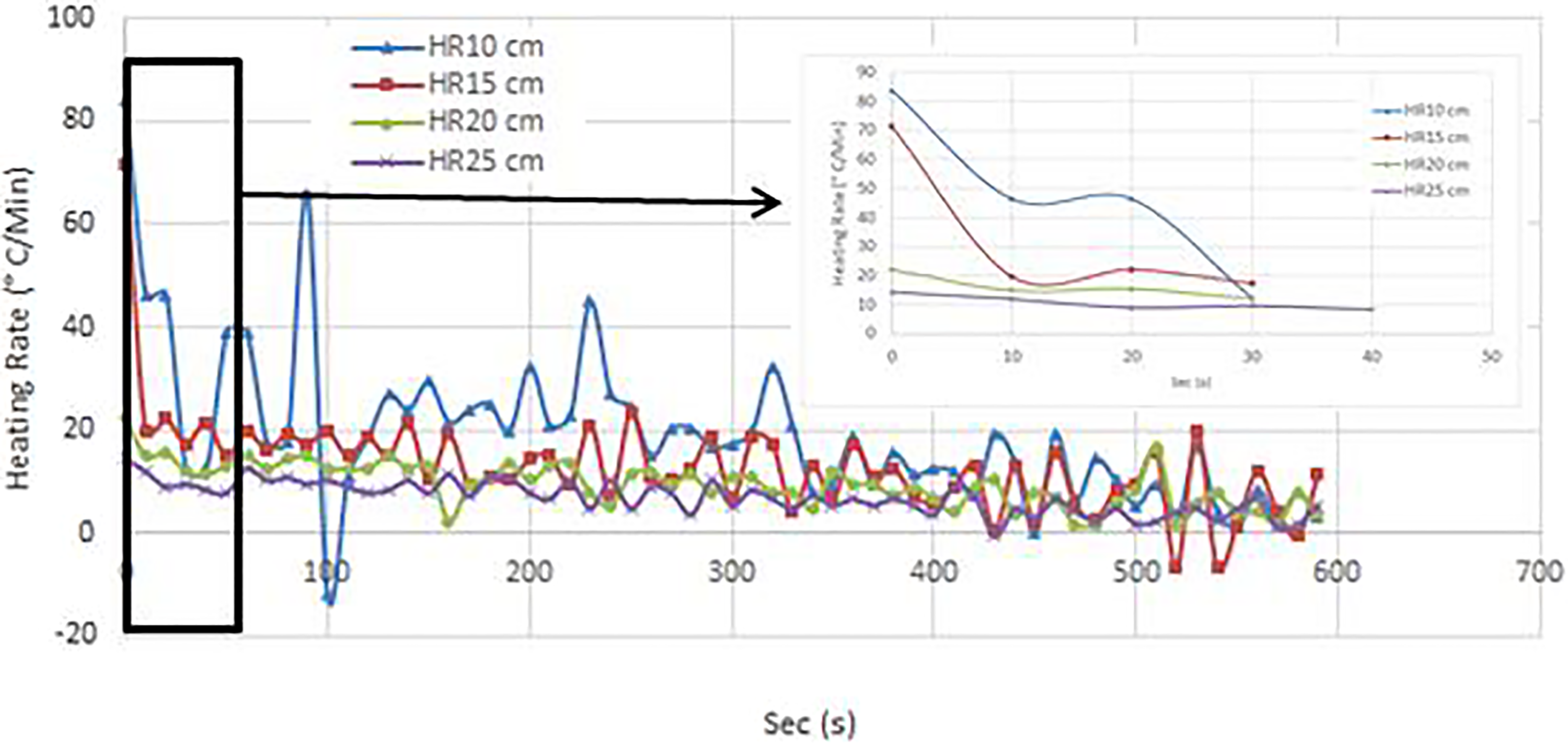
The heating rate measurements of the experiments conducted at different distances.
Figure 5 shows the temperature change during the heating process. It is seen that 20 cm distance is enough for reaching the maximum curing temperature (120°C). Therefore, considering the maximum available temperature and energy efficiency, 20 cm distance can be concluded to be the optimum heat source-material distance.
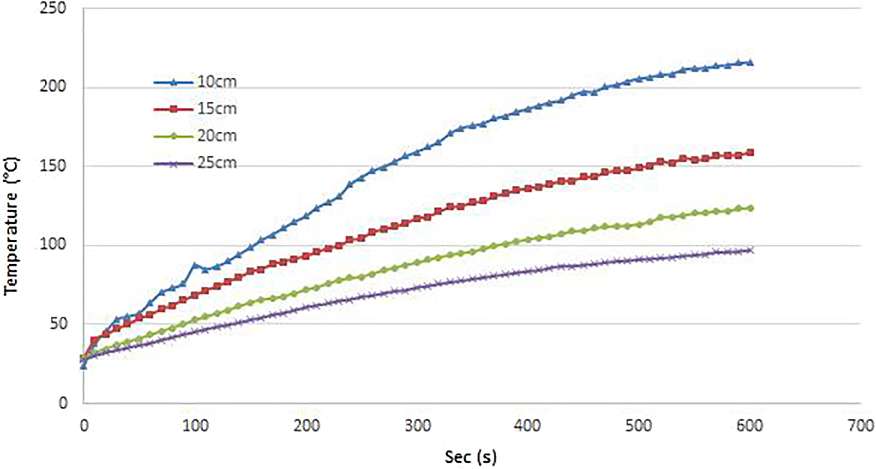
Temperature change on the material surface.
Temperature differences between the nine regions are shown in Figure 6. Temperatures were given as normalized temperatures of the regions (NT_Rn) for the sake of better distinguishing the temperature differences. “NT” states normalized temperatures while “R” states region, that is, R1 means region 1. Temperatures were normalized according to equation (1):

Normalized temperatures of the regions.

where
Table 1 presents the normalized temperatures of the regions and % differences. The latter implies the temperature gradient percentage of the normalized temperature of the related region with regard to the unity, that is, the normalized value of the
Normalized temperatures and % differences between regions.

Bold values state that the temperature differences of the first and fourth regions are below 3%. Therefore, these regions can be considered to be the best representative regions of the whole surface.
The second phase of the experiments was conducted to investigate the through-thickness temperature gradient. Experiments were applied at 20 cm heat source—sample distance. One-, two-, three-, and four-layered samples were tested. First, the representability of the first region was verified. The same normalization procedure at the first phase experiments was employed for all four layers. Thicknesses are proportionally increased with the number of layers. Figure 7 shows the change of normalized temperatures for all layers (NT_nL), through thickness, along with the experiment.

Normalized temperatures of four layers.
The difference between each layer is in good agreement with each other and also with the results of the previous test, as presented in Table 2. This justifies that the first region can be used as a pivot region for the TC feeding the PLC power unit to adjust the heating rates for the given cure cycle.
Normalized temperatures and % differences of different layers.

Figure 8 shows the real-time temperature differences for all layers. The real-time data were taken from four TCs that were put on between the layers coinciding with the first region. It seems likely that the bottommost layer was heated more than the others. It can be concluded that the bottommost layer was directly exposed to the IR waves.

Temperatures over time measured through the thickness.
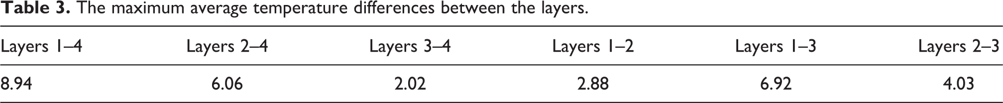
Table 3 presents the average temperature differences between each layer. It shows the maximum average temperature (MATD) between layers 1 and 4 as 8.94°C. The MATD between successive layers is in between the layers 2 and 3 with 4.03°C. This may be attributed to the shifting of heat transfer mechanism from the radiant heat transfer to conduction heat transfer after the second layer. Considering that the thickness of the four-layered sample is about 3 mm, the temperature gradient is approximately 3°C mm−1. This implies that one can assess the through-thickness temperature variation of the related product according to the thickness.
The maximum average temperature differences between the layers.
Conclusions
IR heating is known as an effective heating mechanism and has been used widely in thermoforming of thermoplastic composite materials as a rapid heating source. However, the process has not been deeply investigated in the curing of thermoset composites, specifically in slow cure cycles, which necessitate accurate heating rates and dwell temperatures. This study aims to determine the temperature distribution on the surface and gradient through the thickness of the sample while heating with an IR heater. Besides, the most effective material, heat source distance, was determined. Experiments were conducted in two phases. In the first phase, experiments showed that the optimum distance is determined to be 20 cm, considering the temperature homogeneity. In addition, the first region of the sample was found to be the most suitable representative region of the total surface with a below 3% temperature difference percentage.
In the second phase of the experiments, the temperature gradients through the thickness of the sample were investigated. The average temperature difference was found to be 3°C mm−1. These results may serve the researchers as design parameters, when constructing an IR curing oven, which is capable of homogeneously heating the carbon fiber-reinforced composite materials.
Footnotes
Declaration of conflicting interests
The author(s) declared no potential conflicts of interest with respect to the research, authorship, and/or publication of this article.
Funding
The author(s) disclosed receipt of the following financial support for the research, authorship, and/or publication of this article: This study was funded by Duzce University Coordination of Scientific Research Projects (DUBAP), Ref. 2017.06.05.603, for design and manufacturing of an infrared composite curing oven.